ARM System Memory Management Unit Architecture Specification
Document: IHI 0070H.a
Version: SMMUv3.0 / SMMUv3.1 / SMMUv3.2 / SMMUv3.3 / SMMUv3.4 / SMMUv3.5
Copyright: © 2016-2026 Arm Limited or its affiliates
This is a Markdown conversion of the ARM System Memory Management Unit (SMMU) Architecture Specification for online reading and search.
Chapters
| Chapter | Title | Description |
|---|---|---|
| 1 | About this specification | References, terms, scope |
| 2 | Introduction | History, feature versions (v3.0–v3.5), system placement |
| 3 | Operation | Software interface, streams, data structures, translation, queues, caches, security |
| 4 | Commands | Command queue commands (CFGI, TLBI, CMD_SYNC, etc.) |
| 5 | Data structure formats | STE, CD, L1STD, L1CD, event records |
| 6 | Memory map and registers | Full register definitions (SMMU_IDR*, SMMU_CR*, etc.) |
| 7 | Faults, errors and Event queue | Fault model, event record formats, error handling |
| 8 | Page request queue | PRI page request interface |
| 9 | Address Translation Operations | ATOS (Address Translation Operations) |
| 10 | Performance Monitors Extension | PMU counters, events, registers |
| 11 | Debug/Trace | Debug features |
| 12 | RAS | Reliability, Availability and Serviceability |
| 13 | Attribute Transformation | Memory attribute transformation rules |
| 14 | External interfaces | AXI/ACE/CHI interface requirements |
| 15 | Translation procedure | Detailed translation algorithm |
| 16 | System and Implementation Considerations | Integration guidance |
| 17 | MPAM | Memory System Resource Partitioning and Monitoring |
| 18 | MEC | Support for Memory Encryption Contexts |
Source
About this specification
Chapter 1 About this specification
1.1 References
This specification refers to the following documents:
-
[1] PCI Express[®] Base Specification Revision 6.0 . PCI-SIG.
-
[2] Arm[®] Architecture Reference Manual for A-profile architecture . (ARM DDI 0487) Arm Ltd.
-
[3] Arm[®] Architecture Reference Manual Supplement, Memory System Resource Partitioning and Monitoring (MPAM), for A-profile architecture . (ARM DDI 0598) Arm Ltd.
-
[4] Arm[®] System Memory Management Unit, SMMU architecture version 2.0 . (ARM IHI 0062) Arm Ltd.
-
[5] TDISP eXtended TEE (XT) Extensions . PCI-SIG.
-
[6] Compute Express Link Specification . (Revision 1.1) CXL Contractual SIG.
-
[7] Arm[®] Generic Interrupt Controller, GIC architecture version 3.0 and version 4.0 . (ARM IHI 0069) Arm Ltd.
-
[8] AMBA[®] AXI and ACE Protocol Specification . (ARM IHI 0022) Arm Ltd.
-
[9] IO Remapping Table Platform Design Document . (ARM DEN 0049) Arm Ltd.
-
[10] Arm[®] CoreSight ™Architecture Specification 3.0 . (ARM IHI 0029) Arm Ltd.
-
[11] Arm[®] Reliability, Availability, and Serviceability (RAS) System Architecture . (ARM IHI 0100) Arm Ltd.
-
[12] Arm[®] Base System Architecture 1.1 . ARM DEN 0094D.
-
[13] Arm[®] Server Base System Architecture . (ARM DEN 0029) Arm Ltd.
1.2 Terms and abbreviations
This specification uses the following terms and abbreviations.
ASID
Address Space ID, distinguishing TLB entries for separate address spaces. For example, address spaces of PE processes are distinguished by ASID.
ATOS
SMMU facility providing VA-to-IPA/PA translations using system-accessible registers. In addition, VATOS provides a second set of registers for direct use from a virtual machine, with the added constraint that only VA-to-IPA translations can be returned.
ATS
PCI Express [1] term for Address Translation Services provided for remote endpoint TLBs
ATS Translated transaction
A memory transaction input to the SMMU, in which the supplied address has been translated. In PCIe this is indicated with the AT TLP field value 0b10. For more information see 3.9 Support for PCI Express, PASIDs, PRI, and ATS .
Bypass
A configuration that passes through a stage of translation without any addresses transformation is using bypass. If an SMMU does not implement a translation stage, that stage is considered equivalent to a bypass configuration.
CD
Context Descriptor.
Client device
A device whose incoming traffic to the system is controlled by an SMMU.
Completer
An agent in a computing system that responds to and completes a memory transaction that was initiated by a Requester.
CONSTRAINED UNPREDICTABLE
Where an instruction can result in UNPREDICTABLE behavior, the architecture specifies a narrow range of permitted behaviors. This range is the range of CONSTRAINED UNPREDICTABLE behavior. All implementations that are compliant with the architecture must follow the CONSTRAINED UNPREDICTABLE behavior. In body text, the term CONSTRAINED UNPREDICTABLE is shown in SMALL CAPITALS.
DVM
Distributed Virtual Memory, a protocol for interconnect messages to provide broadcast TLB maintenance operations (among other things).
E2H
EL2 Host Mode. The Virtualization Host Extensions in Armv8.1 [2] extend the EL2 translation regime providing ASID-tagged translations. In this specification, EL2-E2H mode is the abbreviation that is used.
EI
Embedded Implementation. For more information see 3.16 Embedded Implementations .
Endpoint (EP)
A PCI Express [1] function, used in the context of a device that is a client of the SMMU.
GPC
Granule Protection Check
GPC fault A Granule Protection Check fault, arising either because a Granule Protection Table lookup could not be completed, or because the lookup was successful and the access being checked failed the check.
GPF
Granule Protection Fault. The fault reported when a Granule Protection Table lookup is successful, but the access being checked fails the Granule Protection Check.
GPT
Granule Protection Table. An in-memory structure that describes the association of a Location and a PA space.
HTTU
Hardware Translation Table Update. The act of updating the Access flag or dirty state of a page in a given descriptor which is automatically done in hardware, on an access or write to the corresponding page.
IGNORED
Indicates that the architecture guarantees that the bit or field is not interpreted or modified by hardware. In body text, the term IGNORED is shown in SMALL CAPITALS.
ILLEGAL
A set of conditions that make an STE or CD structure illegal. These conditions differ for the individual CDs and STEs, and are described in detail in the relevant CD and STE descriptions. A field in a structure can make the structure ILLEGAL, for example when it contains an incorrect value, only if the field was not IGNORED for other reasons. Attempts to use an ILLEGAL structure generate an error that is specific to the type of structure.
IMPLEMENTATION DEFINED
Means that the behavior is not architecturally defined, but must be defined and documented by individual implementations. For more information, see [2]. In body text, the term IMPLEMENTATION DEFINED is shown in SMALL CAPITALS.
IMPLEMENTATION SPECIFIC
Behavior that is not defined by the SMMU architecture, and might not be documented by individual implementations. Used where one of a number of implementation options might be chosen and the option chosen does not affect software compatibility. Software cannot rely on any IMPLEMENTATION SPECIFIC behavior.
IPA
Intermediate Physical Address
L1CD
Level-1 Context Descriptor. Used in a 2-level CD table.
L1STD
Level-1 Stream Table Descriptor. Used in a 2-level Stream table.
LPAE
Large Physical Address Extension. The ARMv7 ‘Long’ translation table format, supporting 40-bit output addresses (and 40-bit IPAs) and having 64-bit descriptors - identical to the VMSAv8-32 translation table format.
MBZ
Must Be Zero. Used in DPT descriptor formats. If a descriptor field described as MBZ is non-zero, the descriptor is Invalid. For more information, see 3.24.4 DPT lookup errors .
MPAM
Memory System Resource Partitioning And Monitoring, part of the Armv8.4-A architecture [3].
Nested
A configuration that enables both stage 1 and stage 2 translation.
NoStreamID device
An SMMU client device that is not associated with a StreamID.
PA
Physical Address
PARTID, PMG
MPAM partition and performance monitoring group identifiers.
PASID
PCI Express [1] term, a Process Address Space ID. Note: a PASID is an endpoint-local ID so there might be many distinct uses of a specific PASID value in a system. Despite the similarity in name, a PCIe PASID is not the same as a PE ASID, which is intended to be unique within the scope of an Operating System.
PRI
PCI Express term for Page Request Interface, an extension to ATS allowing an endpoint to request an OS to make a paged virtual memory mapping present for DMA.
Processing Element (PE)
The abstract machine defined in the Arm architecture, as documented in an Arm Architecture Reference Manual [2]. A PE implementation compliant with the Arm architecture must conform with the behaviors described in the corresponding Arm Architecture Reference Manual.
RC
PCI Express Root Complex [1]
Requester
An agent in a computing system that is capable of initiating memory transactions.
RES0
A Reserved bit or field with Should-Be-Zero-or-Preserved (SBZP) behavior, or equivalent read-only or write-only behavior. Used for fields in register descriptions, and for fields in architecturally-defined data structures that are held in memory, for example in translation table descriptors. For a full description see [2].
RES1
A Reserved bit or field with Should-Be-One-or-Preserved (SBOP) behavior. Used for fields in register descriptions, and for fields in architecturally-defined data structures that are held in memory, for example in translation table descriptors. For a full description see [2].
Reserved
Unless otherwise specified, a Reserved field behaves as RES0. For an identification, or otherwise read-only register field, a Reserved encoding is never given by the SMMU. For a field that is provided to the SMMU, Reserved values must not be used and their behavior must not be relied upon.
SEC_SID
StreamID Security state. The identifer used to associate the StreamID in transactions from a client device with a specific Security state, and therefore determining which SMMU programming interface is responsible for configuration for the stream. See section 3.10.1 StreamID Security state (SEC_SID) .
SMMU
System MMU. Unless otherwise specified, this term is used to mean SMMUv3. Any reference to prior versions of the SMMU specifications is explicitly suffixed with the architecture version number, for example SMMUv1.
Split-stage ATS
SMMU facility used with two-stage translation, providing a way to use ATS with stage 1 and use non-ATS translation for stage 2.
Stage 1, Stage 2
One of the two stages of translation whereby the output of one set of translation tables can be fed into a second set of translation tables. In sequence, stage 1 is the first table indexed, stage 2 is the second. Each stage can be independently enabled. Stage 1 translates a VA to an IPA. Stage 2 translates an IPA to a PA.
Stage N-only
A translation configuration for a stream of data in which one of two translation stages is configured to translate and the other is in bypass (whether by configuration or fixed by SMMU implementation).
STE
Stream Table Entry.
Terminate
To complete a transaction with a negative status/abort response; the exact details depend on an implementation’s interconnect behavior. When a client transaction is said to have been terminated by the SMMU, it has been prevented from progressing into the system and an abort response has been issued to the client (if appropriate for the interconnect in use).
TR
Translation Request, used in the context of a PCIe ATS request to the SMMU, or another distributed implementation making translation requests to a central unit.
TT
Translation table, synonymous with Page Table, as used by Arm architecture.
TTD
Translation table descriptor , synonymous with Page Table Entry, as used by the Arm architecture
TTW
Translation Table Walk. This is the act of performing a translation by traversing the in-memory tables.
UNKNOWN
An UNKNOWN value does not contain valid data, and can vary from moment to moment and implementation to implementation. An UNKNOWN value must not return information that cannot be accessed at the current or a lower level of privilege of operating software using accesses that are not UNPREDICTABLE and do not return UNKNOWN values. An UNKNOWN value must not be documented or promoted as having a defined value or effect. In body text, the term UNKNOWN is shown in SMALL CAPITALS.
UNPREDICTABLE
Means the behavior cannot be relied upon. UNPREDICTABLE behavior must not perform any function that cannot be performed at the current or a lower level of privilege using instructions that are not UNPREDICTABLE. UNPREDICTABLE behavior must not be documented or promoted as having a defined effect. In body text, the term UNPREDICTABLE is shown in SMALL CAPITALS.
Untranslated transaction.
A memory transaction input to the SMMU, in which the supplied address has not been translated. In PCIe this is indicated with the AT TLP field value 0b00. For more information see 3.9 Support for PCI Express, PASIDs, PRI, and ATS .
VA
Virtual Address
VM
Virtual Machine. In this specification, VM never means Virtual Memory except when used as part of an existing acronym.
VMID
Virtual Machine ID, distinguishing TLB entries for addresses from separate virtual machines
VMS
Virtual Machine Structure. Data structure containing per-VM information.
1.2.1 Inclusive Terminology Commitment
Arm values inclusive communities. Arm recognizes that we and our industry have used terms that can be offensive. Arm strives to lead the industry and create change.
Previous issues of this document included language that can be offensive. We have replaced this language. To report offensive language in this document, email terms@arm.com.
1.3 Specification Scope
This specification is for a System Memory Management Unit version 3 following on from the previous SMMUv2 architecture [4].
This includes all the features from SMMUv3.0 to SMMUv3.5.
1.4 Feedback
If you have any comments or queries about this Manual, create a ticket at https://support.developer.arm.com.
As part of the ticket, include:
-
The title, Arm® System Memory Management Unit Architecture Specification, SMMU architecture version 3.
-
The number, ARM IHI 0070 H.a.
-
The section name to which your comments refer.
-
The page number(s) to which your comments refer.
-
A concise explanation of your comments.
Arm also welcomes general suggestions for additions and improvements.
Note
Arm tests PDFs only in Adobe Acrobat and Acrobat Reader, and cannot guarantee the appearance or behavior of any document when viewed with any other PDF reader. Search performance may be significantly improved by increasing the Fast Find Maximum Cache Size under Search in Preferences.
If using Google Chrome[™] or Microsoft Edge[™] , load time is significantly improved since the April 2025 release of these browsers.
Users may find, on some systems, that PDF viewers such as Okular or Foxit[™] give good performance.
Introduction
Chapter 2 Introduction
A System Memory Management Unit (SMMU) performs a task that is analogous to that of an MMU in a PE, translating addresses for DMA requests from system I/O devices before the requests are passed into the system interconnect. It is active for DMA only. Traffic in the other direction, from the system or PE to the device, is managed by other means – for example, the PE MMUs.
Device PE
MMU
SMMU
Memory
Figure 2.1: System MMU in DMA traffic
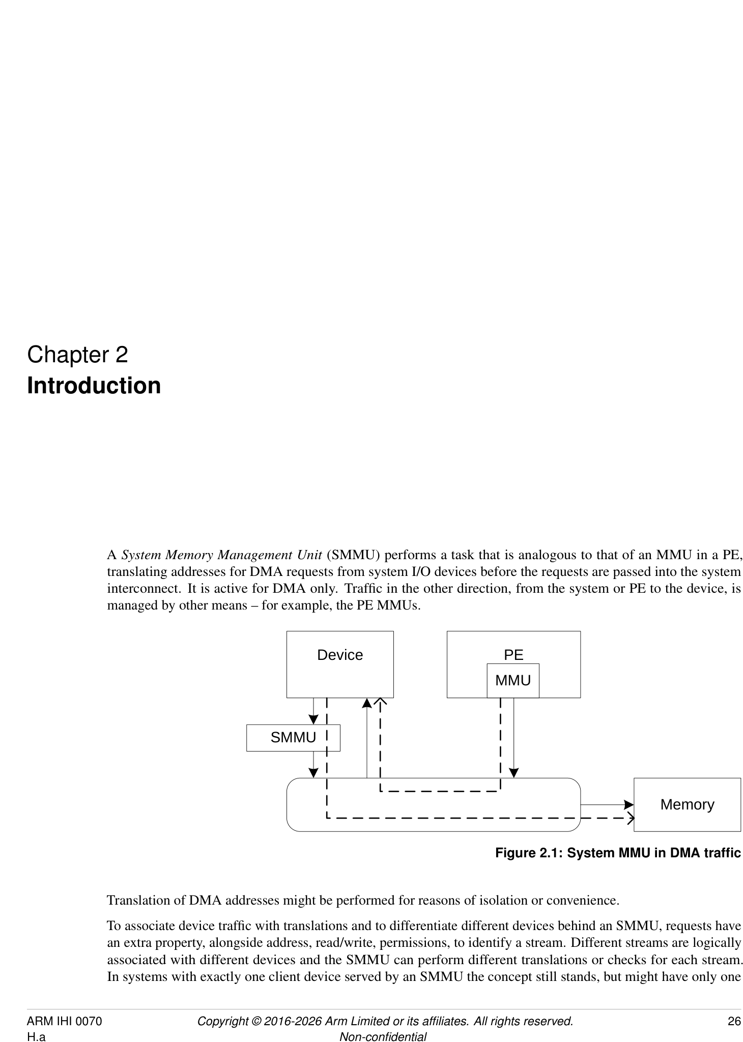
Translation of DMA addresses might be performed for reasons of isolation or convenience.
To associate device traffic with translations and to differentiate different devices behind an SMMU, requests have an extra property, alongside address, read/write, permissions, to identify a stream. Different streams are logically associated with different devices and the SMMU can perform different translations or checks for each stream. In systems with exactly one client device served by an SMMU the concept still stands, but might have only one
stream.
Several SMMUs might exist within a system. An SMMU might translate traffic from just one device or a set of devices.
The SMMU supports two stages of translation in a similar way to PEs supporting the Virtualization Extensions [2]. Each stage of translation can be independently enabled. An incoming address is logically translated from VA to IPA in stage 1, then the IPA is input to stage 2 which translates the IPA to the output PA. Stage 1 is intended to be used by a software entity to provide isolation or translation to buffers within the entity, for example DMA isolation within an OS. Stage 2 is intended to be available in systems supporting the Virtualization Extensions and is intended to virtualize device DMA to guest VM address spaces. When both stage 1 and stage 2 are enabled, the translation configuration is called nested .
2.1 History
-
SMMUv1 supports a modest number of contexts/streams configured using registers, limiting scalability.
-
SMMUv2 extends SMMUv1 with Armv8-A translation table formats, large addresses, with the same limited number of contexts and streams.
SMMUv1 and SMMUv2 map an incoming data stream onto one of many register-based context banks which indicate translation tables and translation configuration to use. The context bank might also indicate a second context bank for nested translation of a second stage (stage 1 and stage 2). The stream is identified using an externally-generated ID supplied with each transaction. A second ID might be supplied to determine the Security state of a stream or group of streams. The use of register-based configuration limits the number of context banks and support of thousands of concurrent contexts is not possible.
Because live data streams might potentially present transactions at any time, the available number of contexts limits the number of streams that might be concurrently enabled. For example, a system might have 1000 network interfaces that might all be idle but whose DMA might be triggered by incoming traffic at any time. The streams must be constantly available to function correctly. It is usually not possible to time-division multiplex a context between many devices requiring service.
The SMMU programming interface register SMMU_AIDR indicates which SMMU architecture version the SMMU implements, as follows:
-
If SMMU_AIDR[7:0] == 0x00, the SMMU implements SMMUv3.0.
-
If SMMU_AIDR[7:0] == 0x01, the SMMU implements SMMUv3.1.
-
If SMMU_AIDR[7:0] == 0x02, the SMMU implements SMMUv3.2.
-
If SMMU_AIDR[7:0] == 0x03, the SMMU implements SMMUv3.3.
-
If SMMU_AIDR[7:0] == 0x04, the SMMU implements SMMUv3.4.
-
If SMMU_AIDR[7:0] == 0x05, the SMMU implements SMMUv3.5.
Unless specified otherwise, all architecture behaviors apply equally to all minor revisions of SMMUv3.
2.2 SMMUv3.0 features
SMMUv3 provides feature to complement PCI Express [1] Root Complexes and other potentially large I/O systems by supporting large numbers of concurrent translation contexts.
-
Memory-based configuration structures to support large numbers of streams.
-
Implementations might support only stage 1, only stage 2 or both stages of translation. This capability, and other IMPLEMENTATION SPECIFIC options, can be discovered from the register interface.
-
Up to 16-bit ASIDs.
-
Up to 16-bit VMIDs [2].
-
Address translation and protection according to Armv8.1 [2] Virtual Memory System Architecture. SMMU translation tables shareable with PEs, allowing software the choice of sharing an existing table or creating an SMMU-private table.
-
49-bit VA, matching Armv8-A’s 2×48-bit translation table input sizes.
Support for the following is optional in an implementation:
-
Either stage 1 or stage 2.
-
Stage 1 and 2 support for the VMSAv8-32 LPAE and VMSAv8-64 translation table format.
-
Secure stream support.
-
Broadcast TLB invalidation.
-
Hardware Translation Table Update (HTTU) of Access flag and dirty state of a page. An implementation might support update of the Access flag only, update of both the Access flag and the dirty state of the page, or no HTTU.
-
PCIe ATS [1] and PRI, when used with compatible Root Complex.
-
16KB and 64KB page granules. However, the presence of 64KB page granules at both stage 1 and stage 2 is suggested to align with the PE requirements in the Server Base System Architecture.
Because the support of large numbers of streams using in-memory configuration causes the SMMUv3 programming interface to be significantly different from that of SMMUv2 [4], SMMUv3 is not designed to be backward-compatible with SMMUv2.
| SMMU feature name | Description | A-profle feature name |
|---|---|---|
| SMMUv3.0-ASID16 | Support for 16-bit ASIDs, see | |
| SMMU_IDR0.ASID16. | ||
| SMMUv3.0-ATS | Support for PCIe ATS, seeSMMU_IDR0.ATS | |
| and [1]. | ||
| SMMUv3.0-BTM | Support for broadcast of TLB maintenance, see | |
| SMMU_IDR0.BTM. | ||
| SMMUv3.0-HAD | Support for disabling hierarchical attributes in | FEAT_HPDS |
| translation tables, seeSMMU_IDR3.HAD. | ||
| SMMUv3.0-HTTUA | Support for hardware translation table Access and | FEAT_HAFDBS |
| SMMUv3.0-HTTUD | dirty state, seeSMMU_IDR0.HTTU. | |
| SMMUv3.0-Hyp | Hypervisor stage 1 contexts supported, see | FEAT_VHE EL2 |
| SMMU_IDR0.HYP. | ||
| SMMUv3.0-GRAN4K | Support for 4KB translation granule, see | |
| SMMU_IDR5.GRAN4K. | ||
| SMMUv3.0-GRAN16K | Support for 16KB translation granule, see | |
| SMMU_IDR5.GRAN16K. | ||
| SMMUv3.0-GRAN64K | Support for 64KB translation granule, see | |
| SMMU_IDR5.GRAN64K. |
| SMMU feature name | Description | A-profle feature name |
|---|---|---|
| SMMUv3.0-PRI | Support for PCIe Page Request Interface, see | |
| SMMU_IDR0.PRI and [1]. | ||
| SMMUv3.0-S1P | Support for Stage 1 translations, see | |
| SMMU_IDR0.S1P. | ||
| SMMUv3.0-S2P | Support for Stage 2 translations, see | |
| SMMU_IDR0.S2P. | ||
| SMMUv3.0-SECURE_IMPL | Support for Secure and Non-secure streams, see | |
| SMMU_S_IDR1.SECURE_IMPL. | ||
| SMMUv3.0-TTFAA32 | Support for VMSAv8-32 LPAE format translation | |
| tables. | ||
| SMMUv3.0-TTFAA64 | Support for VMSAv8-64 format translation tables. | |
| SMMUv3.0-VMID16 | Support for 16-bit VMID, see | FEAT_VMID16 |
| SMMU_IDR0.VMID16. | ||
| SMMUv3.0-ATOS | Support for address translation operation registers, | |
| seeSMMU_IDR0.ATOS. | ||
| SMMUv3.0-VATOS | Support for stage 1-only address translation | |
| operation registers, seeSMMU_IDR0.VATOS. |
SMMUv3.0 also includes a Performance Monitor Counter Group extension, with the following optional features:
| SMMU PMCG feature name | Description |
|---|---|
| SMMU_PMCGv3.0-SID_FILTER_TYPE_ALL | Support for fltering of event counts on a global or per-event basis. See |
| SMMU_PMCG_CFGR.SID_FILTER_TYPE. | |
| SMMU_PMCGv3.0-CAPTURE | Support for software-initiated capture of counter values. See |
| SMMU_PMCG_CFGR.CAPTURE. | |
| SMMU_PMCGv3.0-MSI | Support for PMCG-originated MSIs. SeeSMMU_PMCG_CFGR.MSI. |
| SMMU_PMCGv3.0-RELOC_CTRS | Support for exposing PMCG event counts in independent page of address |
| space. SeeSMMU_PMCG_CFGR.RELOC_CTRS. | |
| SMMU_PMCGv3.0-SECURE_IMPL | Support for counting events from more than one Security state. See |
| SMMU_PMCG_SCRbit [31]. |
2.3 SMMUv3.1 features
SMMUv3.1 extends the base SMMUv3.0 architecture with the following features:
-
Support for PEs implementing Armv8.2-A:
-
Support for 52-bit VA, IPA, and PA.
- [Note:][An][SMMUv3.1][implementation][is][not][required][to][support][52-bit][addressing,][but][the] SMMUv3.1 architecture extends fields to allow an implementation the option of doing so.
-
Page-Based Hardware Attributes (PBHA).
-
EL0 vs EL1 execute-never controls in stage 2 translation tables.
-
Note: Armv8.2 introduces a Common not Private (CnP) concept to the PE which does not apply to the SMMU architecture, because all SMMU translations are treated as common.
-
-
Support for transactions that perform cache-stash or destructive read side effects.
-
Performance Monitor Counter Group (PMCG) error status.
| SMMU feature name | Description | A-profle feature name |
|---|---|---|
| SMMUv3.1-XNX | Provides support for translation table stage 2 | FEAT_XNX |
| Unprivileged Execute-never, see | ||
| SMMU_IDR3.XNX. | ||
| SMMUv3.1-TTPBHA | Provides support for translation table page-based | FEAT_HPDS2 |
| hardware attributes, seeSMMU_IDR3.PBHA. | ||
| SMMUv3.1-VAX | Support for large Virtual Address space, see | FEAT_LVA |
| SMMU_IDR5.VAX. | ||
| SMMUv3.1-LPA | Support for large Physical Address space, see | FEAT_LPA |
| SMMU_IDR5.OAS. |
2.4 SMMUv3.2 features
SMMUv3.2 extends the SMMUv3.1 architecture with the following features:
• Support for PEs implementing Armv8.4-A [2]: – Support for Memory System Resource Partitioning and Monitoring (MPAM) [3]. *[Note:][Support for MPAM is optional in SMMUv3.2.] – Secure EL2 and Secure stage 2 translation. *[All previous rules about Secure streams being stage 1 only are removed.] – Stage 2 control of memory types and cacheability. – Small translation tables support. – Range-based TLB invalidation and Level Hint. – Translation table updates without break-before-make. • Introduction of a Virtual Machine Structure for describing some per-VM configuration.
| SMMU feature name | Description | A-profle feature name |
|---|---|---|
| SMMUv3.2-BBML1 | Support for change in size of translation table | FEAT_BBML1, FEAT_BBML2 |
| SMMUv3.2-BBML2 | mappings, seeSMMU_IDR3.BBML. | |
| SMMUv3.2-RIL | Support for range-based TLB invalidation and | FEAT_TTL, FEAT_TLBIRANGE |
| level hint, seeSMMU_IDR3.RIL. | ||
| SMMUv3.2-SecEL2 | Support for Secure EL2 and Secure stage 2 | FEAT_SEL2 |
| translations, seeSMMU_S_IDR1.SEL2. | ||
| SMMUv3.2-STT | Support for small translation tables, see | FEAT_TTST |
| SMMU_IDR3.STT. | ||
| SMMUv3.2-MPAM | Support for Memory System Resource | FEAT_MPAM |
| Partitioning and Monitoring, see | ||
| SMMU_IDR3.MPAM. | ||
| SMMUv3.2-S2FWB | Support for stage 2 forced Write-Back, see | FEAT_S2FWB |
| SMMU_IDR3.FWB. |
SMMUv3.2 also introduces the following optional features to the PMCG extension:
| SMMU PMCG feature name | Description |
|---|---|
| SMMU_PMCGv3.2-MPAM | Support for associating PMCG-originated MSIs with specifc MPAM |
| PARTID and PMG values. SeeSMMU_PMCG_CFGR.MPAM. |
2.5 SMMUv3.3 features
SMMUv3.3 extends the SMMUv3.2 architecture with the following features:
-
Support for features of PEs implementing Armv8.5 [2]:
-
E0PD feature, equivalent to FEAT_E0PD introduced in Armv8.5.
-
Protected Table Walk (PTW) behavior alignment with Armv8.
-
MPAM_NS mechanism, for alignment with FORCE_NS feature [3].
-
Requirements for interaction with the Memory Tagging Extension [2].
-
-
Enhanced Command queue interface for reducing contention when submitting Commands to the SMMU.
-
• Support for recording non-Translation-related events for ATS Translation Requests.
-
Guidelines for RAS error recording.
| SMMU feature name | Description | A-profle feature name |
|---|---|---|
| SMMUv3.3-E0PD Mandatory | Support for preventing EL0 access to halves of | FEAT_E0PD |
| address maps. SeeSMMU_IDR3.E0PD. | ||
| SMMUv3.3-PTWNNC | Support for treating table walks to Device | |
| Mandatory | memory as Normal Non- cacheable. See | |
| SMMU_IDR3.PTWNNC. | ||
| SMMUv3.3-MPAM_NS | Support for Secure transactions using Non-secure | |
| Optional | PARTID space. See | |
| SMMU_S_MPAMIDR.HAS_MPAM_NS. | ||
| SMMUv3.3-ECMDQ Optional | Support for Enhanced Command queue interfaces. | |
| SeeSMMU_IDR1.ECMDQ. | ||
| SMMUv3.3-SEC_ECMDQ | Support for Enhanced Command queue interfaces | |
| Optional | for Secure state. SeeSMMU_S_IDR0.ECMDQ. | |
| SMMUv3.3-ATSRECERR | Support for recording events on confguration | |
| Optional | errors for ATS translation requests. See | |
| SMMU_IDR0.ATSRECERR. |
SMMUv3.3 also introduces the following optional features to the PMCG extension:
| SMMU PMCG feature name | Description |
|---|---|
| SMMU_PMCGv3.3-FILTER_MPAM | Support for fltering event counts by MPAM attributes. See |
| SMMU_PMCG_CFGR.FILTER_PARTID_PMG. | |
| SMMU_PMCGv3.3-MPAM_NS | Support for issuing PMCG MSIs for Secure state, associated with a |
| Non-secure MPAM PARTID. See | |
| SMMU_PMCG_S_MPAMIDR.HAS_MPAM_NS. |
2.6 SMMU for RME features
SMMU for RME introduces support for Granule Protection Checks, for interoperability with PEs that implement FEAT_RME [2].
There are two aspects to RME support for SMMU:
-
Whether the SMMU has the Root programming interface and can perform Granule Protection Checks. This is advertised with SMMU_ROOT_IDR0.ROOT_IMPL == 1.
-
Whether the SMMU has RME-related changes exposed to the Secure and Non-secure programming interfaces. This is advertised with SMMU_IDR0.RME_IMPL == 1.
Any SMMU behaviors specified as applying to an SMMU with RME apply to an SMMU implementation with SMMU_ROOT_IDR0.ROOT_IMPL == 1.
An SMMU with RME must have SMMU_ROOT_IDR0.ROOT_IMPL == 1. It is permitted for an SMMU with RME to have SMMU_IDR0.RME_IMPL == 0.
An SMMU with RME also implements SMMUv3.2 or later.
An SMMU with SMMU_IDR0.RME_IMPL == 1 does not support the EL3 StreamWorld. This means that:
-
An STE with STRW configured for EL3 is ILLEGAL and results in C_BAD_STE.
-
The commands CMD_TLBI_EL3_ALL, CMD_TLBI_EL3_VA result in CERROR_ILL.
-
The SMMU is not required to perform any invalidation on receipt of a broadcast TLBI for EL3.
Note: The value of SMMU_IDR0.RME_IMPL does not affect support for other features associated with Secure state.
See also 3.25 Granule Protection Checks .
| SMMU RME feature name | Description | A-profle feature name |
|---|---|---|
| SMMUv3.3-RME_ROOT_IMPL | Support for the Root programming interface. See | FEAT_RME |
| SMMU_ROOT_IDR0.ROOT_IMPL. | ||
| SMMUv3.3-RME_IMPL | Support for visibility of GPC faults to the Non-secure, | FEAT_RME |
| Secure and Realm programming interfaces, if supported. | ||
| SeeSMMU_IDR0.RME_IMPL. | ||
| SMMUv3.3-RME_BGPTM | Support for broadcast TLBI PA operations. See | FEAT_RME |
| SMMU_ROOT_IDR0.BGPTM. | ||
| SMMUv3.3-RME_RGPTM | Support for register TLBI by PA. See | |
| SMMU_ROOT_IDR0.RGPTM. |
An SMMU with RME implements either SMMUv3.3-RME_ROOT_IMPL or SMMUv3.3-RME_IMPL.
2.7 SMMU for RME DA features
SMMU for RME DA introduces features that enable the association between devices and software executing in the Realm Security state. See [2].
Any SMMU behavior specified as applying to an SMMU with RME DA apply to an SMMU implementation with SMMU_ROOT_IDR0.REALM_IMPL == 1. This means that in such implementations, Realm programming interface is supported.
| SMMU RME DA feature | ||
|---|---|---|
| name | Description | A-profle feature name |
| SMMUv3.3-RME_DA | Support for the Realm programming interface. See | FEAT_RME |
| SMMU_ROOT_IDR0.REALM_IMPL. | ||
| SMMUv3.3-MEC_R | Support for the RME Memory Encryption Contexts | FEAT_MEC |
| extension. SeeSMMU_R_IDR3.MEC. | ||
| SMMUv3.3-DPT_R | Support for Device Permission Table in Realm state. See | |
| SMMU_R_IDR3.DPT. | ||
| SMMUv3.3-DPT_NS | Support for Device Permission Table in Non-secure state. | |
| SeeSMMU_IDR3.DPT. |
An SMMU with RME DA implements SMMUv3.3-RME_DA.
2.7.1 Required features
An SMMU with SMMU_ROOT_IDR0.REALM_IMPL == 1 implements all the mandatory features from SMMUv3.3, including the following requirements:
| Register feld | Value | Notes |
|---|---|---|
| SMMU_IDR3.PTWNNC | 1 | Mandatory from SMMUv3.3 onwards. |
| SMMU_IDR3.E0PD | 1 | Mandatory from SMMUv3.3 onwards. |
| SMMU_IDR3.STT | 1 | Mandatory because of Secure EL2 requirement. |
| SMMU_IDR3.FWB | 1 | Mandatory from SMMUv3.2. |
| SMMU_IDR3.XNX | 1 | Mandatory from SMMUv3.1. |
| SMMU_IDR3.HAD | 1 | Mandatory from SMMUv3.1. |
An SMMU with SMMU_ROOT_IDR0.REALM_IMPL == 1 additionally has the following features:
| Register feld | Value | Notes |
|---|---|---|
| SMMU_IDR0.Hyp | 1 | Required for EL2. |
| SMMU_IDR0.S1P | 1 | Required for stage 1 translation. |
| SMMU_IDR0.S2P | 1 | Required for stage 2 translation. |
| SMMU_IDR0.TTF | 0b10 | VMSAv8-64 only. |
| SMMU_R_IDR3.DPT | - | Support for DPT is strongly recommended. |
| Register feld | Value | Notes |
|---|---|---|
| SMMU_IDR0.NS1ATS | - | If ATS is supported and DPT is not supported, then split-stage ATS must be supported. |
| SMMU_IDR0.COHACC | 1 | Required for coherent access to RMM-managed tables. |
| SMMU_IDR0.BTM | - | Support for broadcast TLB maintenance is strongly recommended. |
| SMMU_IDR0.HTTU | - | Support for Hardware update of Access Flag and Dirty state is strongly recommended. |
| SMMU_IDR0.RME_IMPL | 1 | Granule Protection Check faults are visible to Non-secure, Realm and Secure states. |
| SMMU_IDR3.BBML | 0b10 | Level 2 support is required. |
| SMMU_ROOT_IDR0.ROOT_IMPL | 1 | SMMU must be able to perform Granule Protection Checks. |
2.8 SMMUv3.4 features
SMMUv3.4 extends the SMMUv3.3 architecture with the following features:
• Support for features of PEs implementing Armv8.7 [2]: – 52-bit virtual and physical address spaces when using 4KB and 16KB translation granule sizes. – Enhanced PAN mechanism. – Requirements for interoperability with PEs that implement FEAT_XS. See 3.17.8 TLBInXS maintenance operations . • Support for features of PEs implementing Armv8.9 [2]: – Stage 1 and Stage 2 permission indirections. – Stage 2 permission overlays. – Translation hardening. – Attribute Index Enhancement. – 128-bit descriptors and 56-bit address spaces. – Table descriptor Access flag. – Stage 2 MemAttr NoTagAccess encodings. • Support for the PASID TLP prefix for use on ATS Translated transactions. • Deprecation of stashing translation information in ATS address fields. • Deprecation of InD and PnU as output attributes. • Deprecation of the SMMU_PMCG_PMAUTHSTATUS register.
| SMMU feature name | Description | A-profle feature name |
|---|---|---|
| SMMUv3.4-LPA2 Optional | Support for 52-bits of virtual and physical address | FEAT_LPA2 |
| space when using the 4KB and 16KB translation | ||
| granule sizes. SeeSMMU_IDR5.DS. | ||
| SMMUv3.4-PAN3 Optional | Support for the Enhanced PAN mechanism. See | FEAT_PAN3 |
| SMMU_IDR3.EPAN. | ||
| SMMUv3.4-THE Optional | Support for translation hardening extension. See | FEAT_THE |
| SMMU_IDR3.THE. | ||
| SMMUv3.4-S1PIE Optional | Support for stage 1 permission indirections. See | FEAT_S1PIE |
| SMMU_IDR3.S1PI. | ||
| SMMUv3.4-S2PIE Optional | Support for stage 2 permission indirections. See | FEAT_S2PIE |
| SMMU_IDR3.S2PI. | ||
| SMMUv3.4-S2POE Optional | Support for stage 2 permission overlays. See | FEAT_S2POE |
| SMMU_IDR3.S2PO. | ||
| SMMUv3.4-D128 Optional | Support for 128-bit translation table descriptors. See | FEAT_D128, FEAT_LVA3, 56-bit |
| SMMU_IDR5.D128, andSMMU_IDR5.{OAS, | physical addresses | |
| VAX}. | ||
| SMMUv3.4-AIE Optional | Support for stage 1 Attribute Index Enhancement. See | FEAT_AIE |
| SMMU_IDR3.AIE. | ||
| SMMUv3.4-HAFT Optional | Support for Table descriptor Access fags. See | FEAT_HAFT |
| SMMU_IDR0.HTTU. | ||
| SMMUv3.4-MTE_PERM | Support for stage 2 MemAttr NoTagAccess encodings. | FEAT_MTE_PERM |
| Mandatory | SeeSMMU_IDR3.MTEPERM. | |
| SMMUv3.4-PASIDTT | Support for use of the PASID TLP prefx on ATS | |
| Optional | Translated transactions. SeeSMMU_IDR3.PASIDTT. |
2.9 SMMUv3.5 features
SMMUv3.5 extends the SMMUv3.4 architecture with the following features:
-
Support for features of PEs implementing Armv9.5 [2]:
-
Above PPS All Access.
-
– Non-Secure only (NSO) GPI encoding.
-
– Interoperability with PEs with FNGx control fields.
-
– Hardware dirty state tracking structure (HDBSS).
-
– Hardware accelerator for cleaning dirty state (HACDBS).
-
– TLBI VMALL for Dirty state.
-
GPT scaling features.
-
Granular Data Isolation.
-
-
Support for Direct-mode Enhanced Command Queues.
-
• Support for virtual to physical StreamID translation.
-
Support for software control of memory type attribute transformation.
| SMMU feature name | Description | A-profle feature name |
|---|---|---|
| SMMUv3.5-RME_APPSAA | Support for Above PPS All Access. See | FEAT_RME_GPC2 |
| Optional | SMMU_ROOT_IDR0.APPSAA. | |
| SMMUv3.5-RME_NSO | Support for the Non-Secure only (NSO) GPI encoding. | FEAT_RME_GPC2 |
| Optional | SeeSMMU_ROOT_IDR0.NSO. | |
| SMMUv3.5-FNG Mandatory | Support for interoperability with a PE with FNGx | FEAT_ASID2 |
| control felds. SeeSMMU_IDR3.FNG. | ||
| SMMUv3.5-HDBSS | Support for hardware dirty state tracking structure. See | FEAT_HDBSS |
| Optional | SMMU_IDR3.HDBSS. | |
| SMMUv3.5-HACDBS | Support for hardware accelerator for cleaning dirty | FEAT_HACDBS |
| Optional | state. SeeSMMU_IDR3.HACDBS. | |
| SMMUv3.5-TLBIW | Support TLBI VMALL for Dirty state. See | FEAT_TLBIW |
| Optional | SMMU_IDR3.TLBIW. | |
| SMMUv3.5-RME_GPTS | Support for the GPT scaling features. See | FEAT_RME_GPC3 |
| Optional | SMMU_ROOT_IDR0.GPTS. | |
| SMMUv3.5-RME_GDI | Support for Granular Data Isolation. See | FEAT_RME_GDI |
| Optional | SMMU_ROOT_IDR0.GDI. | |
| SMMUv3.5-DCMDQ | Support for Direct Enhanced Command Queues. See | |
| Optional | SMMU_IDR6.DCMDQ. | |
| SMMUv3.5-VSID Optional | Support for virtual to physical StreamID. translation. | |
| SeeSMMU_IDR6.VSID. | ||
| SMMUv3.5-MTCOMB | Support for software control of memory type attribute | |
| Mandatory | transformation. SeeSMMU_IDR3.MTCOMB. |
- 2.10. Permitted implementation of subsets of SMMUv3.x and SMMUv3.(x+1) architectural features
2.10 Permitted implementation of subsets of SMMUv3.x and SMMUv3.(x+1) architectural features
An SMMUv3.x compliant implementation can include any arbitrary subset of the architectural features of SMMUv3.(x+1), subject only to those constraints that require that certain features be implemented together.
An SMMUv3.x compliant implementation cannot include any features of SMMUv3.(x+2) or later. Arm strongly recommends that implementations use the latest version available at design time.
2.11 System placement
PEs
M StreamID StreamID
Incoming
S M S device M I/O S M Device
S traffic  interconnect ‘in’ S S 1
SMMU
M Prog I/F S
S I/O M M Device
‘out’
M Outgoing device traffic  interconnect M S 2
System  StreamID RequesterID
interconnect
Incoming PCIe
M S PCIe M Device 1
traffic ATC
S PCIe Switch
SMMU
Root
Complex
M Prog I/F S PCIe
S Device 2
ATC
M Outgoing PCIe traffic
ATS
M S Memory
Port
Root
Figure 2.2: SMMU placement in an example system
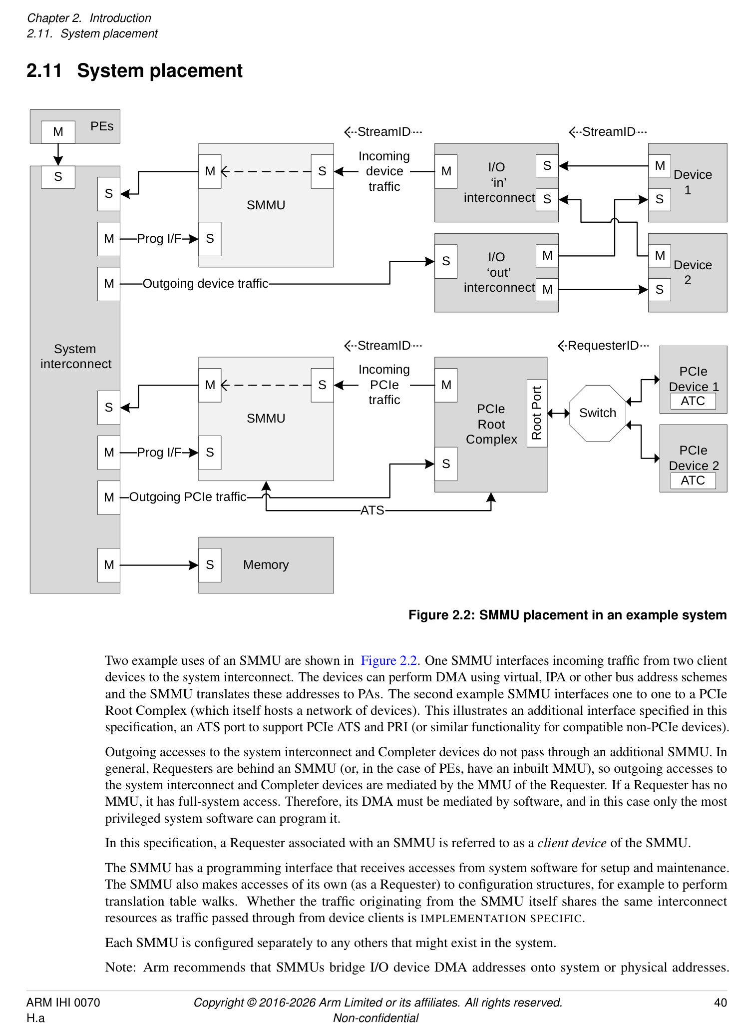
Two example uses of an SMMU are shown in Figure 2.2. One SMMU interfaces incoming traffic from two client devices to the system interconnect. The devices can perform DMA using virtual, IPA or other bus address schemes and the SMMU translates these addresses to PAs. The second example SMMU interfaces one to one to a PCIe Root Complex (which itself hosts a network of devices). This illustrates an additional interface specified in this specification, an ATS port to support PCIe ATS and PRI (or similar functionality for compatible non-PCIe devices).
Outgoing accesses to the system interconnect and Completer devices do not pass through an additional SMMU. In general, Requesters are behind an SMMU (or, in the case of PEs, have an inbuilt MMU), so outgoing accesses to the system interconnect and Completer devices are mediated by the MMU of the Requester. If a Requester has no MMU, it has full-system access. Therefore, its DMA must be mediated by software, and in this case only the most privileged system software can program it.
In this specification, a Requester associated with an SMMU is referred to as a client device of the SMMU.
The SMMU has a programming interface that receives accesses from system software for setup and maintenance. The SMMU also makes accesses of its own (as a Requester) to configuration structures, for example to perform translation table walks. Whether the traffic originating from the SMMU itself shares the same interconnect resources as traffic passed through from device clients is IMPLEMENTATION SPECIFIC.
Each SMMU is configured separately to any others that might exist in the system.
Note: Arm recommends that SMMUs bridge I/O device DMA addresses onto system or physical addresses.
Arm recommends that SMMUs are placed between a device Requester port (or I/O interconnect) and system interconnect. Generally, Arm recommends that SMMUs are not placed in series and that the path of an SMMU to memory or other Completer devices does not pass through another SMMU, whether for fetch of SMMU configuration data or client transactions.
Note: Interconnect-specific channels to support cache coherency are not shown in Figure 2.2.
The SMMU interface to the system interconnect is intended to be IO-coherent, and provide either IO-coherent or fully-coherent access for the client devices of the SMMU.
Note: It is feasible to implement an SMMU as part of a complex device containing fully coherent caches in the same way that the MMU of a PE is paired to fully coherent PE caches. Practically, this means the caches must be tagged with physical addresses.
PCIe  PCIe
Device 0 Device 1
ATC ATC
Switch
Device Device Device
Root
0 1 2
Port
Device Device
0 1 PCIe
Root
I/O interconnect Complex
Complex device  I/O interconnect
with embedded  ‘Smart’
MMU Distributed SMMU C device
ATS
Control &
Embedded Monolithic
translation  TLB TLB
SMMU A SMMU B table walk TLB
System interconnect
Memory
Figure 2.3: Example SMMU implementations
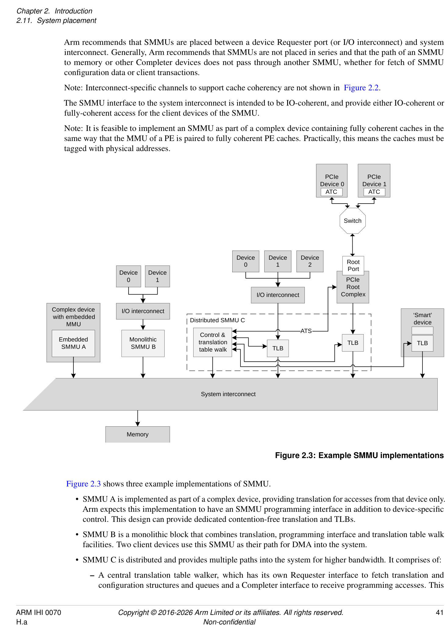
Figure 2.3 shows three example implementations of SMMU.
-
SMMU A is implemented as part of a complex device, providing translation for accesses from that device only. Arm expects this implementation to have an SMMU programming interface in addition to device-specific control. This design can provide dedicated contention-free translation and TLBs.
-
SMMU B is a monolithic block that combines translation, programming interface and translation table walk facilities. Two client devices use this SMMU as their path for DMA into the system.
-
SMMU C is distributed and provides multiple paths into the system for higher bandwidth. It comprises of:
- A central translation table walker, which has its own Requester interface to fetch translation and configuration structures and queues and a Completer interface to receive programming accesses. This
unit might contain a macro-TLB and caches of configuration.
- [The central translation table walker also provides an ATS interface to the Root Complex, so that the] PCIe Devices can use ATS to make translation requests through to the central unit.
-
Remote TLB units which, on a miss, make translation requests to the central unit and cache the results locally. Two units are shown, supporting a set of three devices through one port, and a PCIe Root Complex through another.
-
Finally, a smart device is shown, which embeds a TLB and makes translation requests to the central unit of SMMU C. To software, this looks identical to a simple device connected behind a discrete TLB unit. This design provides a dedicated TLB for the device, but uses the programming interface and translation facilities of the central unit, reducing complexity of the device.
In all cases, it appears to software as though a device is connected behind a logically-separate SMMU (similar to Device 0/1 on SMMU B). All implementations give the illusion of simple read/write transactions arriving from a client device to a discrete SMMU, even if physically it is the device performing the read/write transactions directly into the system, using translations provided by an SMMU.
Note: This allows a single SMMU driver to be used for radically different SMMU implementations.
Note: Devices might integrate a TLB, or whole SMMU, for performance reasons, but a closely-coupled TLB might also be used to provide physical addresses suitable for fully coherent device caches.
Regardless of the implementation style, this specification uses the abstraction of client device transactions arriving at an SMMU. The boundary of SMMU might contain a single module or several distributed subcomponents but these must all behave consistently.
Operation
Chapter 3 Operation
3.1 Software interface
The SMMU has three interfaces that software uses:
-
Memory-based data structures to map devices to translation tables which are used to translate client device addresses.
-
Memory-based circular buffer queues. These are a Command queue for commands to the SMMU, an Event queue for event/fault reports from the SMMU, and a PRI queue for receipt of PCIe page requests.
- Note: The PRI queue is only present on SMMUs supporting PRI services. This additional queue allows processing of PRI requests from devices separate from event or fault reports.
-
A set of registers, for each supported Security state, for discovery and SMMU-global configuration.
The registers indicate the base addresses of the structures and queues, provide feature detection and identification registers and a global control register to enable queue processing and translation of traffic. When Secure state is supported, an additional register set exists to allow Secure software to maintain Secure device structures, issue commands on a second Secure Command queue and read Secure events from a Secure Event queue.
In virtualization scenarios allowing stage 1 translation, a guest OS is presented with the same programming interface and therefore believes it is in control of a real SMMU (albeit stage 1-only) with the same format of Command, Event, and optionally PRI, queues, and in-memory data structures.
Certain fields in architected SMMU registers and structures are marked as IMPLEMENTATION DEFINED. The content of these fields is specific to the SMMU implementation, but implementers must not use these fields in such a way that a generic SMMUv3 driver becomes unusable. Unless a driver has extended knowledge of particular IMPLEMENTATION DEFINED fields or features, the driver must treat all such fields as Reserved and set them to 0.
An implementation only uses IMPLEMENTATION DEFINED fields to enable extended functionality or features, and remains compatible with generic driver software by maintaining architected behavior when these fields are set to 0.
3.2 Stream numbering
An incoming transaction has an address, size, and attributes such as read/write, Secure/Non-secure, Shareability, Cacheability. If more than one client device uses the SMMU traffic must also have a sideband StreamID so the sources can be differentiated. How a StreamID is constructed and carried through the system is IMPLEMENTATION DEFINED. Logically, a StreamID corresponds to a device that initiated a transaction.
Note: The mapping of a physical device to StreamID must be described to system software.
Arm recommends that StreamID be a dense namespace starting at 0. The StreamID namespace is per-SMMU. Devices assigned the same StreamID but behind different SMMUs are seen to be different sources. A device might emit traffic with more than one StreamID, representing data streams differentiated by device-specific state.
StreamID is of IMPLEMENTATION DEFINED size, between 0 bits and 32 bits.
The StreamID is used to select a Stream Table Entry (STE) in a Stream table, which contains per-device configuration. The maximum size of in-memory configuration structures relates to the maximum StreamID span (see 3.3 Data structures and translation procedure below), with a maximum of 2[StreamIDSize] entries in the Stream table.
Another property, SubstreamID, might optionally be provided to an SMMU implementing stage 1 translation. The SubstreamID is of IMPLEMENTATION DEFINED size, between 0 bits and 20 bits, and differentiates streams of traffic originating from the same logical block to associate different application address translations to each.
Note: An example would be a compute accelerator with 8 contexts that might each map to a different user process, but where the single device has common configuration meaning it must be assigned to a VM whole.
Note: The SubstreamID is equivalent to a PCIe PASID. Because the concept can be applied to non-PCIe systems, it has been given a more generic name in the SMMU. The maximum size of SubstreamID, 20 bits, matches the maximum size of a PCIe PASID.
The incoming transaction flags whether a SubstreamID is supplied and this might differ on a per-transaction basis.
Both of these properties and sizes are discoverable through the SMMU_IDR1 register. See section 16.4 System integration for recommendations on StreamID and SubstreamID sizing.
The StreamID is the key that identifies all configuration for a transaction. A StreamID is configured to bypass or be subject to translation and such configuration determines which stage 1 or stage 2 translation to apply. The SubstreamID provides a modifier that selects between a set of stage 1 translations indicated by the StreamID but has no effect on the stage 2 translation which is selected by the StreamID only.
A stage 2-only implementation does not take a SubstreamID input. An implementation with stage 1 is not required to support substreams, therefore is not required to take a SubstreamID input.
The SMMU optionally supports Secure state and, if supported, the StreamID input to the SMMU is qualified by a SEC_SID flag that determines whether the input StreamID value refers to the Secure or Non-secure StreamID namespace. A Non-secure StreamID identifies an STE within the Non-secure Stream table and a Secure StreamID identifies an STE within the Secure Stream table. In this specification, the term StreamID implicitly refers to the StreamID disambiguated by SEC_SID (if present) and does not refer solely to a literal StreamID input value (which would be associated with two STEs when Secure state is supported) unless explicitly stated otherwise. See section 3.10.2 Support for Secure state .
Arm expects that, for PCI, StreamID is generated from the PCI RequesterID so that StreamID[15:0] == RequesterID[15:0]. When more than one PCIe hierarchy is hosted by one SMMU, Arm recommends that the 16-bit RequesterID namespaces are arranged into a larger StreamID namespace by using upper bits of StreamID to differentiate the contiguous RequesterID namespaces, so that StreamID[N:16] indicates which Root Complex (PCIe domain/segment) is the source of the stream source. In PCIe systems, the SubstreamID is intended to be directly provided from the PASID [1] in a one to one fashion.
Therefore, for SMMU implementations intended for use with PCI clients, supported StreamID size must be at least 16 bits.
3.3 Data structures and translation procedure
The SMMU uses a set of data structures in memory to locate translation data. Registers hold the base addresses of the initial root structure, the Stream table. An STE contains stage 2 translation table base pointers, and also locates stage 1 configuration structures, which contain translation table base pointers. A Context Descriptor (CD) represents stage 1 translation, and a Stream Table Entry represents stage 2 translation.
Therefore, there are two distinct groups of structures used by the SMMU:
-
Configuration structures, which map from the StreamID of a transaction (a device originator identifier) to the translation table base pointers, configuration, and context under which the translation tables are accessed.
-
Translation table structures that are used to perform the VA to IPA and IPA to PA translation of addresses for stage 1 and stage 2, respectively.
The procedure for translation of an incoming transaction is to first locate configuration appropriate for that transaction, identified by its StreamID and, optionally, SubstreamID, and then to use that configuration to locate translations for the address used.
The first step in dealing with an incoming transaction is to locate the STE, which tells the SMMU what other configuration it requires.
Conceptually, an STE describes configuration for a client device in terms of whether it is subject to stage 1 or stage 2 translation or both. Multiple devices can be associated with a single Virtual Machine, so multiple STEs can share common stage 2 translation tables. Similarly, multiple devices (strictly, streams) might share common stage 1 configuration, therefore multiple STEs could share common CDs.
3.3.1 Stream table lookup
The StreamID of an incoming transaction locates an STE. Two formats of Stream table are supported. The format is set by the Stream table base registers. The incoming StreamID is range-checked against the programmed table size, and a transaction is terminated if its StreamID would otherwise select an entry outside the configured Stream table extent (or outside a level 2 span). See SMMU_STRTAB_BASE_CFG and C_BAD_STREAMID.
The StreamID of an incoming transaction might be qualified by SEC_SID, and this determines which Stream table, or cached copies of that Stream table, is used for lookup. See section 3.10.1 StreamID Security state (SEC_SID) .
3.3.1.1 Linear Stream table
STRTAB_BASE
STE 0
STE 1
STE 2
StreamID[n:0] STE 3
Figure 3.1: Linear Stream table
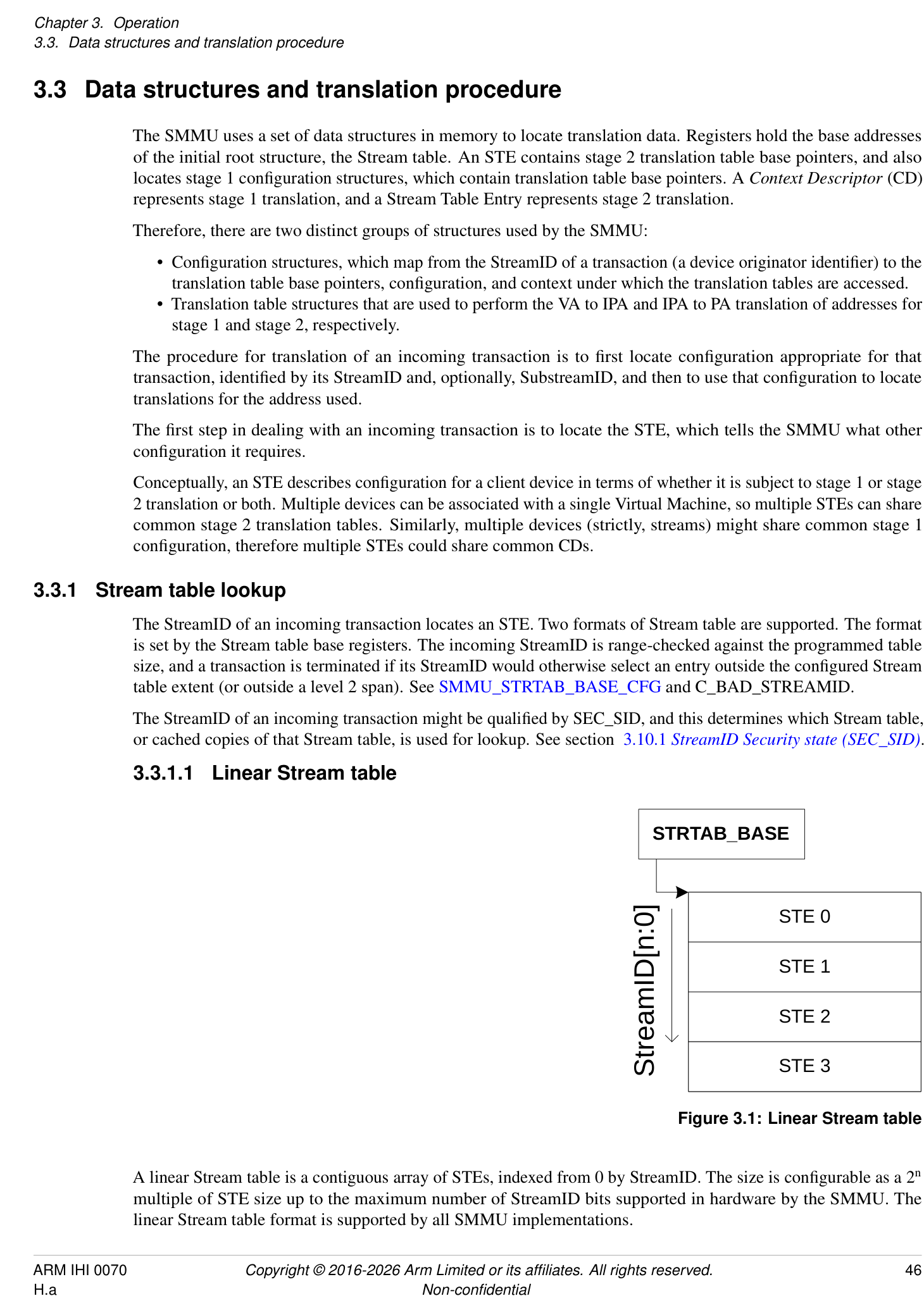
A linear Stream table is a contiguous array of STEs, indexed from 0 by StreamID. The size is configurable as a 2[n] multiple of STE size up to the maximum number of StreamID bits supported in hardware by the SMMU. The linear Stream table format is supported by all SMMU implementations.
3.3.1.2 2-level Stream table
STRTAB_BASE
Addr 0x1000
STE 0x000
Desc 0
Addr 0x2f00
Desc 1
STE 0x001
STE 0x100
STE 0x002
Desc 3
STE 0x101
STE 0x102
STE 0x0fd
STE 0x103
Addr 0x4000
STE 0x0ff
STE 0x300
StreamID[7:0]
StreamID[9:8]
StreamID[1:0]
Figure 3.2: Example Two level Stream table with SPLIT == 8
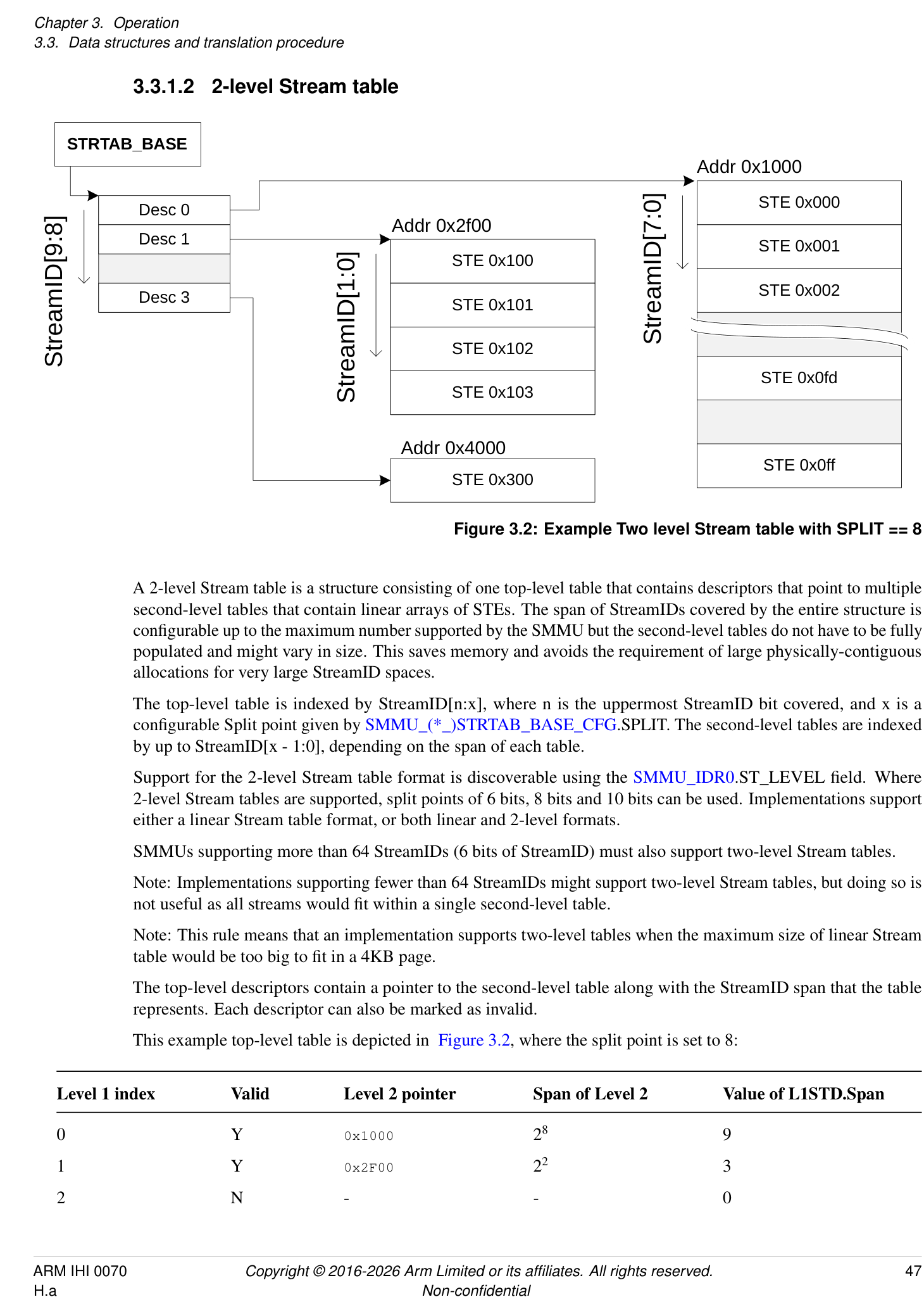
A 2-level Stream table is a structure consisting of one top-level table that contains descriptors that point to multiple second-level tables that contain linear arrays of STEs. The span of StreamIDs covered by the entire structure is configurable up to the maximum number supported by the SMMU but the second-level tables do not have to be fully populated and might vary in size. This saves memory and avoids the requirement of large physically-contiguous allocations for very large StreamID spaces.
The top-level table is indexed by StreamID[n:x], where n is the uppermost StreamID bit covered, and x is a configurable Split point given by SMMU_(*_)STRTAB_BASE_CFG.SPLIT. The second-level tables are indexed by up to StreamID[x - 1:0], depending on the span of each table.
Support for the 2-level Stream table format is discoverable using the SMMU_IDR0.ST_LEVEL field. Where 2-level Stream tables are supported, split points of 6 bits, 8 bits and 10 bits can be used. Implementations support either a linear Stream table format, or both linear and 2-level formats.
SMMUs supporting more than 64 StreamIDs (6 bits of StreamID) must also support two-level Stream tables.
Note: Implementations supporting fewer than 64 StreamIDs might support two-level Stream tables, but doing so is not useful as all streams would fit within a single second-level table.
Note: This rule means that an implementation supports two-level tables when the maximum size of linear Stream table would be too big to fit in a 4KB page.
The top-level descriptors contain a pointer to the second-level table along with the StreamID span that the table represents. Each descriptor can also be marked as invalid.
This example top-level table is depicted in Figure 3.2, where the split point is set to 8:
| Level | 1 | index | Valid | Level 2 pointer | Span of Level 2 | Value of L1STD.Span |
|---|---|---|---|---|---|---|
| 0 | Y | 0x1000 | 28 | 9 | ||
| 1 | Y | 0x2F00 | 22 | 3 | ||
| 2 | N | - | - | 0 |
| Level | 1 | index | Valid | Level 2 pointer | Span of Level 2 | Value of L1STD.Span |
|---|---|---|---|---|---|---|
| 3 | Y | 0x4000 | 20 | 1 |
In this example:
-
StreamIDs 0-1023 (4 × 8-bit level 2 tables) are represented, though not all are valid.
-
StreamIDs 0-255 are configured by the array of STEs at 0x1000 (each of which separately enables the relevant StreamID).
-
StreamIDs 256-259 are configured by the array of STEs at 0x2F00.
-
StreamIDs 512-767 are all invalid.
-
The STE of StreamID 768 is at 0x4000.
A two-level table with a split point of 8 can reduce the memory usage compared to a large and sparse linear table used with PCIe. If the full 256 PCIe bus numbers are supported, the RequesterID or StreamID space is 16-bits. However, because there is usually one PCIe bus for each physical link and potentially one device for each bus, in the worst case a valid StreamID might only appear once every 256 StreamIDs.
Alternatively, a split point of 6 provides 64 bottom-level STEs, enabling use of a 4KB page for each bottom-level table.
Note: Depending on the size of the StreamID space, the L1 Stream table might require allocation of a region of physically-contiguous memory greater than a single granule. This table shows some example sizes for the amount of memory occupied by L1 and L2 Stream tables:
| SIDSIZE | SPLIT | L1 table size | L2 table size |
|---|---|---|---|
| 16 | 6 | 8KB | 4KB |
| 16 | 8 | 2KB | 16KB |
| 16 | 10 | 512B | 64KB |
| 24 | 6 | 2MB | 4KB |
| 24 | 8 | 512KB | 16KB |
| 24 | 10 | 128KB | 64KB |
3.3.2 StreamIDs to Context Descriptors
The STE contains the configuration for each stream indicating:
-
Whether traffic from the device is enabled.
-
Whether it is subject to stage 1 translation.
-
Whether it is subject to stage 2 translation, and the relevant translation tables.
-
Which data structures locate translation tables for stage 1.
If stage 1 is used, the STE indicates the address of one or more CDs in memory using the STE.S1ContextPtr field.
The CD associates the StreamID with stage 1 translation table base pointers (to translate VA into IPA), per-stream configuration, and ASID. If substreams are in use, multiple CDs indicate multiple stage 1 translations, one for each substream. Transactions provided with a SubstreamID are terminated when stage 1 translation is not enabled.
If stage 2 is used, the STE contains the stage 2 translation table base pointer (to translate IPA to PA) and VMID. If multiple devices are associated with a particular virtual machine, meaning they share stage 2 translation tables, then multiple STEs might map to one stage 2 translation table.
Note: Arm expects that, where hypervisor software is present, the Stream table and stage 2 translation table are managed by the hypervisor and the CDs and stage 1 translation tables associated with devices under guest control are managed by the guest OS. Additionally, the hypervisor can make use of separate hypervisor stage 1 translations for its own internal purposes. Where a hypervisor is not used, a bare-metal OS manages the Stream table and CDs. For more information, see section 3.6 Structure and queue ownership .
When a SubstreamID is supplied with a transaction and the configuration enables substreams, the SubstreamID indexes the CDs to select a stage 1 translation context. In this configuration, if a SubstreamID is not supplied, behavior depends on the STE.S1DSS flag:
-
When STE.S1DSS == 0b00, all traffic is expected to have a SubstreamID and the lack of SubstreamID is an error. A transaction without a SubstreamID is aborted and an event recorded.
-
When STE.S1DSS == 0b01, a transaction without a SubstreamID is accepted but is treated exactly as if its configuration were stage 1-bypass. The stage 1 translations are enabled only for transactions with SubstreamIDs.
-
When STE.S1DSS == 0b10, a transaction without a SubstreamID is accepted and uses the CD of Substream 0. Under this configuration, transactions that arrive with SubstreamID 0 are aborted and an event recorded.
When stage 1 is used, the STE.S1ContextPtr field gives the address of one of the following, configured by STE.S1Fmt and STE.S1CDMax:
-
A single CD.
-
The start address of a single-level table of CDs.
- The table is a contiguous array of CDs indexed by the SubstreamID.
-
The start address of a first-level, L1, table of L1CDs.
-
Each L1CD.L2Ptr in the L1 table can be configured with the address of a linear level two, L2, table of CDs.
-
The L1 table is a contiguous array of L1CDs indexed by upper bits of SubstreamID. The L2 table is a contiguous array of CDs indexed by lower bits of SubstreamID. The ranges of SubstreamID bits that are used for the L1 and L2 indices are configured by STE.S1Fmt.
-
The S1ContextPtr and L2Ptr addresses are IPAs when both stage 1 and stage 2 are used and PAs when only stage 1 is used. S1ContextPtr is not used when stage 1 is not used.
The ASID and VMID values provided by the CD and STE structures tag TLB entries created from translation lookups performed through configuration from the CD and STEs. These tags are used on lookup to differentiate translation address spaces between different streams, or to match entries for invalidation on receipt of broadcast TLB maintenance operations. Implementations might also use these tags to efficiently allow sharing of identical translation tables between different streams.
StreamID SMMU_(_)STRTAB_BASE
Context Descriptor (CD)
Configuration TTB0
ASID TTB1
MAIR
Stream Table Entry (STE)
Config S1ContextPtr
VMID S2TTB Stage 1 translation tables
Other attributes, configuration
Stage 2 translation tables
Figure 3.3: Configuration structure example
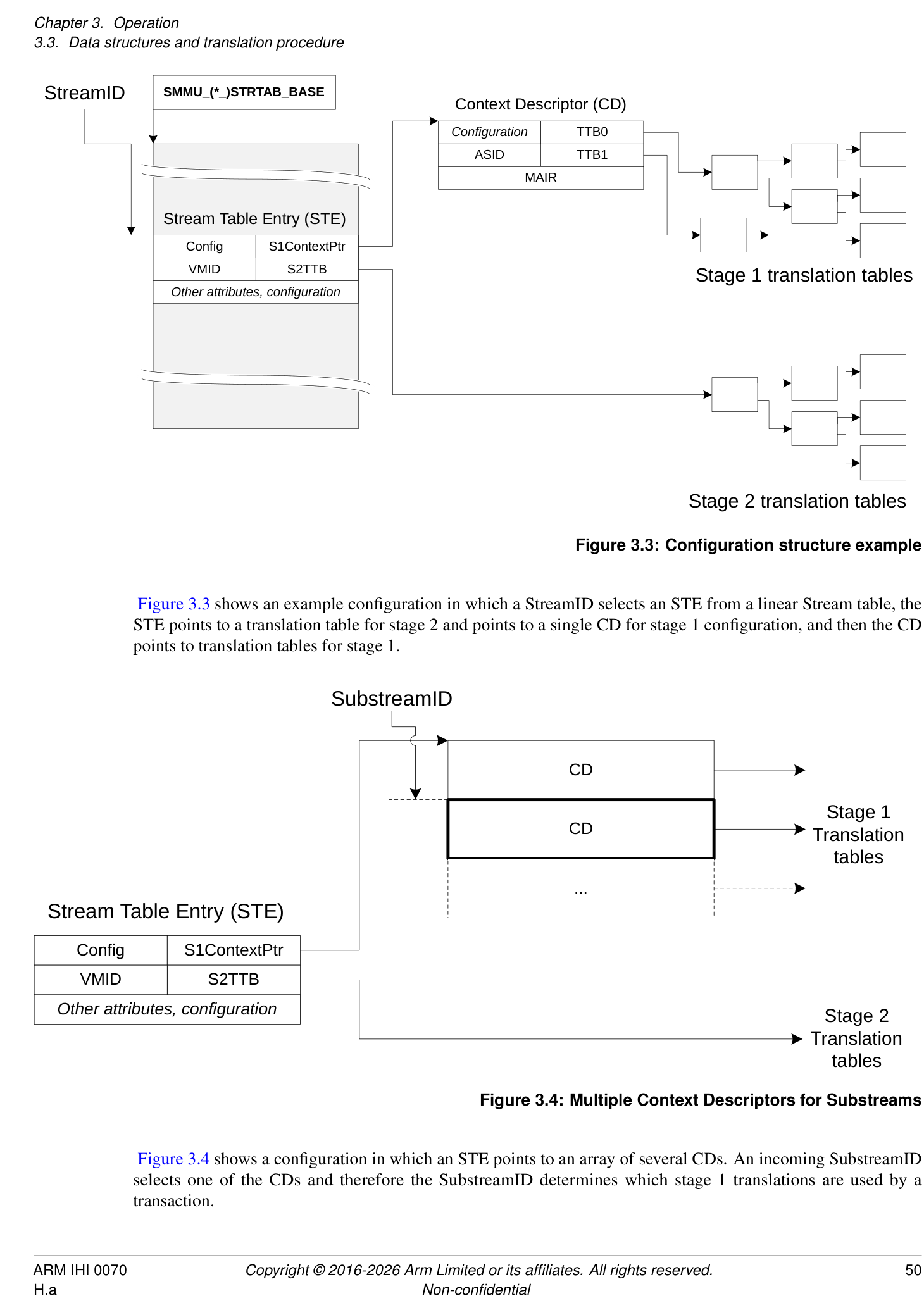
Figure 3.3 shows an example configuration in which a StreamID selects an STE from a linear Stream table, the STE points to a translation table for stage 2 and points to a single CD for stage 1 configuration, and then the CD points to translation tables for stage 1.
SubstreamID
CD
Stage 1
CD Translation
tables
...
Stream Table Entry (STE)
Config S1ContextPtr
VMID S2TTB
Other attributes, configuration
Stage 2
Translation
tables
Figure 3.4: Multiple Context Descriptors for Substreams

Figure 3.4 shows a configuration in which an STE points to an array of several CDs. An incoming SubstreamID selects one of the CDs and therefore the SubstreamID determines which stage 1 translations are used by a transaction.
SMMU_(_)STRTAB_BASE
Stage 1
STE CD Translation
STE tables
L1 ST ptr CD
L1 ST ptr
CD
CD
L1 CD ptr
STE L1 CD ptr
CD
Figure 3.5: Multi-level Stream and CD tables
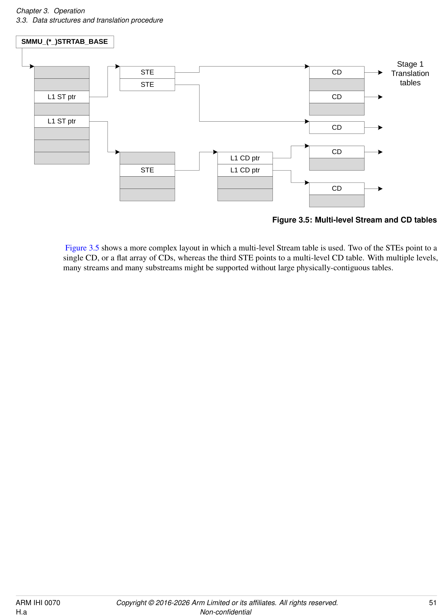
Figure 3.5 shows a more complex layout in which a multi-level Stream table is used. Two of the STEs point to a single CD, or a flat array of CDs, whereas the third STE points to a multi-level CD table. With multiple levels, many streams and many substreams might be supported without large physically-contiguous tables.
VA (BA)
Stage 1 translation
VA to IPA
IPA
Stage 2 translation
IPA to PA
PA
Bypass
Bypass
Figure 3.6: Translation stages and addresses
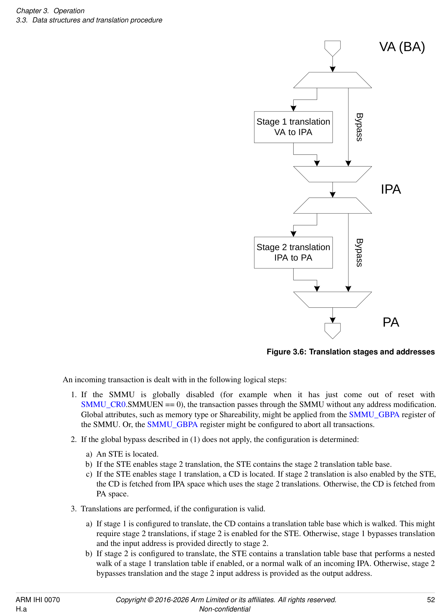
An incoming transaction is dealt with in the following logical steps:
-
If the SMMU is globally disabled (for example when it has just come out of reset with SMMU_CR0.SMMUEN == 0), the transaction passes through the SMMU without any address modification. Global attributes, such as memory type or Shareability, might be applied from the SMMU_GBPA register of the SMMU. Or, the SMMU_GBPA register might be configured to abort all transactions.
-
If the global bypass described in (1) does not apply, the configuration is determined:
-
a) An STE is located.
-
b) If the STE enables stage 2 translation, the STE contains the stage 2 translation table base.
-
c) If the STE enables stage 1 translation, a CD is located. If stage 2 translation is also enabled by the STE, the CD is fetched from IPA space which uses the stage 2 translations. Otherwise, the CD is fetched from PA space.
-
-
Translations are performed, if the configuration is valid.
-
a) If stage 1 is configured to translate, the CD contains a translation table base which is walked. This might require stage 2 translations, if stage 2 is enabled for the STE. Otherwise, stage 1 bypasses translation and the input address is provided directly to stage 2.
-
b) If stage 2 is configured to translate, the STE contains a translation table base that performs a nested walk of a stage 1 translation table if enabled, or a normal walk of an incoming IPA. Otherwise, stage 2 bypasses translation and the stage 2 input address is provided as the output address.
-
-
A transaction with a valid configuration that does not experience a fault on translation has the output address (and memory attributes, as appropriate) applied and is forwarded.
Note: This sequence illustrates the path of a transaction on a Non-secure stream. If Secure state is supported, the path of a transaction on a Secure stream is similar, except SMMU_S_CR0.SMMUEN and SMMU_S_GBPA control bypass.
An implementation might cache data as required for any of these steps. Section 16.2 Caching describes caching of configuration and translation structures.
Furthermore, events might occur at several stages in the process that prevent the transaction from progressing any further. If a transaction fails to locate valid configuration or is of an unsupported type, it is terminated with an abort, and an event might be recorded. If the transaction progresses as far as translation, faults can arise at either stage of translation. The configuration that is specific to the CD and STEs that are used determines whether the transaction is terminated or whether it is stalled, pending software fault resolution, see section 3.12 Fault models, recording and reporting .
The two translation stages are described using the VA to IPA and IPA to PA stages of the Armv8-A Virtualization terminology.
Note: Some systems refer to the SMMU input as a Bus Address (BA). The term VA emphasizes that the input address to the SMMU can potentially be from the same virtual address space as a PE process (using VAs).
Unless otherwise specified, translation tables and their configuration fields act exactly the same way as their equivalents specified in the Armv8-A Translation System for PEs [2].
If an SMMU does not implement one of the two stages of translation, it behaves as though that stage is configured to permanently bypass translation. Other restrictions are also relevant, for example it is not valid to configure a non-present stage to translate. An SMMU must support at least one stage of translation.
3.3.3 Configuration and Translation lookup
Get Context
SubstreamID ASID, translation table
Descriptor Miss Walk
TLB
translation
{Security, Fill tables
StreamID StreamWorld (translation regime) StreamWorld,
VMID,
Get Stream  ASID,
Table Entry Address}
VMID, Stage 2 translation table to
{PA,
Permissions}
Input address Output address (PA)
Configuration lookup Translation lookup
Data
Input transaction
Output transaction
Figure 3.7: Configuration and translation lookup sequence
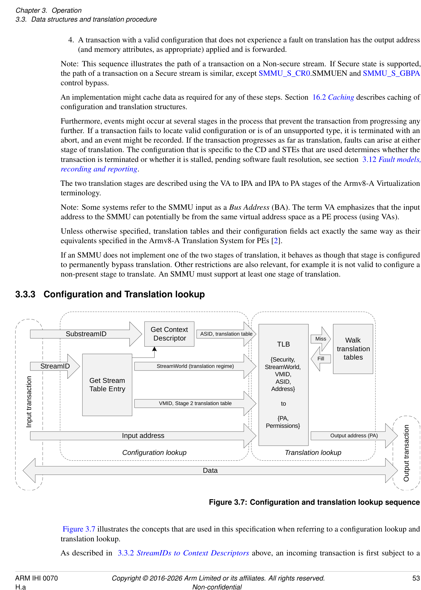
Figure 3.7 illustrates the concepts that are used in this specification when referring to a configuration lookup and translation lookup.
As described in 3.3.2 StreamIDs to Context Descriptors above, an incoming transaction is first subject to a
configuration lookup, and the SMMU determines how to begin to translate the transaction. This involves locating the appropriate STE then, if required, a CD.
The configuration lookup stage does not depend on the input address and is a function of the:
-
SMMU global register configuration.
-
Incoming transaction StreamID.
-
Incoming transaction SubstreamID (if supplied).
The result of the configuration lookup is the stream or substream-specific configuration that locates the translation, including:
-
Stage 1 translation table base pointers, ASID, and properties modifying the interpretation or walk of the translation tables (such as translation granule).
-
Stage 2 translation table base pointer, VMID and properties modifying the interpretation or walk of the translation table.
-
Stream-specific properties, such as the StreamWorld (the Exception Level, or translation regime, in PE terms) to which the stream is assigned.
The translation lookup stage logically works the same way as a PE memory address translation system. The output is the final physical address provided to the system, which is a function of the:
-
Input address
-
StreamWorld (Stream Security state and Exception level), ASID and VMID (which are provided from the previous step).
Figure 3.7 shows a PE-style TLB used in the translation lookup step. Arm expects the SMMU to use a TLB to cache translations instead of performing translation table walks for each transaction, but this is not mandatory.
Note: For clarity, Figure 3.7 does not show error reporting paths or CD fetch through stage 2 translation (which would also access the TLB or translation table walk facilities). An implementation might choose to flatten or combine some of the steps shown, while maintaining the same behavior.
A cached translation is associated with a StreamWorld that denotes its translation regime. StreamWorld is directly equivalent to an Exception level on a PE.
The StreamWorld of a translation is determined by the configuration that inserts that translation. The StreamWorld of a cached translation is determined from the combination of the Security state of an STE, its STE.Config field, its STE.STRW field, and the corresponding SMMU_(*_)CR2.E2H configuration. See the STE.STRW field in section 5.2 Stream Table Entry.
In addition to insertion into a TLB, the StreamWorld affects TLB lookups, and the scope of different types of TLB invalidations. An SMMU implementation is not required to distinguish between cached translations inserted for EL2 versus EL2-E2H.
For the behavior of TLB invalidations, see section 3.17 TLB tagging, VMIDs, ASIDs and participation in broadcast TLB maintenance .
A translation is associated with one of the following StreamWorlds:
| StreamWorld | Properties equivalent to |
|---|---|
| NS-EL1 | Non-secure EL1&0 |
| NS-EL2 | Non-secure EL2. This is when E2H is not used, and translations do not have an ASID tag. |
| NS-EL2-E2H | Non-secure EL2&0. This is when E2H is used, and translations have an ASID tag. |
| S-EL2 | Secure EL2. This is when E2H is not used, and translations do not have an ASID tag. |
| S-EL2-E2H | Secure EL2&0. This is when E2H is used, and translations have an ASID tag. |
| Secure | Either: |
| StreamWorld | Properties equivalent to |
|---|---|
| - The single translation regime that is used by Secure EL1 and Secure EL3 when EL3 is running in | |
| AArch32 state. | |
| - Secure EL1&0 when EL3 is running in AArch64 state. EL3 has a separate translation regime. | |
| This regime has an ASID and, if Secure stage 2 is supported, a VMID. | |
| EL3 | EL3 when EL3 is running in AArch64 state and FEAT_RME is not implemented. |
| Realm-EL1 | Realm EL1&0. |
| Realm-EL2 | Realm EL2. This is when E2H is not used, and translations do not have an ASID tag. |
| Realm-EL2-E2H | Realm EL2&0. This is when E2H is used, and translations have an ASID tag. |
Note: StreamWorld can differentiate multiple translation regimes in the SMMU that are associated with different bodies of software at different Exception levels. For example, a Secure Monitor EL3 translation for address 0x1000 is different to (and unaffected by) a Non-secure hypervisor EL2 translation for address 0x1000, as are NS-EL1 translations for address 0x1000. Arm expects that the StreamWorld configured for a stream in the SMMU will match the Exception level of the software that controls the stream or device.
The term any-EL2 is used to describe behaviors common to NS-EL2, S-EL2, and Realm-EL2.
The term any-EL2-E2H is used to describe behaviors common to NS-EL2-E2H, S-EL2-E2H, and Realm-EL2-E2H StreamWorlds.
In the same way as in an Armv8-A MMU, a translation is architecturally unique if it is identified by a unique set of {StreamWorld, VMID, ASID, Address} input parameters.
For example, the following are unique and can all co-exist in a TLB:
-
Entries with the same address, but different ASIDs.
-
Entries with the same address and ASID, but different VMIDs.
-
Entries with the same address and ASID but a different StreamWorld.
Architecturally, a translation is not uniquely identified by a StreamID and SubstreamID. This results in two properties:
-
A translation is not required to be unique for a set of transaction input parameters (StreamID, SubstreamID). – Two streams can be configured to use the same translation configuration and the resulting ASID/VMID from their configuration lookup will identify a single set of shared TLB entries.
-
Multiple StreamID/SubstreamID configurations that result in identical ASID/VMID/StreamWorld configuration must maintain the same configuration where configuration can affect TLB lookup.
- For example, two streams configured for a stage 1, NS-EL1 with ASID == 3 must both use the same translation table base addresses and translation granule.
When translating an address, any-EL2 and EL3 regimes use only one translation table. CD.TTB1 is unused in these configurations. All other StreamWorlds use both translation tables, and therefore CD.TTB0 and CD.TTB1 are both required.
Only some stage 1 translation table formats are valid in each StreamWorld, consistent with the PE. Valid combinations are described in the CD.AA64 description. Selecting an inconsistent combination of StreamWorld and CD.AA64 (for example, using VMSAv8-32 LPAE translation tables to represent a VMSAv8-64 EL3 translation regime) causes the CD to be ILLEGAL.
Secure stage 1 permits VMSAv8-32 LPAE, VMSAv8-64 and VMSAv9-128 translation tables. Secure stage 2 is not supported for VMSAv8-32 LPAE translation tables.
In this specification, the term TLB is used to mean the concept of a translation cache, indexed by StreamWorld/VMID/ASID and VA.
SMMU cache maintenance commands therefore fall into two groups:
-
Configuration cache maintenance, acting upon StreamIDs and SubstreamIDs.
-
TLB maintenance, acting on addresses, ASIDs, VMIDs and StreamWorld.
The second set of commands directly matches broadcast TLB maintenance operations that might be available from PEs in some systems. The StreamWorld tag determines how TLB entries respond to incoming broadcast TLB invalidations and TLB invalidation SMMU commands, see section 3.17 TLB tagging, VMIDs, ASIDs and participation in broadcast TLB maintenance for details.
3.3.4 Transaction attributes: incoming, two-stage translation and overrides
In addition to an address, size and read/write attributes, an incoming transaction might be presented to the SMMU with other attributes, such as an access type (for example Device, WB-cached Normal memory), Shareability (for example Outer Shareable), cache allocation hints, and permissions-related attributes, instruction/data, privileged/unprivileged, Secure/Non-secure. Some of these attributes are used to check the access against the page permissions that are determined from the translation tables. After passing through the SMMU, a transaction presented to the system might also have a set of attributes, which might have been affected by the SMMU.
Depending on the StreamWorld configuration, these attributes can be configured differently. For example, the format of access permissions in a stage 1 translation table descriptor is affected when located from a configuration with StreamWorld == any-EL2 or StreamWorld == EL3, consistent with the Armv8 Translation System [2]. Specifically, the AP[1] bit (of the AP[2:1] field) is ignored and treated as if it were 1 because privilege checks are ignored for EL2 and EL3 (VMSAv8-64 and VMSAv9-128) translations. However, any-EL2-E2H translations maintain privileged/non-privileged checks in the same manner as EL1.
The details of how input attributes affect the attributes output into the system, in combination with translation table attributes and other configuration, is described in detail in Chapter 13 Attribute Transformation .
The input attributes are conceptually provided from the system, either conveyed from a client device that defines the transaction attributes in a device-specific way, or set in a system-specific way by the interconnect before the transaction is input to the SMMU.
As an overview:
- Permission-related attributes (instruction/data, privileged/unprivileged) and read/write properties are used for checking against translation table permissions, which might deny the access. The permission-related attributes input into the SMMU might be overridden on a per-device basis before the permission checks are performed, using the INSTCFG, PRIVCFG, and NSCFG STE fields. See section 13.5 Summary of attribute/permission configuration fields for information about output attributes.
Note: The overrides might be useful if a device is not able to express a particular kind of traffic.
- Other attributes (memory type, Shareability, cache hints) are intended to have an effect on the memory system rather than the SMMU, for example, control cache lookup for the transaction. The attributes output into the memory system are a function of the attributes specified by the translation table descriptors (at stage 1, stage 2, or stage 1 and stage 2) used to translate the input address. The SMMU might convey attributes input from a device through this process, so that the device might influence the final transaction access, and input attributes might be overridden on a per-device basis using the MTCFG/MemAttr, SHCFG, ALLOCCFG STE fields. The input attribute, modified by these fields, is primarily useful for setting the resulting output access attribute when both stage 1 and stage 2 translation is bypassed (no translation table descriptors to determine attribute) but can also be useful for stage 2-only configurations in which a device stream might have finer knowledge about the required access behavior than the general virtual machine-global stage 2 translation tables.
The STE attribute and permission override fields, MTCFG/MemAttr, SHCFG, ALLOCCFG, INSTCFG, PRIVCFG, and NSCFG, allow an incoming value to be used or, for each field, a specific override value to be selected. For example, INSTCFG can configure a stream as Always Data, replacing an incoming INST property that might be in either state. However, in SMMU implementations that are closely-coupled to, or embedded in, a device, the incoming attribute can always be considered to be the most appropriate. When an SMMU and device guarantee
that the incoming attributes are correct, it is permissible for an SMMU to always use the incoming value for each attribute value. See SMMU_IDR1.ATTR_TYPES_OVR and SMMU_IDR1.ATTR_PERMS_OVR for more information. For an SMMU that cannot guarantee that these attributes are always provided correctly from the client device, for example a discrete SMMU design, Arm strongly recommends supporting overrides of incoming attributes.
3.3.5 Translation table descriptors
The A-profile architecture[2] defines bits [63:60] of stage 2 Block and Page descriptors as being Reserved for use by a System MMU. In SMMUv3.1 and later, these bits are Reserved, RES0.
Note: When PBHA is enabled for a bit in this range, bits [62:60] are affected by the PBHA mechanism. When PBHA is not enabled, the previous definition applies.
3.4 Address sizes
There are three address size concepts to consider in the SMMU, the input address size from the system, the Intermediate Address Size (IAS), and the Output Address Size (OAS):
-
The SMMU input address size is 64 bits.
- Note: See section 3.4.1 Input address size and Virtual Address size for recommendations on how a smaller interconnect or device address capability is presented to the SMMU.
-
IAS reflects the maximum usable IPA of an implementation that is generated by stage 1 and input to stage 2:
-
This term is defined to illustrate the handling of intermediate addresses in this section and is not a configurable parameter.
-
The maximum usable IPA size of an SMMU is defined in terms of other SMMU implementation choices, as:
-
IAS = MAX((SMMU_IDR0.TTF[0]==1 ? 40 : 0), (SMMU_IDR0.TTF[1]==1 ? OAS : 0));
-
VMSAv8-32 LPAE always supports an IPA size of 40 bits, whereas VMSAv8-64 and VMSAv9-128 limits the maximum IPA size to the maximum PA size. Otherwise, when VMSAv8-32 LPAE is not implemented, the IPA size equals OAS, the PA size, and might be smaller than 40 bits.
-
The purpose of definition of the IAS term is to abstract away from these implementation variables.
-
OAS reflects the maximum usable PA output from the last stage of VMSAv8-64 or VMSAv9-128 translations, and must match the system physical address size. The OAS is discoverable from SMMU_IDR5.OAS. Final-stage VMSAv8-32 LPAE translations always output 40 bits which are zero-extended into a larger OAS, or truncated to a smaller OAS.
Note: Except where explicitly noted, all address translation and fault checking behavior is consistent with Armv8-A [2].
If the SMMU is disabled (with SMMU_()CR0.SMMUEN == 0, and SMMU()GBPA.ABORT == 0 allows traffic bypass), the input address is presented directly to the output PA. If the input address of a transaction exceeds the size of the OAS, the transaction is terminated with an abort and no event is recorded. Otherwise, when SMMU(*_)CR0.SMMUEN == 1, transactions are treated as described in the rest of this section.
When a stream selects an STE with STE.Config == 0b100, transactions bypass all stages of translation. If the input address of a transaction exceeds the size of the OAS, the transaction is terminated with an abort and a stage 1 Address Size fault (F_ADDR_SIZE) is recorded.
Note: In Armv8-A PEs, when both stages of translation bypass, a (stage 1) Address Size fault might be generated where an (input) address is greater than the PA size, depending on whether a PE is in AArch32 or AArch64 state. This behavior does not directly translate to the SMMU because no configuration is available to select translation system when in bypass or disabled, therefore the address size is always tested.
When a stream selects an STE with one or more stages of translation present:
For input to stage 1, the input address is treated as a VA (see section 3.4.1 Input address size and Virtual Address size ) and if stage 1 is not bypassed the following stage 1 address checks are performed:
-
On input, a stage 1 Translation fault (F_TRANSLATION) occurs if the VA is outside the range specified by the relevant CD:
- a. For a CD configured as VMSAv8-32 LPAE, the maximum input range is fixed at 32 bits, and the range of the address input into a given TTB0 or TTB1 translation table is determined by the T0SZ and T1SZ fields.
Note: The arrangement of the TTB0/TTB1 translation table input spans might be such that there is a range of 32-bit addresses that is outside both of the TTB0 and TTB1 spans and will always cause a Translation fault.
-
b. For a CD configured as VMSAv8-64, the range is determined by the T0SZ and T1SZ fields.
-
i. For SMMUv3.0, up to a maximum of 49 bits (two 48-bit TTB0/TTB1).
-
ii. For SMMUv3.1 and later, then for each TTBx, the maximum input size is:
-
48 bits, if any of the following are true:
-
SMMU_IDR5.VAX == 0b00.
-
The TTBx is configured for a 4KB or 16KB granule using CD.TGx and CD.DS == 0.
-
52 bits, if SMMU_IDR5.VAX == 0b01 or 0b10 and one of the following is true:
-
The TTBx is configured for a 64KB granule using CD.TGx.
-
CD.DS == 1 and the TTBx is configured for a 4KB or 16KB granule using CD.TGx.
-
-
c. For a CD configured as VMSAv9-128, the range is determined by the T0SZ and T1SZ fields. For each TTBx, the maximum input size is:
-
48 bits, if SMMU_IDR5.VAX == 0b00.
-
52 bits, if SMMU_IDR5.VAX == 0b01.
-
55 bits for EL1 and EL2-E2H, if SMMU_IDR5.VAX == 0b10.
-
56 bits for EL3, if SMMU_IDR5.VAX == 0b10.
-
A VA is inside the range only if it is correctly sign-extended from the top bit of the range size upwards, although an exception is made for Top Byte Ignore (TBI) configurations.
Note: For example, with a 49-bit VA range and TBI disabled, addresses 0x0000FFFFFFFFFFFF and 0xFFFF000000000000 are within the range but 0x0001000000000000 and 0xFFFE000000000000 are not. See 3.4.1 Input address size and Virtual Address size below for details.
-
The address output from the translation causes a stage 1 Address Size fault if it exceeds the range of the effective IPA size for the given CD:
- a. For VMSAv8-32 LPAE CDs, the IPA size is fixed at 40 bits (the IPS field of the CD is IGNORED). b. For VMSAv8-64 and VMSAv9-128 CDs, the IPA size is given by the effective value of the IPS field of the CD, which is capped to the OAS.
If bypassing stage 1 (because STE.Config == 0b1x0, STE.S1DSS == 0b01 or if unimplemented), the input address is passed directly to stage 2 as the IPA. If the input address of a transaction exceeds the size of the IAS, a stage 1 Address Size fault occurs, the transaction is terminated with an abort and F_ADDR_SIZE is recorded. Otherwise, the address might still lie outside the range that stage 2 will accept. In this case, the stage 2 check 1 described in this section causes a stage 2 Translation fault.
Note: The TBI configuration can only be enabled when a CD is used (that is when stage 1 translates) and is always disabled when stage 1 is bypassed or disabled.
Note: The SMMU stage 1 bypass behavior is analogous to a PE with stage 1 disabled but stage 2 translating. The SMMU checks stage 1 bypassed addresses against the IAS, which (when VMSAv8-32 LPAE support is implemented) might be greater than the PA. This supports stage 2-only assignment of devices to guest VMs expecting to program 40-bit DMA addresses, which are input to stage 2 translation.
Note: This also means that an SMMU implementing only stage 2, or implementing both stages but translating through stage 2 only, can still produce a fault marked as coming from stage 1.
Stage 2 receives an IPA, and if not bypassing, the following stage 2 address size checks are performed:
-
On input, a stage 2 Translation fault occurs if the IPA is outside the range configured by the relevant S2T0SZ field of the STE.
-
a. For an STE configured as VMSAv8-32 LPAE (see STE.S2AA64), the input range is capped at 40 bits (and cannot exceed 40 bits regardless of the IAS size.)
-
b. For an STE configured as VMSAv8-64 or VMSAv9-128, the input range is capped to the IAS.
-
Note: If the SMMU supports VMSAv8-32 the IAS is at least 40 bits (that is, even if OAS < 40). This ensures, for a system having OAS < 40, that a VMSAv8-64 stage 2 can accept a 40-bit IPA from a VMSAv8-32 LPAE stage 1.
- c. For SMMUv3.1 and later, when IAS is 52 bits or 56 bits, then for an STE configured as VMSAv8-64 the stage 2 input range is limited to 52 bits and is further limited to 48 bits unless STE.S2TG indicates 64KB granule or STE.S2DS == 1.
-
The address output from the translation causes a stage 2 Address Size fault if it exceeds the effective PA output range:
-
a. For a VMSAv8-64 or VMSAv9-128 STE, this is the effective value configured in the S2PS field of the STE (which is capped to the OAS). Note: For information on the permitted effective output address sizes, see STE.S2PS.
-
b. For a VMSAv8-32 LPAE STE, this output range is fixed at 40 bits and the STE.S2PS field is IGNORED. If the OAS is less than 40, and if the output address is outside the range of the OAS, the address is silently truncated to fit the OAS.
-
After this check, if the output address of stage 2 is smaller than the OAS, the address is zero-extended to match the OAS.
If bypassing stage 2 (because STE.Config == 0b10x or if unimplemented), the IPA is presented directly as the PA output address. If the IPA is outside the range of the OAS, the address is silently truncated to fit the OAS. If the IPA is smaller than the OAS, it is zero-extended.
Note: Because the SMMU contains configuration structures that are checked for validity before beginning translation table walks, certain configuration errors are detected as an invalid structure configuration. This includes STE.S2TTB being out of range of the effective stage 2 output address size, or CD.TTBx being out of range of the effective stage 1 output address size. These invoke C_BAD_STE or C_BAD_CD configuration faults, respectively, instead of an Address Size fault.
3.4.1 Input address size and Virtual Address size
The architectural input address size of the SMMU is 64 bits. If a client device outputs an address smaller than 64 bits, or if the interconnect between a client device and the SMMU input supports fewer than 64 bits of address, the smaller address is converted to a 64-bit SMMU input address in a system-specific manner. This conversion is outside of the scope of this specification, but must comply with the rules in this section.
The A-profile architecture provides support for different maximum VA size, as follows:
-
Armv8.0 and Armv8.1 [2] support a maximum of a 49-bit VA in AArch64 state, meaning there are up to 49 significant lower bits that are sign-extended to a 64-bit address.
-
Armv8.2 to Armv8.8 [2] supports a maximum of a 53-bit VA or 49-bit VA in AArch64 state, meaning there are up to 53 or 49 significant lower bits that are sign-extended to a 64-bit address.
-
Armv8.9 [2] supports a maximum of a 56-bit VA, 53-bit VA or 49-bit VA in AArch64 state, meaning there are up to 56, 53 or 49 significant lower bits respectively, that are sign-extended to a 64-bit address. A 56-bit VA is supported for VMSAv9-128 translations.
Stage 1 translation contexts configured as VMSAv8-64 or VMSAv9-128 have an input VA range that is configurable up to the maximum supported size as described above (arranged as two halves and translated through TTB0 and TTB1).
The term, VAS, represents the VA size chosen for a given SMMU implementation, determined as follows:
-
When SMMU_IDR5.VAX == 0b00, this is 49 bits (2 × 48 bits).
-
When SMMU_IDR5.VAX == 0b01, this is 53 bits (2 × 52 bits).
-
When SMMU_IDR5.VAX == 0b10, this is 56 bits (2 × 55 bits for EL1 and EL2-E2H StreamWorlds, or 1 × 56 bits for EL3 StreamWorld).
Note: In SMMUv3.0, SMMU_IDR5.VAX is RES0 and therefore VAS is always 49 bits.
Stage 1’s high translation table, TTB1, can only be selected if VAS significant bits of address are presented to the SMMU sign-extended. If applications require use of both TTB0 and TTB1 then the system design must transmit addresses of at least VAS bits end-to-end, from device address registers through the interconnect to the SMMU, and that sign-extension occurs from the input MSB upwards as described in this section.
Stage 1 translation contexts configured as VMSAv8-32 LPAE have a 32-bit VA. In this case, bits [31:0] of the input address are used directly as the VA. A Translation fault is raised if the upper 32 bits of the input address are not all zero. The TxSZ fields are used to select TTB0 or TTB1 from the upper bits [31:n] in the input range.
Input range checks made for a stage 1 VMSAv8-64 or VMSAv9-128 translation table configured (with TxSZ) for an input range of N significant bits fail unless bits VA[ AddrTop :N - 1] are identical.
-
When Top Byte Ignore (TBI) is not enabled, AddrTop == 63.
-
When TBI is enabled, AddrTop == 55, which means that VA[63:56] are ignored.
When TBI is enabled, only VA[55:N-1] must be identical and the effective VA[63:56] bits are taken to be a sign-extension of VA[55] for translation purposes.
Note: TBI configuration is part of the CD, so it can only be enabled when stage 1 translates. When stage 1 is bypassed or disabled, no CD is used and TBI is always disabled.
The term Upstream Address Size (UAS) represents the number of effective bits of address presented to the SMMU from a client device:
-
If 57 <= UAS < 64, TBI has meaning as there are bits supplied in VA[63:56] that might differ from VA[55:(VAS-1)]. TBI determines whether a Translation fault is invoked if they differ.
-
If VAS <= UAS < 57, TBI is meaningless as the input sign-extension means VA[63:56] cannot differ from VA[55].
-
If UAS <= VAS, the range checks can only fail if translation table range is configured with a T0SZ, or T1SZ, if UAS == 49, smaller than the presented address. That is, the maximum configuration of stage 1 translation tables covers any presented input address.
For VMSAv8-64 and VMSAv9-128, the stage 1 translation table, TTB0 or TTB1, is selected based on VA[55]. Therefore, because an address size from the client device that is less than the VAS bits is zero-extended to 64, this means VA[55] == 0 and TTB1 is never selected.
If any upper address bits of a 64-bit address programmed into a peripheral are not available to the SMMU sign-checking logic, whether by truncation in the interconnect or peripheral, software must not rely on mis-programmed upper bits to cause a Translation fault in the SMMU. If such checking is required within such a system, software must check the validity of upper bits of DMA addresses programmed into such a device.
All input address bits are recorded unmodified in SMMU fault event records.
3.4.2 Address alignment checks
The SMMU architecture does not check the alignment of incoming transaction addresses.
Note: For a PE, the alignment check is based on the size of an access. This semantic is not directly applicable to client device accesses.
3.4.3 Address sizes of SMMU-originated accesses
Distinct from client device accesses forwarded into the system, the SMMU originates accesses to the system for the purposes of:
-
Configuration structure access (STE, CD).
-
Queue access (Command, Event, PRI).
-
MSI interrupt writes.
-
Last-stage translation table walks:
- Note: Addresses output from stage 1 walks in a nested configuration are input to stage 2 and translated in the expected manner (including causing stage 1 Address Size faults, or stage 2 Translation faults from IPAs outside the stage 2 translation range), rather than being output into the system directly.
An access address can be out of range if it relates to a base address that is already greater than an allowed address size, or if an index is applied to a base address so that the result is greater than an allowed address size. If an
access address is calculated to be a PA value greater than the SMMU OAS or physical address size, or an IPA value greater than the IAS or intermediate address size, behavior is as follows:
| Access type | Confgured by | Address type Behavior when address too large |
|---|---|---|
| CD fetch or L1CD fetch | STE.S1ContextPtr | If stage 1-only, PA Truncate to OAS or F_CD_FETCH or C_BAD_STE(1) |
| If stage 2 present, IPA Truncate to IAS or C_BAD_STE or Stage 2 Translation fault (2) | ||
| CD fetch | L1CD.L2Ptr | If stage 1-only, PA Truncate to OAS or F_CD_FETCH or C_BAD_SUBSTREAMID(3) |
| If stage 2 present, IPA Truncate to IAS or C_BAD_SUBSTREAMID or stage 2 Translation fault (4) | ||
| STE fetch | SMMU_(*_)STRTAB_BASE or L1STD.L2Ptr | PA Truncate to OAS or F_STE_FETCH (5) |
| VMS fetch | STE.VMSPtr | PA C_BAD_STE |
| Queue access | SMMU_(*_)*Q_BASE | PA/IPA(1) Truncate to OAS (6) |
| MSI write | SMMU_(_)_IRQ_CFG {0,1,2} or CMD_SYNCarguments | PA Truncate to OAS (6) |
| Last-stage translation table walk | Addresses derived from intermediate translation table descriptors located usingSTE.S2TTBorSTE.S_S2TTB orCD.TTB{0,1}, after the frst level translation table descriptor fetch. | PA Stage 1/2 Address Size fault |
| Starting-level translation table descriptor address inSTE.S2TTBor STE.S_S2TTBorCD.TTB{0,1} | PA CD or STE ILLEGAL (see CD.TTB{0,1} andSTE.S2TTB description). |
- (1) The base address in SMMU_DCMDQ_BASEn.ADDR undergoes translation in the SMMU. See section 3.5.7.3 DCMDQ qSID and STE Association .
In the context of these respective access types:
-
An implementation of SMMUv3.1 or later generates C_BAD_STE and terminates the transaction. It is CONSTRAINED UNPREDICTABLE whether an SMMUv3.0 implementation:
-
a. Generates an F_CD_FETCH and terminates the transaction. The event contains the non-truncated fetch address.
-
b. Generates a C_BAD_STE and terminates the transaction.
-
c. Truncates STE.S1ContextPtr to the OAS and initiates a read of a CD/L1CD from this address (translation continues).
-
-
It is CONSTRAINED UNPREDICTABLE whether an implementation:
-
a. Generates a C_BAD_STE and terminates the transaction.
-
b. Inputs the IPA to stage 2 without truncation, generating a stage 2 Translation fault that reports a non-truncated fault address.
-
c. SMMUv3.0 only, inputs the IPA to stage 2 with truncation to the IAS. If translation is successful, initiates a read of a CD/L1CD from the result otherwise generates a stage 2 fault that reports a truncated fault address.
-
-
An implementation of SMMUv3.1 or later generates C_BAD_SUBSTREAMID and terminates the transaction. It is CONSTRAINED UNPREDICTABLE whether an SMMUv3.0 implementation:
-
a. Generates an F_CD_FETCH and terminates the transaction. The event contains the non-truncated fetch address.
-
b. Generates a C_BAD_SUBSTREAMID and terminates the transaction.
-
c. Truncates L1CD.L2Ptr to the OAS and initiates a read of a CD from this address (translation continues).
-
-
It is CONSTRAINED UNPREDICTABLE whether an implementation:
-
a. Generates a C_BAD_SUBSTREAMID and terminates the transaction.
-
b. Inputs the IPA to stage 2 without truncation, generating a stage 2 Translation fault that reports a non-truncated fault address.
-
c. SMMUv3.0 only, inputs the IPA to stage 2 with truncation to the IAS. If translation is successful, initiates a read of a CD from the result otherwise generates a stage 2 fault that reports a truncated fault address.
-
-
It is CONSTRAINED UNPREDICTABLE whether an implementation truncates an STE fetch address (and continues translation) or generates an F_STE_FETCH condition which terminates the transaction and might deliver an error event.
-
Note: When hypervisor software presents an emulated SMMU interface to a guest, Arm recommends that guest-provided addresses are correctly masked to the IPA size to ensure consistent SMMU behavior from the perspective of the guest driver.
In all cases where a non-truncated address is reported in a fault (for instance, a stage 2 Translation fault), the reported address is the calculated address of the structure being accessed, for example an L1CD address calculated from a base address of STE.S1ContextPtr indexed by the incoming SubstreamID to locate a L1CD structure.
The address of an L1CD or CD, given by STE.S1ContextPtr or L1CD.L2Ptr, is not subject to a stage 1 Address Size fault check.
In summary, configuration registers, command fields, and structure fields programmed with out-of-range physical addresses might truncate the addresses to the OAS or PA size.
Note: This behavior in part arises from the fact that register address fields are not required to provide storage for high-order physical address bits beyond the OAS. See section 6.3 Register formats for details.
Note: Commands, register, and structure fields taking IPA addresses store the entire field width so that a potential stage 2 fault can be correctly raised (providing a full non-truncated IPA in a fault record).
3.5 Command and Event queues
All SMMU queues for both input to, and output from the SMMU are arranged as circular buffers in memory. A programming interface has one Command queue for input and one Event queue (and optionally one PRI queue) for output. Each queue is used in a producer-consumer fashion so that an output queue contains data produced by the SMMU and consumed by software. An input queue contains data produced by software, consumed by the SMMU.
3.5.1 SMMU circular queues
A queue is arranged as a 2[n] -items sized circular FIFO with a base pointer and two index registers, PROD and CONS, indicating the producer and consumer current positions in the queue. In each of the output and input roles, only one index is maintained by the SMMU, with the other is maintained by software.
For an input queue (Command queue), the PROD index is updated by software after inserting an item into the queue, and is read by the SMMU to determine new items. The CONS index is updated by the SMMU as items are consumed, and is read by software to determine that items are consumed and space is free. An output queue is the exact opposite.
PROD indicates the index of the location that can be written next, if the queue is not full, by the producer. CONS indicates the index of the location that can be read next, if the queue is not empty. The indexes must always increment and wrap to the bottom when they pass the top entry of the queue.
The queues use the mirrored circular buffer arrangement that allows all entries to be valid simultaneously (rather than N-1 valid entries in other circular buffer schemes). Each index has a wrap flag, represented by the next higher bit adjacent to the index value contained in PROD and CONS. This bit must toggle each time the index wraps off the high-end and back onto the low-end of the buffer. It is the responsibility of the owner of each index, producer or consumer, to toggle this bit when the owner updates the index after wrapping. It is intended that software reads the register, increments or wraps the index (toggling wrap when required), and writes back both wrap and index fields at the same time. This single update prevents inconsistency between index and wrap state.
-
If the two indexes are equal and their wrap bits are equal, the queue is empty and nothing can be consumed from it.
-
If the two indexes are equal and their wrap bits are different, the queue is full and nothing can be produced to it.
-
If the two indexes differ or the wrap bits differ, the consumer consumes entries, incrementing the CONS index until the queue is empty (both indices and wrap bits are equal).
Therefore, the wrap bits differentiate the cases of an empty buffer and a full buffer where otherwise both indexes would indicate the same location in both full and empty cases.
On initialization, the queue indexes are written by the agent controlling the SMMU before enabling the queue. The queue indexes must be initialized into one of the following consistent states:
-
PROD.WR == CONS.RD and PROD.WR_WRAP == CONS.RD_WRAP, representing an empty queue. – Note: Arm expects this to be the state on normal initialization.
-
PROD.WR == CONS.RD and PROD.WR_WRAP != CONS.RD_WRAP, representing a full queue.
-
PROD.WR > CONS.RD and PROD.WR_WRAP == CONS.RD_WRAP, representing a partially-full queue.
-
PROD.WR < CONS.RD and PROD.WR_WRAP != CONS.RD_WRAP, representing a partially-full queue.
The agent controlling the SMMU must not write queue indexes to any of the following inconsistent states whether at initialization or after the queue is enabled:
-
PROD.WR > CONS.RD and PROD.WR_WRAP != CONS.RD_WRAP
-
PROD.WR < CONS.RD and PROD.WR_WRAP == CONS.RD_WRAP
If the queue indexes are written to an inconsistent state, one of the following CONSTRAINED UNPREDICTABLE behaviors is permitted:
-
The SMMU consumes, or produces as appropriate to the given queue, queue entries at UNKNOWN locations in the queue.
-
The SMMU does not consume, or produce as appropriate, queue entries while the queue indexes are in an inconsistent state.
-
For a queue where the SMMU is the producer, the SMMU treats the queue as though it is full while the queue indexes are in an inconsistent state.
Each circular buffer is 2[n] -items in size, where 0 <= n <= 19. An implementation might support fewer than 19 bits of index. Each PROD and CONS register is 20 bits to accommodate the maximum 19-bit index plus the wrap bit. The actual buffer size is determined by software, up to the discoverable SMMU IMPLEMENTATION DEFINED limit. The position of the wrap bit depends on the configured index size.
Note: For example, when a queue is configured with 128 entries it means:
-
The queue indices are 7-bit.
-
PROD.WR and CONS.RD fields are 7 bits large. The queue indexes are bits [6:0] of PROD and CONS.
-
The wrap bit [7] of PROD and CONS registers. Bits [19:8] are ignored.
The lifecycle of a circular buffer is shown in Figure 3.8.
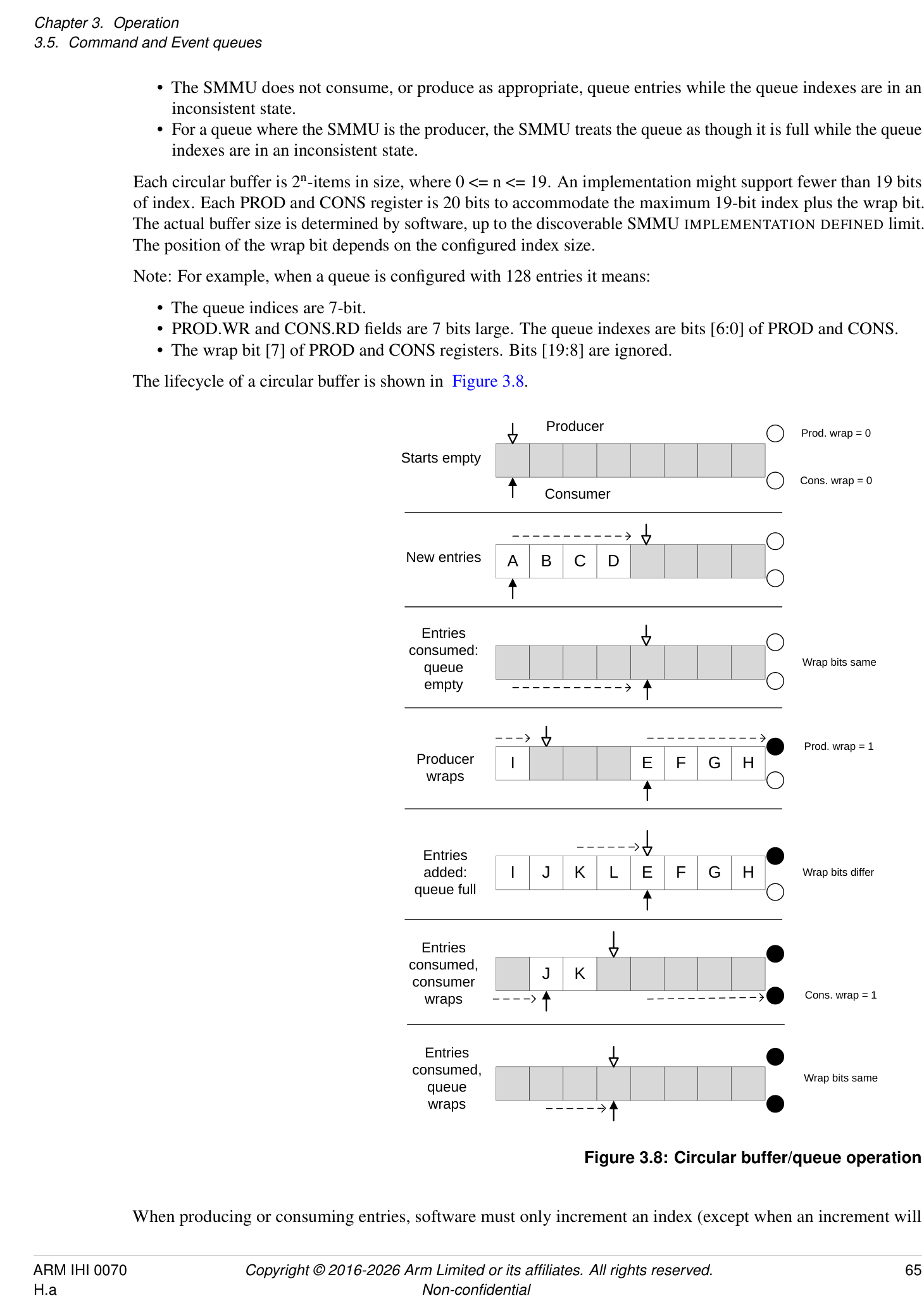
Producer
Prod. wrap = 0
Starts empty
Cons. wrap = 0
Consumer
New entries A B C D
Entries
consumed:
Wrap bits same
queue
empty
Prod. wrap = 1
Producer  I E F G H
wraps
Entries
added:  I J K L E F G H Wrap bits differ
queue full
Entries
consumed,
J K
consumer
wraps Cons. wrap = 1
Entries
consumed,
Wrap bits same
queue
wraps
Figure 3.8: Circular buffer/queue operation
When producing or consuming entries, software must only increment an index (except when an increment will
cause a wrap to the start). The index must never otherwise be moved backwards. The SMMU makes the same guarantee, only incrementing or wrapping its index values.
There is one Command queue per implemented Security state. The SMMU commands are consumed in order from this queue.
The Event queues receive asynchronous events such as faults recorded from device traffic or configuration errors (which might be discovered only when device traffic causes the SMMU to traverse the structures). On the Non-secure side, there is one global Event queue which receives events from all Non-secure streams and configuration.
When SMMU_S_IDR1.SECURE_IMPL == 1, there is also one Secure Event queue which receives events from all Secure streams and configuration, see section 3.10.2.1 Secure commands, events and configuration .
All output queues are appended to sequentially.
3.5.2 Queue entry visibility semantics
Any producer (whether the SMMU or software) must ensure that if an update to the PROD index value is observable by the consumer, all new queue entries are observable by the consumer. For output queues from the SMMU (Event and PRI queues), the SMMU writes queue data to memory and, when that data becomes visible with respect to the rest of the Shareability domain, the SMMU allows the updated PROD index value to be observed. This is the first point that a new queue entry is visible to the consumer.
A consumer must not assume presence of a new valid entry in a queue through any mechanism other than having first observed an updated PROD index that covers the entry position. If a consumer reads a queue entry beyond the point indicated by the last read of the PROD index, the entry contains UNKNOWN data.
Note: Interrupt ordering rules also exist, see section 3.18 Interrupts and notifications . The SMMU makes queue updates observable through the PROD index no later than at the point where it asserts the queue interrupt.
Note: Software must not assume a new queue item is present when an interrupt arrives, without first reading the PROD index. If, for example, a prior interrupt handler consumed all events including those of a second batch (with a second interrupt), the next interrupt handler invocation might find no new queue entries.
3.5.3 Event queue behavior
The SMMU might support configurable behavior on Translation-related faults, which enable a faulting transaction to be stalled , pending later resolution, or terminated which immediately aborts the transaction. See section 3.12 Fault models, recording and reporting for details on fault behavior.
Events are recorded into the Event queue in response to a configuration error or translation-related fault associated with an incoming transaction. A sequence of faults or errors caused by incoming transactions could fill the Event queue and cause it to overflow if the events are not consumed fast enough. Events resulting from stalled faulting transactions are never discarded if the Event queue is full, but are recorded when entries are consumed from the Event queue and space next becomes available. Other types of events are discarded if the Event queue is full.
Note: Arm expects that the classes of events that might be discarded are generally used for debug. Section 7.4 Event queue overflow covers the exact queue behavior upon overflow.
Arm recommends that system software consumes entries from the Event queue in a timely manner to avoid overflow during normal operation.
In all cases in this specification, when it is stated that an event is recorded, the meaning is that the event is recorded if room is available for a new entry in the Event queue and the queue is writable. A queue is writable if it is enabled, has no global error flagged and would not otherwise overflow, see section 7.2 Event queue recorded faults and events . Events that are not reported in response to a stalled transaction (for example where there is no Stall field, or Stall == 0) are permitted to be discarded if they cannot be recorded. Stall events are generally not discarded and are recorded when the Event queue is next writable, see section 7.2 Event queue recorded faults and events for details of exceptions to this rule. Software must consume events from the queue to free up space, otherwise the
pending stall events will not be recorded. Stall events are otherwise no different from any other event. The queue is filled in the same circular order and such events do not overwrite existing, unconsumed, events.
Where multiple pending events contend for a write to the Event queue, Arm recommends that an implementation does not unfairly prioritize non-stall events above events with Stall == 1, if it is possible to do so. This helps avoid the case of a steady stream of terminated transactions from a misbehaving device holding back the events of stalled transactions for an indeterminate time.
If an event is generated in response to a transaction that is terminated, there is no requirement for the event to be made visible in the Event queue before a transaction response is returned to the client. See CMD_SYNC, section 4.7.3 CMD_SYNC(ComplSignal, MSIAddress, MSIData, MSIWriteAttributes) , which enforces visibility of events relating to terminated transactions.
Note: This means that an event generated in response to a terminated transaction might be visible as an SMMU event before the point that the transaction termination is reported at the client device.
3.5.4 Definition of event record write “Commit”
Generation of an event record can be abstracted into these steps:
-
A situation that triggers an event occurs, for example a translation fault.
-
An event record is assembled internally in the SMMU.
-
It is determined that it is possible to write a new queue entry.
-
The final event record is committed to be written to the Event queue entry.
-
The event record becomes visible in the Event queue:
-
a. The update to the record data location is visible to the required Shareability domain.
-
b. The PROD.WR index is updated to publish the new record to software. In terms of queue semantics, the record is not visible (even if it has been written to memory) until the write index is updated to cover the new entry.
-
The commit point, 4, represents the conceptual point after which the event will definitely be written to the queue and eventually become visible. Until commit, the event write might not happen (for example, if the queue is full and software never consumes any entries, the event write will never commit).
An event write that has committed is guaranteed to become visible in the Event queue, if the subsequent write does not experience an external abort, see section 7.2 Event queue recorded faults and events .
The write of a stall event record must not commit until the queue entry is deemed writable (the queue is enabled and not full). If it is not writable, the stall record is buffered until the queue is next writable, unless one of the exceptions in section 7.2 Event queue recorded faults and events causes the record to be discarded.
3.5.5 Event merging
Implementations are permitted to merge some event records together. This might happen where multiple identical events occurred, and can be used to reduce the volume of events recorded into the Event queue where individual events do not supply additional useful information.
Events can be merged where all of the following conditions are upheld:
-
The event types and all fields are identical, except fields explicitly indicated in section 7.3 Event records .
-
If present, the Stall field is 0. Stall fault records are not merged, see section 3.12.2 Stall model .
An implementation is not required to merge any events, but one that does is required to support the STE.MEV flag to enable or inhibit merging of events relating to a given stream.
Note: For debugging purposes, merging of some events can be disabled on a per-stream basis using the STE.MEV flag.
Software implementations (for example a virtual emulation of an SMMU) are not required to respect STE.MEV. A hypervisor might cause events to continue to be merged after a guest requests merging to be disabled, for example if it determines a misbehaving guest to be causing too many debug events.
See section 7.3.1 Event record merging for details.
3.5.6 Enhanced Command queue interfaces
This section applies only when any of the following are true:
-
SMMU_IDR1.ECMDQ is 1.
-
SMMU_S_IDR0.ECMDQ is 1.
-
SMMU_R_IDR0.ECMDQ is 1.
An SMMU can implement multiple Command queues in the Non-secure, Secure or Realm SMMU programming interfaces.
The components of the Enhanced Command queue feature are:
-
Up to 256 Command queue control pages.
-
Each Command queue control page contains the control interface for up to 256 queues.
-
Each Command queue control page is implemented in registers in the SMMU.
The interface for each queue in a control page is similar to the SMMU_()CMDQ_BASE, SMMU()CMDQ_CONS and SMMU(*_)CMDQ_PROD registers.
The presence of Enhanced Command queue interfaces does not imply removal of the SMMU_()CMDQ interfaces.
For any fields in an ECMDQ interface which are RES0 when SMMU_ECMDQ_BASEn.DM is 1, please see 3.5.7 Direct-mode Enhanced Command Queues .
A Command queue control page contains multiple instances of the base, producer and consumer controls for a Command queue. Each instance is referred to as an Enhanced Command queue, ECMDQ.
An implementation might have more than one Command queue control page. The number of Command queue control pages available for a given Security state is advertised in SMMU_(*_)IDR6.CMDQ_CONTROL_PAGE_LOG2NUMP.
The registers for each Command queue control page are:
-
SMMU_(*_)CMDQ_CONTROL_PAGE_BASEn.
-
SMMU_(*_)CMDQ_CONTROL_PAGE_CFGn.
-
SMMU_(*_)CMDQ_CONTROL_PAGE_STATUSn.
Within each Command queue control page are many ECMDQ controls. Each ECMDQ occupies 16 bytes of address space.
| Offset | Field | Size | Description | |
|---|---|---|---|---|
| 0x00 | SMMU_(*_)ECMDQ_BASEn | 64b / | 8B | Pointer to queue base address, queue size |
| 0x08 | SMMU_(*_)ECMDQ_PRODn | 32b / | 4B | Queue producer write index |
| 0x0C | SMMU_(*_)ECMDQ_CONSn | 32b / | 4B | Queue consumer read index, error status |
The SMMU reacts to updates of each SMMU_(*_)ECMDQ_PRODn in finite time.
For more information on the layout of the Command queue control pages, see:
-
Section 6.1 Memory map
-
Section 6.2.5 Registers in a Command queue control page
3.5.6.1 Behavior
The SMMU accesses the Command queues using the attributes configured in SMMU_()CR1.{QUEUE_SH, QUEUE_OC, QUEUE_IC}, and the MPAM attributes configured in SMMU(_)GMPAM.
If any Enhanced Command queue interface is enabled such that SMMU_()CR1.{QUEUE_SH, QUEUE_OC, QUEUE_IC} could be used when generating an access, then SMMU(_)CR1.{QUEUE_SH, QUEUE_OC, QUEUE_IC} are read-only.
The conditions for a queue being empty , full and non-empty are the same as for the SMMU_()CMDQ_CONS and SMMU(_)CMDQ_PROD registers as specified in section 3.5.1 SMMU circular queues .
The SMMU consumes commands from a queue if the queue is non-empty.
A CMD_SYNC consumed from an ECMDQ in a Command queue control page guarantees that the effects of commands previously-consumed on that queue are complete, including the reporting of events relating to configuration and translation information invalidated by those commands.
The rules for consumption of commands other than CMD_SYNC are the same as for the Command queue controlled by SMMU_()CMDQ_PROD and SMMU(_)CMDQ_CONS.
The rules for consumption of a CMD_SYNC issued on a particular Command queue through SMMU_()CMDQ_PROD or a particular ECMDQ through SMMU(_)ECMDQ_PRODn are independent of the other queues state. A CMD_SYNC is not required to synchronize commands and events relating to other queues.
The SMMU is permitted to consume from many queues in parallel.
The SMMU does not give a guaranteed serialization or total order of Commands consumed across different queues.
For example, an implementation might consume from many queues in a round-robin or weighted round-robin schedule.
If SMMU_IDR0.SEV == 1, the SMMU triggers a WFE wake-up event when any ECMDQ becomes non-full.
3.5.6.2 Enabling and disabling an ECMDQ interface
An ECMDQ interface is enabled when SMMU_()ECMDQ_PRODn.EN == SMMU()ECMDQ_CONSn.ENACK == 1. An ECMDQ interface is disabled when SMMU()ECMDQ_PRODn.EN == SMMU(_)ECMDQ_CONSn.ENACK == 0.
The same guarantees around being enabled, disabled and completing transitions between the two states apply as for SMMU_()CR0.CMDQEN/ SMMU(_)CR0ACK.CMDQEN.
In the transition from enabled to disabled, once the SMMU has updated SMMU_()ECMDQ_CONSn.ENACK to 0, it is guaranteed that errors have been reported and consumption of commands has stopped, and therefore that SMMU(_)ECMDQ_CONSn.{ERR_REASON, ERR, RD_WRAP, RD} are stable.
The SMMU updates SMMU_()ECMDQ_CONSn.ENACK even if SMMU()ECMDQ_PRODn.ERRACK != SMMU(*_)ECMDQ_CONSn.ERR.
3.5.6.3 Errors relating to an ECMDQ interface
If the SMMU encounters any error while fetching or processing a command, it toggles the value of SMMU_()ECMDQ_CONSn.ERR and updates the reason in SMMU(_)ECMDQ_CONSn.ERR_REASON.
The SMMU updates SMMU_()ECMDQ_CONSn.RD and SMMU()ECMDQ_CONSn.RD_WRAP to point at the command that produced ERR_REASON, in the same manner as SMMU(*_)CMDQ_CONS.RD points at a failed command.
If SMMU_()ECMDQ_PRODn.ERRACK != SMMU(_)ECMDQ_CONSn.ERR as the result of an error, the SMMU does not consume commands.
If software inappropriately configures SMMU_()ECMDQ_PRODn.ERRACK to mismatch SMMU()ECMDQ_CONSn.ERR, it is CONSTRAINED UNPREDICTABLE whether the SMMU consumes commands from that ECMDQ and whether a subsequent error is correctly reported. This CONSTRAINED UNPREDICTABLE behavior additionally applies in the case when software transitions an ECMDQ from disabled to enabled while SMMU()ECMDQ_PRODn.ERRACK != SMMU(_)ECMDQ_CONSn.ERR.
Disabling the ECMDQ, making SMMU_()ECMDQ_PRODn.ERRACK and SMMU(_)ECMDQ_CONSn.ERR consistent, then enabling the ECMDQ is sufficient to restore predictable behavior.
If the update of SMMU_(*_)ECMDQ_CONSn.ERR is visible, then the updates of ERR_REASON, RD and RD_WRAP are visible, and fetches from the corresponding queue have completed.
The SMMU updates SMMU_()ECMDQ_CONSn.ENACK even if SMMU()ECMDQ_PRODn.ERRACK != SMMU(*_)ECMDQ_CONSn.ERR.
Errors relating to ECMDQs for a given Security state are additionally reported in SMMU_(*_)GERROR.CMDQP_ERR.
ECMDQs operate independently of the error status of SMMU_(*_)GERROR.CMDQ_ERR.
The activation, deactivation and state of SMMU_(*_)GERROR.CMDQP_ERR have no effect on the Command queue control page or ECMDQ interfaces reached through it.
If the activation of SMMU_()GERROR.CMDQP_ERR is observable, then the SMMU()ECMDQ_CONSn.ERR field indicating the reason for the activation is observable. When the SMMU activates SMMU(*_)GERROR.CMDQP_ERR, the GERROR interrupt is triggered, in the same manner as other GERROR conditions in SMMUv3.
If the MSI from a CMD_SYNC issued through a Command queue control page experiences an external abort, the abort is reported in SMMU_(*_)GERROR.MSI_CMDQ_ABT_ERR
in the same manner as for a CMD_SYNC issued through the SMMU_()CMDQ interface.
3.5.7 Direct-mode Enhanced Command Queues
This section applies only when SMMU_(*_)IDR6.DCMDQ is 0b01.
Note: The use of xCMDQ in this section indicates that a statement applies to registers in either an ECMDQ interface or a DCMDQ interface.
The Direct-mode Enhanced Command Queue feature allows ECMDQs to be assigned to a guest operating system (guest OS).
An ECMDQ that is assigned to a guest OS is referred to as a Direct-mode Enhanced Command Queue (DCMDQ) .
Each DCMDQ has a DCMDQ interface , through which it can be controlled by the guest OS.
A DCMDQ interface comprises the following registers:
-
SMMU_(*_)DCMDQ_BASEn.
-
SMMU_(*_)DCMDQ_CONSn.
-
SMMU_(*_)DCMDQ_PRODn.
Each DCMDQ interface corresponds to an ECMDQ interface. See section 3.5.7.1 Configuration of ECMDQ and DCMDQ interfaces .
The hypervisor may monitor the behavior of a DCMDQ through its associated ECMDQ interface.
A DCMDQ control page contains one or more DCMDQ interfaces, each corresponding to a DCMDQ.
A DCMDQ is presented to the guest OS as a Restricted ECMDQ (RECMDQ) , which is an ECMDQ with restricted capabilities. These restrictions convey the set of commands available to the guest OS. See section 3.5.8 Restricted Command Queues .
The hypervisor can provide a guest OS with access to a DCMDQ control page by setting up an emulated SMMU, where an RECMDQ control page as presented to the guest OS is mapped onto the DCMDQ control page. See section 3.5.7.5 Enabling DCMDQ control pages .
By default, the SMMU consumes commands from all enabled DCMDQs within a finite time, unless this behavior is overridden by an IMPLEMENTATION DEFINED prioritization scheme. Resetting the SMMU re-enables the default behavior.
3.5.7.1 Configuration of ECMDQ and DCMDQ interfaces
The Direct-mode Enhanced Command Queue feature defines the following fields in the existing ECMDQ interface registers:
-
SMMU_(*_)ECMDQ_BASEn.{DM, VSID}.
-
SMMU_(*_)ECMDQ_PRODn.HS_ERRACK.
-
SMMU_(*_)ECMDQ_CONSn.{HS_ERR, HS_ERR_REASON, SYNTH_SYNC_ERR}.
Note: Register fields defined in the ECMDQ interface but not in the DCMDQ interface are not accessible to the guest OS. Accesses to these fields through the DCMDQ interface are RAZ/WI.
The number of implemented:
-
DCMDQ control pages is specified in SMMU_(*_)IDR6.DCMDQ_CONTROL_PAGE_LOG2NUMP.
-
DCMDQ interfaces per DCMDQ control page is specified in SMMU_(*_)IDR6.DCMDQ_CONTROL_PAGE_LOG2NUMQ.
When the hypervisor reserves ECMDQs for its own usage, the number of reserved ECMDQs must be a multiple of the number of DCMDQ interfaces per DCMDQ control page. The actual number of available DCMDQ control pages is limited by how many ECMDQs remain after reservation.
A DCMDQ is active if all of the following are true:
-
SMMU_(*_)ECMDQ_CONSn.ENACK == 1.
-
SMMU_(*_)ECMDQ_PRODn.EN == 1.
-
SMMU_(*_)ECMDQ_BASEn.DM == 1.
Access to a DCMDQ interface is RAZ/WI if the DCMDQ interface is not active.
A DCMDQ is enabled if all of the following are true:
-
It is active.
-
SMMU_(*_)DCMDQ_CONSn.ENACK == 1.
-
SMMU_(*_)DCMDQ_PRODn.EN == 1.
The total number of DCMDQs implemented for each Security state is equal to the number of ECMDQs implemented for that Security state.
The base address for a DCMDQ is configured in SMMU_(*_)DCMDQ_BASEn.ADDR. This address is subject to SMMU translation.
When a DCMDQ is active, some register fields in the ECMDQ and DCMDQ interfaces become architectural aliases . For such fields, all of the following apply:
-
A read from either interface returns the same value.
-
ECMDQ interface access is RO.
-
DCMDQ interface access is either RO or RW, depending on the access criteria of the field.
The following register fields are architectural aliases when a DCMDQ is active:
-
SMMU_(*_)xCMDQ_BASEn.{RA, ADDR, LOG2SIZE}.
-
SMMU_(*_)xCMDQ_PRODn.{ERRACK, WR}.
-
SMMU_(*_)xCMDQ_CONSn.{ERR_REASON, ERR, RD}.
Note: SMMU_()xCMDQ_PRODn.EN and SMMU(_)xCMDQ_CONSn.ENACK are not architectural aliases.
Note: Access to a DCMDQ interface is RAZ/WI when the SMMU comes out of reset. Once access is explicitly enabled through the corresponding ECMDQ interface, register fields might have values different from their specified reset values.
Figure 3.9 illustrates the interaction between the ECMDQ and DCMDQ control pages, the ECMDQ and DCMDQ interfaces, and their associated circular-buffer queues.
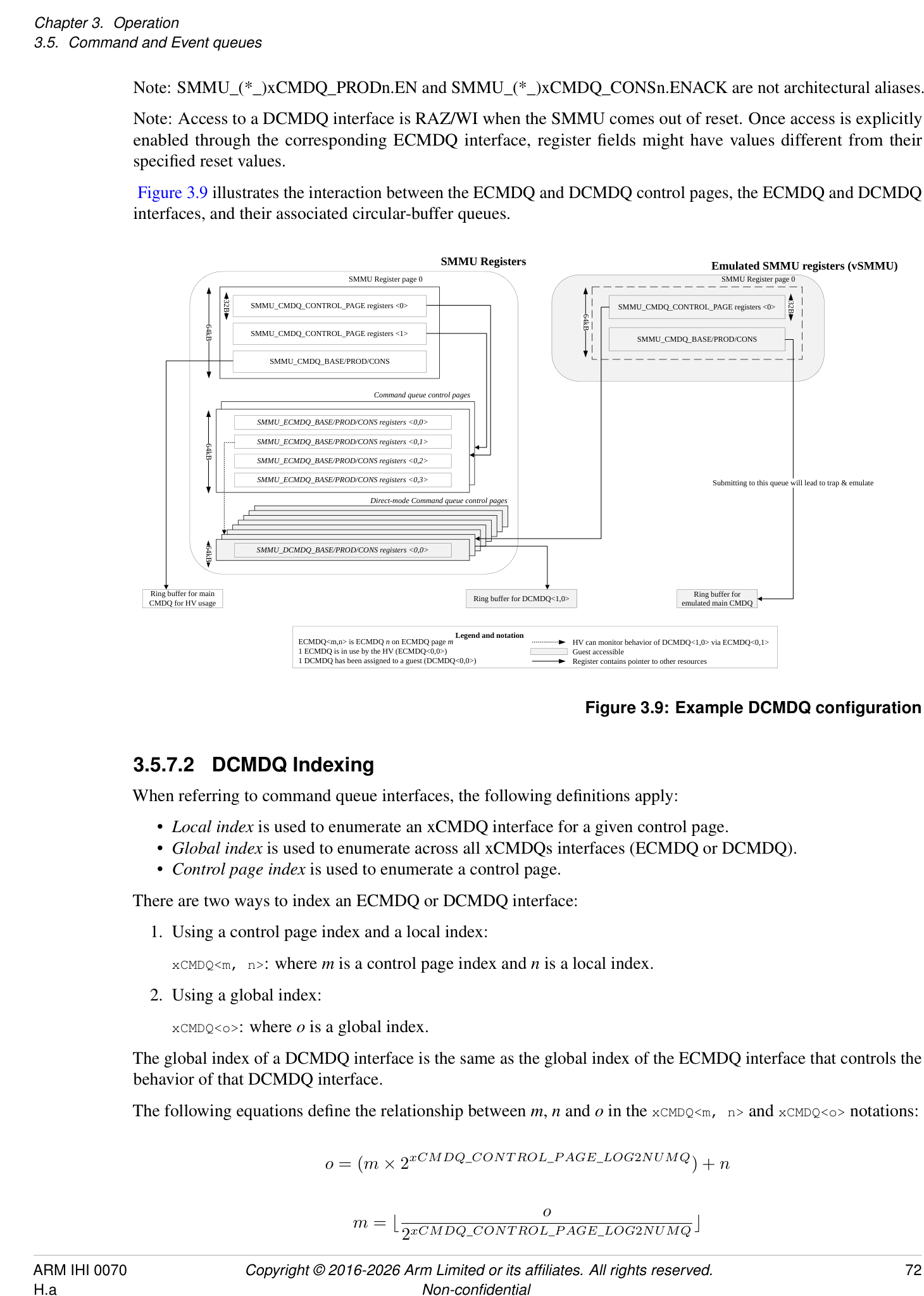
SMMU Registers Emulated SMMU registers (vSMMU)
SMMU Register page 0 SMMU Register page 0
SMMU_CMDQ_CONTROL_PAGE registers <0> SMMU_CMDQ_CONTROL_PAGE registers <0>
SMMU_CMDQ_CONTROL_PAGE registers <1> SMMU_CMDQ_BASE/PROD/CONS
SMMU_CMDQ_BASE/PROD/CONS
Command queue control pages
SMMU_ECMDQ_BASE/PROD/CONS registers <0,0>
SMMU_ECMDQ_BASE/PROD/CONS registers <0,1>
SMMU_ECMDQ_BASE/PROD/CONS registers <0,2>
SMMU_ECMDQ_BASE/PROD/CONS registers <0,3> Submitting to this queue will lead to trap & emulate
Direct-mode Command queue control pages
SMMU_DCMDQ_BASE/PROD/CONS registers <0,0>
CMDQ for HV usageRing buffer for main  Ring buffer for DCMDQ<1,0> emulated main CMDQRing buffer for
ECMDQ<m,n> is ECMDQ  n  on ECMDQ page  m Legend and notation HV can monitor behavior of DCMDQ<1,0> via ECMDQ<0,1>
1 ECMDQ is in use by the HV (ECMDQ<0,0>) Guest accessible
1 DCMDQ has been assigned to a guest (DCMDQ<0,0>) Register contains pointer to other resources
32B 32B
64kB
64kB
64kB
64kB
Figure 3.9: Example DCMDQ configuration
3.5.7.2 DCMDQ Indexing
When referring to command queue interfaces, the following definitions apply:
-
Local index is used to enumerate an xCMDQ interface for a given control page.
-
Global index is used to enumerate across all xCMDQs interfaces (ECMDQ or DCMDQ).
-
Control page index is used to enumerate a control page.
There are two ways to index an ECMDQ or DCMDQ interface:
- Using a control page index and a local index:
xCMDQ<m, n>: where m is a control page index and n is a local index.
- Using a global index:
xCMDQ<o>: where o is a global index.
The global index of a DCMDQ interface is the same as the global index of the ECMDQ interface that controls the behavior of that DCMDQ interface.
The following equations define the relationship between m , n and o in the xCMDQ<m, n> and xCMDQ<o> notations:
The indices must not exceed the number of implemented xCMDQ interfaces:
0 ≤ n < 2 [xCMDQ][] [CONT ROL][] [P AGE][_] [LOG][2] [NUMQ]
0 ≤ o < 2 [xCMDQ][] [CONT ROL][] [P AGE][] [LOG][2] [NUMQ] × 2 [xCMDQ][] [CONT ROL][] [P AGE][] [LOG][2] [NUMP]
3.5.7.3 DCMDQ qSID and STE Association
Each DCMDQ control page has both:
-
An assigned StreamID, referred to as the queue StreamID (qSID) .
-
An associated Stream Table Entry (STE) . The STE is selected by the qSID.
3.5.7.3.1 Queue StreamID (qSID)
The qSID is used for the purpose of issuing translation requests and interrupts associated with the corresponding DCMDQ control page.
The qSID is the concatenation of the upper bits of SMMU_()IDR7.QSID_BASE, as defined by log2nump, and the DCMDQ control page index, where log2nump is SMMU(_)IDR6.DCMDQ_CONTROL_PAGE_LOG2NUMP:
qSID = {SMMU_(*_)IDR7.QSID_BASE[31:log2nump], DCMDQ control page index[log2nump-1:0]}.
All StreamIDs reserved for qSID usage form a contiguous range with a base value specified in SMMU_(*_)IDR7.QSID_BASE.
Arm expects that StreamIDs that fall within this range are never assigned to client devices.
If the StreamID of a client device transaction falls within this range, it is IMPLEMENTATION DEFINED whether:
-
The transaction is silently terminated with an abort.
-
The SMMU translates the client transaction.
Note: If the SMMU translates such a client transaction, the outcome is UNPREDICTABLE. For example, a GPCF might be reported as originating from a DCMDQ transaction.
3.5.7.3.2 Stream Table Entry (STE)
For a DCMDQ to function correctly, a Stream Table Entry (STE) associated with a DCMDQ control page is programmed as follows:
- STE.Config and STE.STRW configure which stages of translation are used to translate the address supplied in SMMU_(*_)DCMDQ_BASEn.ADDR and CMD_SYNC.MSIAddress. Software is expected to set STE.Config to 0b110 (stage 1 bypass, stage 2 translate).
Note: When STE.Config is 0b110, STE.STRW is IGNORED.
-
If SMMU_IDR1.ATTR_TYPES_OVR is 1, software is expected to set STE.{MTCFG, SHCFG} to {0b0, 0b01} so that the cacheability and shareability attributes of the incoming transaction are used. See section 3.5.7.4 DCMDQ Attributes .
-
TLBI commands submitted over the DCMDQ interface are scoped with STE.S2VMID. Software is expected to configure the STE in such a way that STE.S2VMID is not IGNORED.
-
The fault configuration is defined as follows:
-
Software is expected to set STE.S2S to 0b0 (DCMDQ interfaces are not required to support the Stall model).
-
Software is expected to set STE.S2R to 0b1.
-
When an STE associated with a DCMDQ control page is programmed incorrectly, it is IMPLEMENTATION DEFINED whether:
-
The SMMU treats the STE as programmed. Transactions related to the DCMDQ interface will be processed according to the programmed STE, which can result in UNPREDICTABLE behavior.
-
When the configuration of the STE implies STE.S2VMID is IGNORED, then for TLBI commands submitted over the DCMDQ interface, the SMMU is permitted to either:
-
[Perform the invalidation on an][UNKNOWN][ VMID value.]
-
[Not perform an invalidation.]
-
-
When STE.S2S is set to 0b1, DCMDQ transactions will stall upon a fault. This might compromise system stability.
-
-
The SMMU treats STE.S2S as 0b0 and generates a C_BAD_STE event when any of the other STE fields are configured incorrectly.
-
The SMMU generates a C_BAD_STE event when any of the STE fields are configured incorrectly.
Note: In all cases, if the STE is ILLEGAL then a C_BAD_STE event is generated. See section 5.2.2 Validity of STE .
The hypervisor is expected to invalidate the STE before assigning a DCMDQ control page to another guest OS. See section 3.5.7.6 Disabling and Reclaiming DCMDQ control pages .
3.5.7.4 DCMDQ Attributes
When commands are fetched from a DCMDQ, these fetches have all the following properties:
-
The access is a Privileged Data read.
-
The memory attributes are Normal-iWB-oWB-iSH.
-
The Input NS attribute of the access is one of the following:
-
For Non-secure DCMDQs, the access is Non-secure.
-
For Secure DCMDQs, the access is Secure.
-
For Realm DCMDQs, the access is Realm.
-
-
The hints are configured as for an ECMDQ:
-
The Read-Allocate hint is configured in SMMU_(*_)DCMDQ_BASEn.RA.
-
The Transient hint is IMPLEMENTATION DEFINED.
-
The attributes in CMD_SYNC.{MSIAttr, MSH} are the input attributes for the MSI following a CMD_SYNC.
The final attributes of the fetch or MSI are determined by the translation process.
For information on the MECID used for DCMDQ-related accesses, see STE.MECID and SMMU_R_GMECID.
For information on the MPAM attributes used for DCMDQ fetches, see 17.4 Assignment of PARTID and PMG for SMMU-originated transactions .
For details on the cacheability and shareability of memory accesses due to SID translation, see section 3.5.9.1 CIT and VSTT lookup process .
3.5.7.5 Enabling DCMDQ control pages
This section describes the operations performed to enable a DCMDQ control page for use by a guest OS.
3.5.7.5.1 Effects of Updating SMMU_ECMDQ_PROD.EN on a DCMDQ
When SMMU_()ECMDQ_BASEn.DM is 1, setting SMMU(_)ECMDQ_PRODn.EN to 1 has the following effects:
-
It triggers an Update of SMMU_(*_)DCMDQ_PRODn.EN to 0.
-
The subsequent Update of SMMU_()ECMDQ_CONSn.ENACK to 1 guarantees that the Update of SMMU(_)DCMDQ_CONSn.ENACK to 0 has completed.
Note: The Update of SMMU_(*_)DCMDQ_PRODn.EN to 0 guarantees that the DCMDQ will not consume any commands until it is enabled through the DCMDQ interface.
3.5.7.5.2 Software behavior
To enable guest OS access to a DCMDQ control page, the hypervisor performs the following steps:
-
Disable all ECMDQ interfaces to be assigned to the guest OS by setting:
-
SMMU_(*_)ECMDQ_PRODn.EN to 0.
-
SMMU_(*_)ECMDQ_CONSn.ENACK to 0.
-
-
Configure the associated STE and, if SID translation will be enabled for this DCMDQ control page, configure the appropriate memory structures. See section 3.5.9 Virtual to physical SID translation .
-
Mark each ECMDQ to be assigned as in direct-mode by setting:
-
SMMU_(*_)ECMDQ_BASEn.DM to 1.
-
If SID translation will be enabled, SMMU_(*_)ECMDQ_BASEn.VSID to 1.
-
-
Set SMMU_(*_)ECMDQ_CONSn.SYNTH_SYNC_ERR to 0b00.
-
Ensure that SMMU_()DCMDQP_ERRNn and SMMU(_)DCMDQP_ERRn are made consistent. See section 3.5.7.7 DCMDQ Errors and Faults .
-
Activate each DCMDQ interface by setting SMMU_(*_)ECMDQ_PRODn.EN to 1.
-
Following the Update of SMMU_(*_)ECMDQ_CONSn.ENACK to 1 for all ECMDQ interfaces, the DCMDQ control page is active.
3.5.7.6 Disabling and Reclaiming DCMDQ control pages
This section describes the operations performed to reclaim a DCMDQ control page from a guest OS.
In a typical scenario, the guest OS will have been descheduled, and therefore the hardware can be reassigned to another guest OS. However, the hypervisor can reclaim DCMDQ control pages assigned to a guest OS while the circular-buffer queue is not empty.
3.5.7.6.1 Synthesized Synchronization
When software sets SMMU_(*_)ECMDQ_PRODn.EN to 0, it triggers a synthesized synchronization operation that has the following effects:
-
The SMMU stops fetching new commands and only consumes commands from outstanding fetches.
-
This operation is applied only when a DCMDQ is disabled through the ECMDQ interface, i.e.:
-
SMMU_(*_)ECMDQ_BASEn.DM == 1.
-
SMMU_(*_)ECMDQ_PRODn.EN == 0.
-
This operation is not applied if a guest OS disables a DCMDQ, i.e.:
-
[SMMU_(*_)ECMDQ_BASEn][.DM == 1.]
-
[SMMU_(*_)DCMDQ_PRODn][.EN == 0.]
-
-
This operation has equivalent properties to a CMD_SYNC submitted to the queue with CS == 0b00.
-
When the SMMU Updates SMMU_(*_)ECMDQ_CONSn.ENACK to 0, it guarantees all of the following:
-
Errors have been reported and command consumption has stopped; i.e., all of the following fields are stable: SMMU_(*_)ECMDQ_CONSn.{ERR, ERR_REASON, HS_ERR, HS_ERR_REASON, RD, RD_WRAP}.
-
The synthesized synchronization operation is complete.
-
The same synchronization guarantees as for a completed CMD_SYNC apply:
-
The guarantees are made for all successfully consumed commands (those before SMMU_(*_)ECMDQ_CONSn.RD).
-
No guarantees can be made for the command pointed to by SMMU_(*_)ECMDQ_CONSn.RD when either:
-
[An error is active on][ SMMU_(*_)ECMDQ_CONSn][.ERR.]
-
[A hypervisor-serviced error is active on][ SMMU_(*_)ECMDQ_CONSn][.HS_ERR.]
-
-
SMMU_(*_)ECMDQ_CONSn.SYNTH_SYNC_ERR is set as follows:
-
[When][one][or][more][CMD_ATC_INV][commands][since][the][last][synchronization][operation][timed] out and this has not been reported as CERROR_ATC_INV_SYNC, this is reported by setting SMMU_(*_)ECMDQ_CONSn.SYNTH_SYNC_ERR[0] to 1.
-
[When][the][MSI][write][of][the][prior][CMD_SYNC][consumed][on][the][DCMDQ][has][aborted] and this has not been reported as HERROR_MSI_ABT, this is reported by setting SMMU_(*_)ECMDQ_CONSn.SYNTH_SYNC_ERR[1] to 1.
-
-
-
[Setting][any][bit][in][SMMU_()ECMDQ_CONSn][.SYNTH_SYNC_ERR][to][1][does][not][affect] SMMU()DCMDQP_ERRn or SMMU(*_)GERROR.DCMDQP_ERR.
-
[Once][an][error][has][been][reported][in][SMMU_()ECMDQ_CONSn][.SYNTH_SYNC_ERR,][the] SMMU does not report it on subsequent synchronization operations on the DCMDQ. Note: Once the SMMU has set a bit in SMMU()ECMDQ_CONSn.SYNTH_SYNC_ERR, it is the responsibility of the hypervisor to report the corresponding error to the guest OS or take any other corrective action. If SMMU()ECMDQ_CONSn.SYNTH_SYNC_ERR does not equal 0b00 when a DCMDQ is enabled, it is CONSTRAINED UNPREDICTABLE whether SMMU(_)ECMDQ_CONSn.SYNTH_SYNC_ERR will correctly report an error condition upon a synthesized synchronization operation.
3.5.7.6.2 Software behavior
To disable or reclaim a DCMDQ control page from a guest OS, software is expected to perform the following steps:
-
Unmap the DCMDQ control page so that the guest OS can no longer access it.
-
Emulate the page and trap any updates to SMMU_(*_)ECMDQ_PRODn pointers.
-
Disable each DCMDQ by setting SMMU_(*_)ECMDQ_PRODn.EN to 0. This has the effect described in 3.5.7.6.1 Synthesized Synchronization .
-
Once all queues on the page have been disabled, the hypervisor must ensure that the data structures associated with the qSID have been invalidated, both in memory and any cached copies in the SMMU:
-
The cached copies of the STE are invalidated by issuing CMD_CFGI_STE.
-
Any cached copies of Command Queue Information Table (CIT) and vSID Translation Table (VSTT) entries used during SID translation are invalidated using CMD_CFGI_CIT. See section 3.5.9.3 Caching and invalidation of vSID translation structures .
-
This is followed by a CMD_SYNC to ensure all previous commands have completed successfully.
-
Note: All of these commands are issued to a command queue assigned to the hypervisor.
3.5.7.7 DCMDQ Errors and Faults
This section describes the handling of errors and faults for DCMDQs.
An error reported in any of the following registers is referred to as a command queue error :
-
SMMU_(*_)CMDQ_CONS.
-
SMMU_(*_)ECMDQ_CONSn.
-
SMMU_(*_)DCMDQ_CONSn.
Upon a command queue error, command consumption stops and an error is reported.
When SMMU_(*_)IDR6.DCMDQ == 0b01:
-
Command queue errors reported through SMMU_(*_)DCMDQ_CONSn.{ERR, ERR_REASON} are referred to as guest-serviced errors and are handled by the guest OS. See section 3.5.7.7.2 Guest-serviced errors .
-
Command queue errors reported through SMMU_(*_)ECMDQ_CONSn.{HS_ERR, HS_ERR_REASON} are referred to as hypervisor-serviced errors and are handled by the hypervisor. See section 3.5.7.7.3 Hypervisor-serviced errors .
The SMMU never reports a guest-serviced error and a hypervisor-serviced error concurrently. Specifically, if a command causes a CERROR_ILL, this takes precedence over the reporting of a hypervisor-serviced error.
For a summary of errors that can occur on a DCMDQ, see 7.1.1 Direct-mode Enhanced Command Queue error summary .
3.5.7.7.1 Error reporting for DCMDQ control pages
The following registers are used for reporting that a DCMDQ control page has one or more DCMDQ interfaces with an active error:
-
SMMU_(*_)DCMDQP_ERRn, the error reporting register.
-
SMMU_(*_)DCMDQP_ERRNn, the error acknowledge register.
If the number of implemented DCMDQ control pages is m , then ⌈ 64 [m][⌉][pairs of these registers are implemented,] where register pair n reports errors on DCMDQ control pages n × 64 to [( n + 1) × 64] − 1.
When the value of SMMU_()DCMDQP_ERRn.DCMDQP_ERRp is different from the value of SMMU(_)DCMDQP_ERRNn.DCMDQP_ERRNp, one or more DCMDQ interfaces associated with DCMDQ control page n × 64 + p have encountered a command that cannot be processed.
If another DCMDQ interface associated with the same DCMDQ control page reports an error, the SMMU does not toggle SMMU_(*_)DCMDQP_ERRn.DCMDQP_ERRp again.
If SMMU_()DCMDQP_ERRn.DCMDQP_ERRp and SMMU(_)DCMDQP_ERRNn.DCMDQP_ERRNp differ when enabling a corresponding DCMDQ interface, it is CONSTRAINED UNPREDICTABLE whether the SMMU correctly reports subsequent errors through these registers. The following process will restore regular behavior:
-
Disable the DCMDQ.
-
Make both registers consistent.
-
Re-enable the DCMDQ.
Errors on a DCMDQ are always reported and acknowledged through SMMU_()GERROR.DCMDQP_ERR and SMMU(_)GERRORN.DCMDQP_ERR respectively.
Note: SMMU_()GERROR.CMDQP_ERR does not report errors on an SMMU()DCMDQP_ERRn or SMMU(*_)DCMDQP_ERRNn register.
3.5.7.7.2 Guest-serviced errors
When a guest-serviced error occurs during command consumption, all of the following occur:
-
The SMMU toggles the value of SMMU_()DCMDQ_CONSn.ERR and sets SMMU(_)DCMDQ_CONSn.ERR_REASON to indicate the reason for the error.
-
The error is additionally reported in SMMU_(*_)DCMDQP_ERRm, where m represents the DCMDQ control page, if it is not already active.
-
If the bit representing the DCMDQ control page was not already active, the error is additionally reported in SMMU_GERROR.DCMDQP_ERR, if SMMU_GERROR.DCMDQP_ERR is not already active.
-
If SMMU_GERROR.DCMDQP_ERR was not already active, a GERROR interrupt is raised according to the configuration in SMMU_GERROR_IRQ_CFG*.
Because SMMU_()GERROR, SMMU(_)DCMDQP_ERRm, and the GERROR interrupt are not visible to the guest OS, the hypervisor needs to pass this on to the guest OS via the emulated SMMU register pages and inject a GERROR interrupt into the guest OS.
Note: The hypervisor must acknowledge an error through SMMU_()GERRORN and SMMU(_)DCMDQP_ERRn before injecting a GERROR interrupt into the guest OS, to prevent the loss of an error event.
Note: Resuming command consumption on a DCMDQ is not affected by the value of any of the following registers:
-
SMMU_()DCMDQP_ERRn and SMMU(_)DCMDQP_ERRNn.
-
SMMU_()GERROR.DCMDQP_ERR and SMMU(_)GERRORN.DCMDQP_ERR.
Command consumption on the command queue where the error is present restarts once the error has been acknowledged, depending on the error type, either by:
-
The guest OS through SMMU_(*_)DCMDQ_PRODn.ERRACK.
-
The hypervisor through SMMU_(*_)ECMDQ_PRODn.HS_ERRACK.
In any of the following cases, it is CONSTRAINED UNPREDICTABLE whether the SMMU consumes commands from a queue and whether a subsequent error is correctly reported:
- The error status acknowledgment bits on an enabled queue (SMMU_()ECMDQ_PRODn.{ERRACK, HS_ERRACK} or SMMU(_)DCMDQ_PRODn.ERRACK) are inappropriately configured such that
they mismatch the corresponding error status bit (SMMU_()ECMDQ_CONSn.{ERR, HS_ERR} or SMMU(_)DCMDQ_CONSn.ERR).
-
A queue is enabled using SMMU_()DCMDQ_PRODn.EN while SMMU()DCMDQ_PRODn.ERRACK mismatches SMMU(*_)DCMDQ_CONSn.ERR.
-
A queue is enabled using SMMU_()ECMDQ_PRODn.EN while SMMU()ECMDQ_PRODn.HS_ERRACK mismatches SMMU(*_)ECMDQ_CONSn.HS_ERR.
If a queue is enabled using SMMU_()DCMDQ_PRODn.EN and a hypervisor-serviced error is active (that is, SMMU()ECMDQ_PRODn.HS_ERRACK mismatches SMMU(*_)ECMDQ_CONSn.HS_ERR), then the SMMU does not consume commands from the queue until the hypervisor restarts command consumption by acknowledging the error.
3.5.7.7.3 Hypervisor-serviced errors
Hypervisor-serviced errors are handled as follows:
-
When a fault or configuration error is encountered during address translation for a command queue fetch or an MSI, the transaction is terminated with an abort. In addition, if the Event queue is writable, an Event is recorded. This applies for all of the following faults. Any faults not listed are not applicable to these types of transactions:
-
Configuration errors (C_BAD_STE, C_BAD_STREAMID).
-
Faults during STE fetch (F_STE_FETCH).
-
Faults due to cache-related conflicts (F_TLB_CONFLICT, F_CFG_CONFLICT).
-
Faults due to external aborts during translation walks (F_WALK_EABT).
-
Faults during translation (F_TRANSLATION, F_PERMISSION, F_ADDR_SIZE and F_ACCESS). The hypervisor is expected to enforce this behavior by setting: – STE.S2S to 0.
- STE.S2R to 1.
-
-
SMMU_(*_)ECMDQ_CONSn.HS_ERR is toggled to indicate an active error.
-
SMMU_(*_)ECMDQ_CONSn.HS_ERR_REASON is set to HERROR_IPA.
-
When the error is observable through both SMMU_()ECMDQ_CONSn.HS_ERR and SMMU(_)ECMDQ_CONSn.HS_ERR_REASON, the completion of a CMD_SYNC on any queue guarantees that the Event record is either:
-
Visible in the Event queue.
-
Discarded if the Event could not be written to the Event queue due to the queue not being writable. Note: This is in line with the behavior of an unrecorded fault event record relating to a client transaction terminated by the SMMU whose abort or termination response could have been observed by the client device before the start of the CMD_SYNC.
-
-
The error is additionally reported using SMMU_(*_)DCMDQP_ERRn
and SMMU_(*_)GERROR.DCMDQP_ERR, as described in 3.5.7.7 DCMDQ Errors and Faults .
Once the hypervisor has fixed the behavior causing the hypervisor-serviced error, SMMU_(*_)ECMDQ_PRODn.HS_ERRACK is used to:
-
Acknowledge the error.
-
Indicate to the SMMU that the command fetch (and corresponding address translation) can be retried.
In the case of Event queue overflow where the hypervisor has no visibility of the event related to the hypervisor-serviced error, the hypervisor is expected to resolve the overflow and restart the queue so that the subsequent retry can result in a hypervisor-serviced error being recorded in the Event queue.
Note: For more information on:
-
Errors during SID translation, see section 3.5.9.4 vSID Errors and external aborts .
-
The reporting of an aborted MSI following a CMD_SYNC, see section 3.5.7.7.4 DCMDQ MSIs .
If SMMU_ROOT_IDR0.ROOT_IMPL == 1 and SMMU_ROOT_CR0.GPCEN == 1, all accesses introduced by the DCMDQ feature are subject to granule protection checks. See 3.25 Granule Protection Checks .
A GPC fault on any DCMDQ-related access is handled as a GPC fault on an SMMU-originated access and is additionally reported as a hypervisor-serviced error. For information on error codes, see section 3.25.7 DCMDQ-related GPC faults .
An implementation is permitted to:
-
Read or prefetch translation entries for any commands ahead of SMMU_()DCMDQ_CONSn.RD and up to SMMU(_)DCMDQ_PRODn.WR.
-
Request translations ahead of SMMU_(*_)DCMDQ_PRODn.WR, but it must not report any faults or errors for these translations.
When a fault or configuration error is encountered during an address translation for such an operation, the SMMU is permitted, but not required, to generate Event records or to report a GPC fault.
Note: When a DCMDQ stops consuming commands because of an error or fault, SMMU_()ECMDQ_CONSn.RD will point to the oldest command that has an unresolved error. Software might therefore observe more than one Event or GPC fault due to translation requests for commands between SMMU()DCMDQ_CONSn.RD and SMMU()DCMDQ_PRODn.WR, where only one of these is associated with the error reported in the SMMU(_)ECMDQ_CONSn register.
3.5.7.7.4 DCMDQ MSIs
The completion of a CMD_SYNC on a DCMDQ is signalled using an MSI if CMD_SYNC.CS == SIG_IRQ. In this case, completion of the CMD_SYNC leads to an SMMU-generated MSI controlled by a guest OS, where the SMMU uses the MSIData, MSIAddress and MSIAttr fields provided in the CMD_SYNC to generate the MSI. This is subject to SMMU translation.
Note: If CMD_SYNC.{CS, MSIAddress} == (SIG_IRQ, zero), then no interrupt is generated.
The DeviceID associated with an MSI that is triggered by a CMD_SYNC on a DCMDQ is generated from the qSID of the corresponding DCMDQ control page, in an IMPLEMENTATION DEFINED manner.
Note: This produces a unique DeviceID that does not overlap with DeviceIDs produced for client devices, or for other SMMU-originated MSIs. It allows the GIC ITS to differentiate between SMMU-generated MSIs that are under either hypervisor control or guest OS control.
The EventID passed to the GIC ITS is generated from CMD_SYNC.MSIData and is therefore under guest OS control.
The SMMU ignores the value of CMD_SYNC.MSI_NS, and the target PA space of the MSI is determined by both of the following:
-
STE[qSID].
-
The SMMU translation process.
An implementation must not assert wired interrupts upon completion of a CMD_SYNC on a DCMDQ. Completion may only be signalled through an MSI. The hypervisor is expected to present an emulated SMMU to the guest OS which only supports interrupts through MSIs. This means that in the emulated SMMU, the hypervisor:
-
Sets SMMU_(*_)IDR0.MSI to 1.
-
Does not advertise support for wired interrupts.
When an MSI triggered by a CMD_SYNC consumed on a DCMDQ is aborted:
-
The next CMD_SYNC on this DCMDQ does not complete.
-
Command consumption stops and an error is reported to the hypervisor by toggling SMMU_()ECMDQ_CONSn.HS_ERR and setting SMMU(_)ECMDQ_CONSn.HS_ERR_REASON to HERROR_MSI_ABT.
-
The CMD_SYNC completes after the hypervisor acknowledges the error.
SMMU_(*_)GERROR.MSI_CMDQ_ABT_ERR does not report aborted MSI writes for CMD_SYNCs that are consumed on DCMDQs.
The hypervisor is responsible for informing the guest OS about the aborted MSI via the emulated view of SMMU_(*_)GERROR.MSI_CMDQ_ABT_ERR. To meet the completion guarantees of a CMD_SYNC from the perspective of the guest OS, the hypervisor is expected to acknowledge the error and restart command consumption only after doing so.
3.5.8 Restricted Command Queues
This section applies only when SMMU_(*_)IDR2.RECMDQ is 1.
A RECMDQ is an ECMDQ with restricted capabilities.
RECMDQs can be used for presenting a DCMDQ to a guest OS.
The set of commands supported by a RECMDQ is explicitly advertised using the SMMU_()IDR2.ECMDQ_CMD fields.
Commands that are not supported by a RECMDQ can still be submitted to the main command queue.
If software submits an unsupported command to a RECMDQ, then:
-
The command is not consumed.
-
The SMMU returns CERROR_ILL through the RECMDQ interface.
The attributes in SMMU_(*_)CR1.{QUEUE_IC, QUEUE_OC, QUEUE_SH} do not apply to RECMDQs. Fetches through an RECMDQ interface are Inner Write-back Cacheable, Outer Write-back Cacheable, Inner Shareable.
If software acknowledges an error observable in SMMU_()ECMDQ_CONSn.ERR before SMMU()GERROR.CMDQP_ERR is observable, it is CONSTRAINED UNPREDICTABLE whether the SMMU activates SMMU(*_)GERROR.CMDQP_ERR.
Prefetch and synchronization commands are always permitted on a RECMDQ.
All other behavior is identical to that of regular ECMDQs as described in 3.5.6 Enhanced Command queue interfaces .
Note: Software may have to split a single sequence of commands across different command queues, depending on the command types supported on each queue. Software must perform the necessary synchronization operations on a per-queue granularity to maintain the ordering properties of the sequence as a whole. For example, by waiting for the completion of a CMD_SYNC on one queue before issuing a command on another queue.
3.5.9 Virtual to physical SID translation
This section applies only when SMMU_(R_)IDR6.VSID is 0b01.
If the SMMU supports both DCMDQs and ATS, it can optionally support translation of StreamIDs (SIDs).
This allows the hypervisor to expose a virtual StreamID space to a guest OS, therefore allowing the guest OS to issue ATS Invalidations and PRG responses over a DCMDQ.
Virtual SIDs (vSIDs) that are supplied by the guest OS in ATS-related commands and prefetch commands are translated by the SMMU into physical SIDs (pSIDs) .
When SID translation is enabled, the hypervisor can signal to a guest OS that ATC and PRI commands are supported by presenting an emulated view of the following register fields (configured accordingly):
-
SMMU_(*_)IDR2.ECMDQ_CMD_ATC.
-
SMMU_(*_)IDR2.ECMDQ_CMD_PRI.
Note: A guest OS is always permitted to submit prefetch commands to the DCMDQs.
SID translation is performed using a vSID Translation Table (VSTT) structure. This is a 2-level table which has a setup similar to the Stream Table.
Each guest OS has their own VSTT.
Indexing into the VSTT is performed using the vSID of the command being consumed.
The VSTT base address can be found through the Command Queue Information Table (CIT) structure. This table has a setup similar to the Stream table and might be a 2-level table. The CIT holds the configuration of each VSTT.
Indexing into the CIT is performed using the qSID associated with a command queue control page.
Access to the structures required for SID translation is Guarded by SMMU_(*_)CR0.VSIDEN.
3.5.9.1 CIT and VSTT lookup process
Figure 3.10 shows the table walks needed for SID translation, in the case of a 2-level CIT. The configuration information for the first fetch is held in registers, and all other configuration information is held in memory structures.
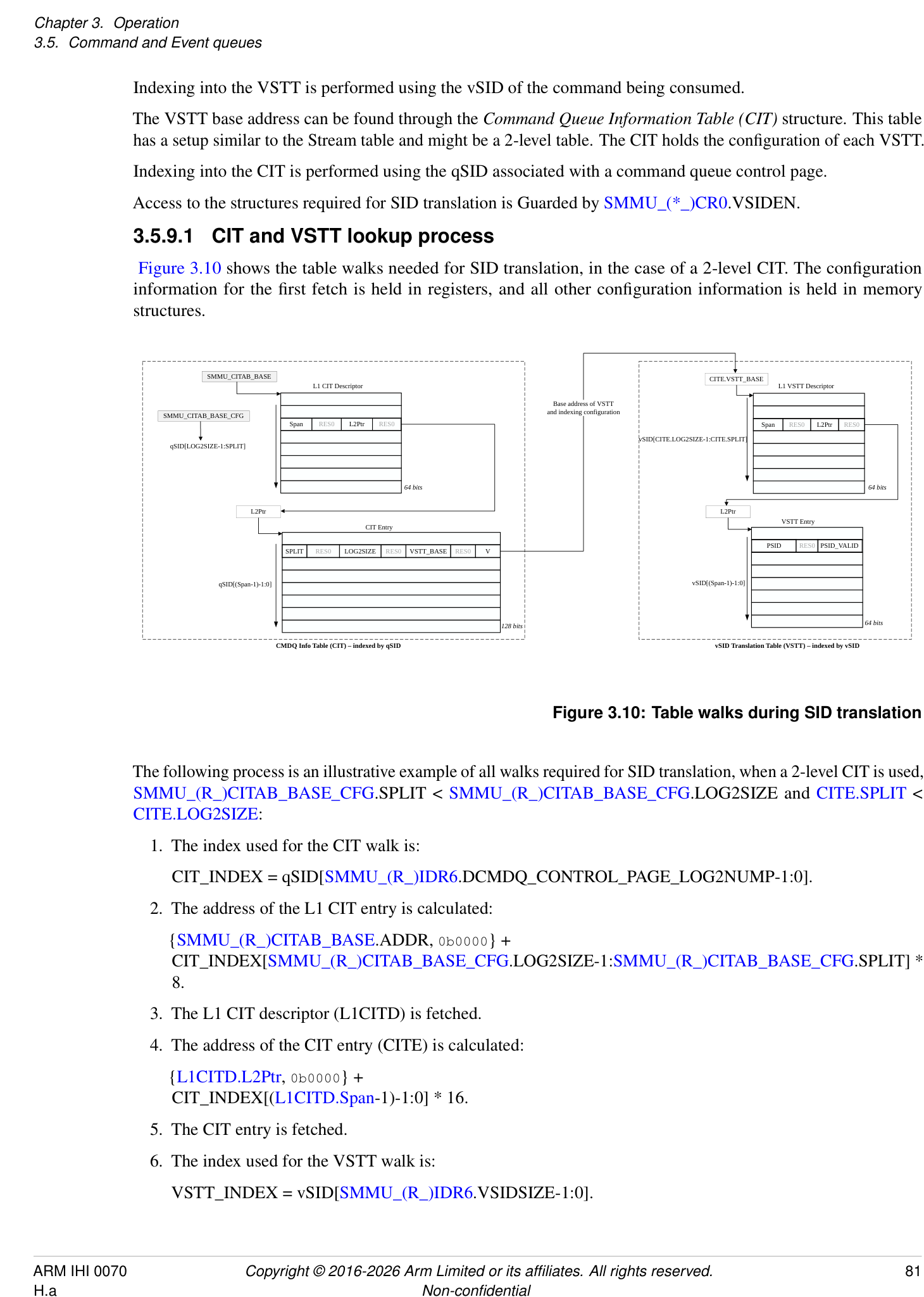
SMMU_CITAB_BASE CITE.VSTT_BASE
L1 CIT Descriptor L1 VSTT Descriptor
Base address of VSTT
SMMU_CITAB_BASE_CFG and indexing configuration
Span RES0 L2Ptr RES0 Span RES0 L2Ptr RES0
vSID[CITE.LOG2SIZE-1:CITE.SPLIT]
qSID[LOG2SIZE-1:SPLIT]
64 bits 64 bits
L2Ptr L2Ptr
CIT Entry VSTT Entry
SPLIT RES0 LOG2SIZE RES0 VSTT_BASE RES0 V PSID RES0 PSID_VALID
qSID[(Span-1)-1:0] vSID[(Span-1)-1:0]
128 bits 64 bits
CMDQ Info Table (CIT) – indexed by qSID vSID Translation Table (VSTT) – indexed by vSID
Figure 3.10: Table walks during SID translation
The following process is an illustrative example of all walks required for SID translation, when a 2-level CIT is used, SMMU_(R_)CITAB_BASE_CFG.SPLIT < SMMU_(R_)CITAB_BASE_CFG.LOG2SIZE and CITE.SPLIT < CITE.LOG2SIZE:
- The index used for the CIT walk is:
CIT_INDEX = qSID[SMMU_(R_)IDR6.DCMDQ_CONTROL_PAGE_LOG2NUMP-1:0].
-
The address of the L1 CIT entry is calculated:
- {SMMU_(R_)CITAB_BASE.ADDR, 0b0000} +
CIT_INDEX[SMMU_(R_)CITAB_BASE_CFG.LOG2SIZE-1:SMMU_(R_)CITAB_BASE_CFG.SPLIT] * 8.
-
The L1 CIT descriptor (L1CITD) is fetched.
-
The address of the CIT entry (CITE) is calculated:
- {L1CITD.L2Ptr, 0b0000} + CIT_INDEX[(L1CITD.Span-1)-1:0] * 16.
-
The CIT entry is fetched.
-
The index used for the VSTT walk is:
VSTT_INDEX = vSID[SMMU_(R_)IDR6.VSIDSIZE-1:0].
-
The address of the L1 VSTT descriptor (L1VSTTD) is calculated:
- {CITE.VSTT_BASE, 0b0000} +
VSTT_INDEX[CITE.LOG2SIZE-1:CITE.SPLIT] * 8.
-
The L1 VSTT descriptor (L1VSTTD) is fetched.
-
The address of the VSTT entry (VSTTE) is calculated:
- {L1VSTTD.L2Ptr, 0b0000} + VSTT_INDEX[(L1VSTTD.Span-1)-1:0] * 8.
-
The VSTT entry is fetched.
Note: Certain bits in SMMU_(R_)CITAB_BASE.ADDR, L1CITD.L2Ptr, CITE.VSTT_BASE and L1VSTTD.L2Ptr might be treated as zero due to address size and alignment restrictions, as defined in the register field descriptions.
3.5.9.2 Attributes used during vSID translation
The cacheability and shareability of memory accesses during SID translation are determined by the SMMU_(R_)CR1.{QUEUE_IC, QUEUE_OC, QUEUE_SH} attributes.
The Read-Allocate hint for an access to the CIT and the VSTTs is provided by SMMU_(R_)CITAB_BASE.RA.
If MPAM is supported, the MPAM attributes for CIT fetches and VSTT fetches are determined by SMMU_(R_)GMPAM.{SO_PMG, SO_PARTID}.
If MEC is supported, the MECID for CIT fetches and VSTT fetches are determined by SMMU_R_GMECID.GMECID.
3.5.9.3 Caching and invalidation of vSID translation structures
An implementation is permitted, but not required, to cache the information held in the CIT (descriptors and entries) and the VSTT (descriptors and entries).
The following commands can be used to invalidate this cached information:
-
CMD_CFGI_CIT.
-
CMD_CFGI_VSTT.
-
CMD_CFGI_VSTT_VSID.
-
CMD_CFGI_ALL.
-
CMD_CFGI_STE_RANGE(Range == 31).
The Security state of the queue to which these commands are issued determines the Security state of the cached entries that are invalidated.
Completion of a CMD_SYNC guarantees that these commands have completed and that the matching cached configuration entries have been invalidated.
Completion of a CMD_SYNC does not guarantee that DCMDQ commands that required SID translation using any of the cached configuration entries targeted by these invalidation operations have completed. Completion of the commands requiring SID translation can only be guaranteed by disabling the DCMDQ associated with the targeted cached configuration entries (that is, by setting SMMU_(*_)ECMDQ_PRODn.EN to 0), thereby triggering a synthesized synchronization operation.
Note: Providing a StreamID or vSID in these commands that is out of range has one of the following CONSTRAINED UNPREDICTABLE behaviors:
-
The command has no effect.
-
The command has an effect, taking an UNPREDICTABLE value for the parameter that is out of range.
A StreamID is out of range if it exceeds the implemented StreamID size as reported by SMMU_IDR1.SIDSIZE.
A vSID is out of range if it exceeds the implemented vSID size as reported by SMMU_(R_)IDR6.VSIDSIZE.
The SMMU_S_INIT.INV_ALL register field invalidates all caches and TLB contents. This includes any caches used for SID translation.
3.5.9.4 vSID Errors and external aborts
In addition to the behavior described in 3.5.7.7 DCMDQ Errors and Faults , the following scenarios may occur when a command requiring SID translation is submitted to a DCMDQ:
-
When SMMU_()IDR6.VSID == 0b00 or SMMU(_)ECMDQ_BASEn.VSID == 0, the behavior depends on the command type:
-
CMD_ATC_INV and CMD_PRI_RESP are ILLEGAL, and this is reported through SMMU_(*_)ECMDQ_CONSn.ERR_REASON as CERROR_ILL.
-
CMD_PREFETCH_* commands which are not otherwise ILLEGAL are IGNORED.
-
-
When an error occurs during the SID translation process, this is reported through SMMU_(R_)ECMDQ_CONSn.ERR_REASON as HERROR_SID_CONFIG in any of the following cases:
-
The CIT or VSTT structures cannot be accessed.
-
The CITE required for this SID translation is invalid.
-
qSID[SMMU_(R_)CITAB_BASE_CFG.SPLIT-1:0] >= 2[L1CITD.Span][-1] .
-
L1CITD.Span == 0.
-
L1CITD.Span > (SMMU_(R_)CITAB_BASE_CFG.SPLIT + 1).
-
L1VSTTD.Span > (CITE.SPLIT + 1).
-
-
When the qSID is out of range (qSID >= 2[SMMU_(R_)CITAB_BASE_CFG][.LOG2SIZE] ), it is CONSTRAINED UNPREDICTABLE if the SMMU uses an UNPREDICTABLE qSID or HERROR_SID_CONFIG is raised. Note: For example, an implementation might truncate the upper bits of the qSID.
-
For all commands that require SID translation, in any of the following cases the command is IGNORED and no error is reported:
-
VSTTE.PSID_VALID == 0.
-
vSID[CITE.SPLIT-1:0] >= 2[L1VSTTD.Span][-1] .
-
L1VSTTD.Span == 0.
-
-
When the vSID is out-of-range because:
-
vSID >= 2[SMMU_(R_)IDR6][.VSIDSIZE] , the command is IGNORED and no error is reported.
-
vSID < 2[SMMU_(R_)IDR6][.VSIDSIZE] and vSID >= 2[CITE.LOG2SIZE] , it is CONSTRAINED UNPREDICTABLE if the SMMU uses an UNPREDICTABLE vSID or the command is IGNORED. Note: For example, an implementation might truncate the upper bits of the vSID.
-
-
An external abort encountered during the table walking of the CIT or VSTT is reported through SMMU_(R_)ECMDQ_CONSn.HS_ERR as HERROR_SID_EABT.
The software guidance in 3.5.7.7 DCMDQ Errors and Faults can be followed to resolve any of the error behaviors described in this section.
For a summary of vSID errors, see 7.1.1 Direct-mode Enhanced Command Queue error summary .
3.6 Structure and queue ownership
Arm expects that the Non-secure Stream table, Command queues, Event queue and PRI queue are controlled by the most privileged Non-secure system software.
If present, Arm expects that the Secure Stream table, Secure Command queue and Secure Event queue are controlled by Secure software. For example, these would be controlled by software in EL3 if a separation in control between Secure EL1 and EL3 is required.
Arm expects that the stage 2 translation tables indicated by all STEs are controlled by a hypervisor.
The ownership of stage 1 CDs and translation tables depends on the configuration in use. If pointed to by a Secure STE, they are controlled by Secure software (one of EL3, S-EL2, or S-EL1). If pointed to by a Non-secure STE, they are controlled by Non-secure software (either NS-EL2 or NS-EL1). If pointed to by a Realm STE, they are controlled by Realm software (either Realm-EL2 or Realm-EL1).
Note: For example, the context might be one of the following:
-
Used by a bare-metal OS, which controls the descriptor and translation tables and is addressed by PA.
-
Used internally by a hypervisor, which controls the descriptor and translation tables and is addressed by PA.
-
Used by a guest, in which case Arm expects that the CD and translation tables are controlled by the guest, and addressed by IPA.
Note: When a hypervisor is used in a given Security state, Arm expects that the Event queue for that Security state is managed by the hypervisor, which forwards events into guest VMs as appropriate. StreamIDs might be mapped from physical to virtual equivalents during this process.
In virtualized scenarios, Arm expects a hypervisor to:
-
Convert guest STEs into physical SMMU STEs, controlling permissions and features as required.
-
Note: The physical StreamIDs might be hidden from the guest, which would be given virtual StreamIDs, so a mapping between virtual and physical StreamIDs must be maintained.
-
Read and interpret commands from the guest Command queue. These might result in commands being issued to the SMMU or invalidation of internal shadowed data structures.
-
Consume new entries from the PRI and Event queues, mapping from host StreamIDs to guest, and deliver appropriate entries to guest Event and PRI queues.
See section 3.8 Virtualization .
3.7 Programming registers
The SMMU registers occupy a set of contiguous 64K pages of system address space that contain mechanisms for discovering capabilities and configuring pointers to in-memory structures and queues. After initialization, runtime access to the registers is generally limited to maintenance of the Command, Event and PRI queue pointers and interaction with the SMMU is performed using these in-memory queues.
Optional regions of IMPLEMENTATION DEFINED register space are supported in the memory map.
See section 6.1 Memory map for register definitions and layout.
3.8 Virtualization
Devices can be put under direct guest control with stage 2-only mappings, without requiring guest interaction with the SMMU. To the guest OS, they appear as though the device is directly connected and might request DMA to PAs (IPAs) directly.
The SMMU does not provide programming interfaces for use directly by virtual machines. Arm expects that, where stage 1 facilities are required for use by a guest in virtualization scenarios, this is supported using hypervisor emulation of a virtual SMMU, or a similar interface for use by a virtual machine.
Implementations might provide an IMPLEMENTATION DEFINED number of extra hardware interfaces that are located in an IMPLEMENTATION DEFINED manner but are otherwise compatible with the SMMUv3 programming interface. Each interface might be mapped through to a guest VM for it to use directly, for example appearing as a stage 1-only interface to the guest while the hypervisor interface appears as stage 2-only. The management of such an implementation is beyond the scope of this specification.
3.9 Support for PCI Express, PASIDs, PRI, and ATS
A PCI RequesterID maps directly to the low-order bits of a StreamID, therefore maps to one STE, see section 3.2 Stream numbering . A PCIe Function is then the minimum granularity that can be assigned to a VM. The PCIe PASID prefix allows a Function to be subdivided into parts, each of which is intended to be assigned to a different user space process at stage 1. The prefix is optional. Transactions from one StreamID might be supplied with a SubstreamID or not, on a per-transaction basis. Because the prefix just identifies a portion of a Function, the Function remains otherwise indivisible and remains the granularity at which assignments to VMs are made. Therefore, in PCI terms:
-
Stage 2 is associated with a RequesterID (identifying a Function). The Function is assigned to a VM.
-
Stage 1 is associated with a (RequesterID, PASID) tuple. That is, the PASID differentiates between different stage 1 translation contexts.
-
The PASID identifies which of the parts or contexts of the Function are assigned to which process or driver at stage 1.
-
If transactions from a Function are translated using stage 2 but stage 1 is unused and in bypass, there are no stage 1 translation contexts to differentiate with a PASID. Supply of a PASID or SubstreamID to a configuration without stage 1 translation causes the translation to fail. Such transactions are terminated with an abort and C_BAD_SUBSTREAMID is recorded.
PASIDs can be up to 20 bits in size. PASIDs are optional, configurable, and of a size determined by the minimum of the endpoint, system software, PCIe Root Complex and the individually-supported substream width of the SMMU.
The SMMU is not required to report an error in the case where an endpoint and Root Complex emit a PASID with a value greater than can be expressed in the SubstreamID width supported by the SMMU. In this scenario, the PASID might be truncated to the SubstreamID size on arrival at the SMMU.
To minimize PCIe-specific terms, a RequesterID is referred to using a StreamID (to which the RequesterID maps in a hardware-specific manner). In the SMMU, a PASID is referred to as a SubstreamID. Even when a client device supports SubstreamIDs, it is not mandatory to supply a SubstreamID with all transactions from that device. PCIe permits a PASID to be supplied, or not, on a per-transaction basis. Therefore, where a SubstreamID is input to the SMMU, a validity flag is also provided and this is asserted when a PASID is present.
The PASID tag provides additional permission attributes on top of the standard PCIe read/write attribute. The tag can express an Execute and Privileged state that correspond to the SMMU INST and PRIV attributes. A PCIe transaction without a PASID is considered Data, unprivileged. The mapping between PCIe and SMMU permissions is described in section 13.7 PCIe permission attribute interpretation .
3.9.1 ATS Interface
An optional extra hardware interface might be provided by an SMMU implementation to support PCIe ATS [1] and PRI. This interface conveys translation and paging requests and responses to and from the PCIe Root Complex, which bridges requests and responses into the PCIe domain.
Whether the SMMU implements ATS can be discovered from SMMU_(R_)IDR0.ATS. If ATS is implemented, whether the SMMU also implements PRI can be discovered from SMMU_(R_)IDR0.PRI. This support determines the behavior of SMMU-local configuration and commands but does not guarantee that the rest of the system, and all clients of an SMMU, also support ATS and PRI. The ATS and PRI capabilities of dependent PCIe Root Complexes and endpoints thereof are discovered through other means.
PCIe ATS has the following properties:
-
Note: ATS aims to improve the performance of a system using an SMMU, known as a Translation Agent in PCIe terminology, by caching translations within the endpoint or Requester. This can remove contention on a shared TLB, or reduce latency by helping the device to request translation ahead of time.
-
The remote endpoint Address Translation Cache (ATC, which is equivalent to a TLB) is filled on-demand by making a Translation Request to the Root Complex which forwards it to the SMMU. If the translation exists
and permission checks pass, a Translation Completion response is given with a Physical Address and the ATC caches this response.
-
The return of a translated, physical address to an endpoint grants the endpoint permission to access the physical address. The endpoint can now make direct access to PAs, which it does by tagging outgoing traffic as Translated. The Root Complex is expected to provide this tag to the SMMU. The SMMU might then allow such transactions to bypass translation and access PA space directly.
-
If a Translation Request would result in a fault or error, a negative response is returned and the endpoint is not able to access the address using ATS. This denial might be fatal to the endpoint, reported in a device-specific manner, or when PRI is used, initiate a page-in request.
-
Page access permission checking is performed at the time of the Translation Request, and takes the form of a request for permission to read or to read/write (and, optionally, to execute). The response grants the device access to read or to read/write (and, optionally, to execute) as specified in [1]. The response returns the permissions that are available, which might consist of a subset of the requested permissions.
Note: For example, a request to read and write a page might succeed, but only permission to read might be granted. The endpoint does not write pages it has not been granted write access to.
-
ATS translation failures are reported to the endpoint, which might make an error software-visible, but the SMMU does not record fault events for ATS translation failures.
-
Invalidation of the ATC translations is required whenever a translation changes in the SMMU. This is done in software. Broadcast invalidation operations might affect the internal TLBs of the SMMU, but these operations are not forwarded into the PCIe domain.
-
Note: An Arm broadcast TLB invalidation provides an address, ASID and VMID. The SMMU does not map this information back to the RequesterID of an endpoint in hardware.
-
Note: When CD.TBI0 or CD.TBI1 are used to enable use of tagged pointers with an endpoint that uses ATS, system software must assume that a given virtual address has been cached by the endpoint’s ATC with any value of address bits [63:56]. This means that invalidation of a given virtual address VA[55:12] requires either 256 ATS Invalidate operations to invalidate all possible aliases that the ATC might have cached, or an ATS Invalidate-all operation.
-
-
ATS Invalidation is performed using SMMU commands which the SMMU forwards to the Root Complex. The invalidation responses are collected, and the SMMU maintains the ordering semantics upheld by the Root Complex in which a transaction that might be affected by an ATS Invalidate operation must be visible before the ATS Invalidation completes.
-
ATS must be disabled at all endpoints before SMMU translation is disabled by clearing SMMU_(R_)CR0.SMMUEN.
-
An ATS Translation Request might be fulfilled using SMMU TLB entries, or cause SMMU TLB entries to be inserted. Therefore, after a change of translation configuration, an ATS Invalidate Request must be preceded by SMMU TLB invalidation. Software must ensure that the SMMU TLB invalidation is complete before initiating the ATS Invalidation.
Note: This order ensures that an ATS Translation Request performed after an ATS Invalidate Request cannot observe stale cached translations.
-
ATS and PRI are not supported from Secure streams.
-
In Secure STEs, the EATS field is RES0.
-
CMD_ATC_INV and CMD_PRI_RESP are not able to target Secure StreamIDs.
-
The SMMU terminates any incoming traffic marked Translated on a Secure StreamID, aborting the transaction and recording F_TRANSL_FORBIDDEN.
-
It is IMPLEMENTATION DEFINED whether it is possible for ATS Translation Requests with a Secure StreamID to reach the SMMU.
-
If it is possible for an implementation to receive an ATS Translation Request from a Secure StreamID, the request is aborted with a UR response and F_BAD_ATS_TREQ is recorded into the Secure Event
-
queue. The check for a Secure ATS Translation Request takes place prior to checking of StreamID or configuration lookup.
-
Support for CMD_ATC_INV, CMD_PRI_RESP, CMD_DPTI_ALL and CMD_DPTI_PA on the Secure Command queue is optional and is indicated by SMMU_S_IDR3.SAMS.
-
The Smallest Translation Unit, (STU, as programmed into the ATS Control Register of the Endpoint) is defined as the smallest granule that the SMMU implements, as discovered from SMMU_IDR5. Software must program the same STU size for all devices serviced by an SMMU, and must not assume all SMMUs in the system are identical in this respect.
The Page Request Interface (PRI) adds the ability for PCIe functions to target DMA at unpinned dynamically-paged memory. PRI depends on ATS, but ATS does not require PRI. Like ATS, PRI can be enabled on a per-function basis. When enabled:
-
If an ATS request fails with a not-present result, the endpoint issues a PRI page request to ask software to make the requested pages resident.
-
Software receives these PRI Page Requests (PPRs) on the PRI queue and issues a positive PRI response command to the SMMU after making pages present. If a requested address is unavailable, a programming failure has caused the device to request an illegal address, and software must issue a negative PRI response command.
-
The net effect is that a hypervisor or OS can use unpinned, dynamically-paged memory for DMA.
-
The PRI queue is of a fixed size and PPRs must not be lost. To ensure this, page request credits are issued by the most privileged system software (that which controls the PRI queue) to each PCIe endpoint using the PRI capability in its configuration space.
-
If a guest is allowed to use PRI, it enables PRI (through the configuration space) and sets up its own PRI queue. The hypervisor needs to proxy PPRs from the host PRI queue to the guest PRI queue. However, the total system number of PRI queue entries is limited by the PRI queue size of the hypervisor.
-
The PRI queue size is limited up to a per-SMMU maximum, indicated by SMMU_IDR1.PRIQS. Arm expects that where PRI is used with virtualization then each guest discovers how many PRI queue entries its emulated SMMU supports. The host allocates N from its allocation of L, and ensures that the guest gives out a maximum of N credits (using configuration space) to devices controlled by the guest. L is the total number of PRI queue entries in the PRI queue of the host and is the maximum number of credits actually given out to devices.
-
If the PRI queue becomes full because of erroneous behavior in a client device, the SMMU and Root Complex will respond to further incoming Page Request messages by returning a successful PRG response. This will not fatally terminate device traffic and a device will simply try ATS, fail, and try PRI again. Arm expects that a system employing this technique would remain functional and free-flowing, if requests were consumed from the PRI queue and space for new requests created, see section 8.1 PRI queue overflow .
Note: ATS operation enables an endpoint to issue Translated transactions that bypass the SMMU in some configurations. In these cases use of ATS could be a security issue, particularly when considering untrusted, subverted, or non-compliant ATS devices. For example, a custom FPGA-based device might mark requests as Translated despite the ATS protocol and translation tables not having granted access.
SMMU_(R_)CR0.ATSCHK controls whether the SMMU allows Translated traffic to bypass with no further checks, other than an address size check. If configured as requiring further checks, that is SMMU_(R_)CR0.ATSCHK == 1, Translated transactions from an endpoint are controlled by the associated STE.EATS field, which provides a per-device control of whether ATS traffic is allowed. When allowed, that is when the effective value of STE.EATS is 0b01, 0b10 or 0b11, Translated transactions are accepted. Otherwise, when the effective value of STE.EATS is 0b00, the transaction is terminated with an abort, and an F_TRANSL_FORBIDDEN event is recorded.
Note: An implementation might perform this traffic interception and checking in a manner that is much quicker than performing full translation, thereby retaining a performance advantage of using ATS while achieving greater safety than permitting all ATS traffic.
STE.EATS also allows a mode in which ATS responses are returned with IPAs, the output from the stage 1 of a stage 1 and stage 2 configuration, so that later Translated transactions from the endpoint are considered IPAs and further translated by the SMMU using the stage 2 configuration of the stream. This allows ATS to be used
(for example with PRI) while maintaining stage 2 isolation. This mode is optional in an implementation, and support is discovered through SMMU_IDR0.NS1ATS. When implemented, this mode can only be used when SMMU_(R_)CR0.ATSCHK is 1, as stage 2 translation needs to be applied.
Note: When ATS is used with nested stage 1 and stage 2 translation, any modification to stage 1 or stage 2 requires an invalidation of ATC entries, which cache information derived from both stages. This also applies to the EATS == 0b10 Split-stage ATS case.
If SMMU_(R_)CR0.SMMUEN == 1, translated transactions that bypass the SMMU, either when SMMU_(R_)CR0.ATSCHK is 0, or when SMMU_(R_)CR0.ATSCHK is 1 and the effective value of STE.EATS is not 0b00, are subject to address size checks. See section 3.9.1.1 Handling of addresses in ATS-related transactions for more information on the required behavior.
Note: This situation would not normally arise outside of incorrect ATS Invalidation when transitioning between Split-stage ATS mode and regular ATS mode.
The recommended mapping between StreamID and RequesterID is described in 3.2 Stream numbering .
Arm expects that most highly-integrated non-PCIe devices requiring translation and paging facilities will use IMPLEMENTATION SPECIFIC distributed SMMU TLB facilities, rather than using ATS and PRI. Using SMMU facilities allows such devices to participate in broadcast TLB invalidation and use the Stall fault model.
If the translation requested by an ATS request is valid and HTTU is enabled, the SMMU must update Translation Table Dirty/Access flags on receipt of the ATS Translation Request, see 3.13 Translation tables and Access flag/Dirty state below. An ATS request is either for a read-only translation (in which case the NW flag of the request is set) so only the Access flag is updated, or for a read-write translation (in which case the NW flag of the request is clear) for which both the Access flag and the dirty state of the page are updated.
Note: Because the intention is for the actual traffic to bypass the SMMU, the ATS request is the only opportunity the SMMU will have to note the access in the flags.
A PASID tag can also be applied to an ATS Translation Request to select translation under a specific SubstreamID. A PASID-tagged ATS TR requests that the endpoint be granted access to a given address, according to the Execute and Privileged attributes of the PASID in addition to the existing NW write intention.
When the SMMU returns an ATS Translation Completion for a request that had a PASID, the Global bit of the Translation Completion Data Entry must be zero.
Note: The TDISP eXtended TEE (XT) Extensions specification [5] replaces the Global bit with the TE bit. For more information on the TE bit, see 3.9.4.2 TE bit on ATS Translation Completions .
Note: The SMMU differentiates translation contexts intended to be shared with the PE from those not shared, using the CD.ASET mechanism. Whether a global translation matches is also a function of ASET. However, no mechanism exists to indicate that all possible global translations (from all contexts used by an endpoint) share an identical address space layout so that global translations can be used. The ATS Global flag must be cleared because a non-shared context must not match global translations from a shared context (and vice versa).
Note: Arm expects that general-purpose software will require HTTU for use with PRI. See section 3.13.7 ATS, PRI and translation table flag update for more information on flag updates with ATS.
Note: PRI requires ATS to be implemented, but ATS does not require PRI to be implemented.
Note: An SMMU that does not support HTTU can support paged DMA mappings for non-PCI devices using the Stall fault model, see section 3.12 Fault models, recording and reporting . PCIe cannot be used with the Stall fault model, so a requirement for paged DMA with PCIe implies a requirement for PRI, which implies a requirement for HTTU.
Transactions that make use of ATS might differ from ordinary PCIe non-ATS transactions in several ways:
-
Translation Requests that do not successfully translate, including those that would ordinarily have CD.A == 0 RAZ/WI behavior, cause an error in the endpoint (recorded in an endpoint-defined manner) or a PRI request, instead of an error or fault being recorded using the SMMU Event queue.
-
Changes to translations require use of CMD_ATC_INV in addition to SMMU TLB invalidation.
-
ATS Translated transactions might not represent Instruction/Data and/or Privileged/User marking on the interconnect to memory in the same way as Untranslated transactions.
-
Pages with execute-only and no read, write or execute permissions cannot be represented, and are inaccessible when using ATS, see section 13.7 PCIe permission attribute interpretation .
3.9.1.1 Handling of addresses in ATS-related transactions
Note: In ATS Translation Completions and ATS Translated transactions, the address field is 64 bits wide regardless of the implemented physical address size of the system.
Note: It is possible that a buggy or malicious device issues an ATS Translated transaction with non-zero most significant address bits.
See also 13.6.2 ATS attributes overview .
If an ATS Translated transaction arrives at the SMMU with a physical address where bits above the implemented PA size are non-zero, then one of the following behaviors occurs. It is IMPLEMENTATION DEFINED which behavior occurs:
-
The transaction is terminated with an abort, and no event or fault is recorded.
-
The address in the transaction is truncated to the supported PA size of the SMMU as advertised in SMMU_IDR5.OAS, and the truncated address is used for DPT checks, Granule Protection Checks, and the address that is propagated into the system if the transaction is permitted to proceed.
3.9.1.2 Responses to ATS Translation Requests
A Translation Request made from a StreamID for which ATS is explicitly or implicitly disabled (because of SMMU_(R_)CR0.SMMUEN == 0, or the effective EATS == 0b00 including where this is because of a Secure STE, or STE.Config == 0b000) results in an ATS Translation Completion with Unsupported Request (UR) status.
| Confguration or scenario | For an ATS Translation Request, leads to |
|---|---|
| SMMUEN == 0 | Terminated with UR status and F_BAD_ATS_TREQ |
| generated | |
| Using a Secure StreamID | Terminated with UR status and F_BAD_ATS_TREQ |
| generated | |
| STE.Confg== 0b000 | Terminated with UR status |
| STE.Confg== 0b100 | Terminated with UR status and F_BAD_ATS_TREQ |
| generated | |
| EffectiveSTE.EATS== 0b00(Note: Includes EATS == 0b1x | Terminated with UR status and F_BAD_ATS_TREQ |
| when ATSCHK == 0) | generated |
A Translation Request that encounters an Address Size, Access or Translation fault arising from the translation process for a page, at either stage, results in an ATS Translation Completion with Success status and R == W == 0 in the Completion Data Entry for that page and no fault is recorded in the SMMU. If the R == W == 0 Translation Completion Data Entry is the first or only entry in the Translation Completion, its translation size is equal to the STU size. A Permission fault can also lead to this response, but other cases that would cause a Permission fault for an ordinary transaction might result in some, but not all, permissions being granted to the endpoint. See 13.7 PCIe permission attribute interpretation for information on permission calculation for ATS.
Consistent with Armv8-A, in a two-stage translation, the IPA to PA translation of the output address of a stage 1 Table, Block, or Page descriptor is not architecturally performed unless the descriptor is valid and no fault would arise from the descriptor. This behavior applies to a two-stage translation that is performed for an ATS Translation Request, which means that translation stops if stage 1 leads to an Address Size, Access, or Translation fault, or evaluates to a Translation Completion that grants no permissions. If the final IPA for stage 1 is valid, but does
not provide any access permissions for the Translation Request, the IPA is not translated at stage 2, and no faults from stage 2 are visible. For example, this might happen if the translation tables do not grant any Unprivileged access permissions at stage 1 and the Translation Request has an effective Priv value of 0. See 13.7.1 Permission attributes granted in ATS Translation Completions .
Note: The case of Split-stage ATS is included, because permissions are determined from both stages. For more information, see section 13.6.3 Split-stage (STE.EATS == 0b10) ATS behavior and responses .
If STE.S1DSS causes a stage 1 skip, and STE.Config == 0b101 (stage 1-only), the response is Success, U == 0, R == W == 1, identity-mapping (see 13.6 PCIe and ATS attribute/permissions handling ).
A Translation Request that encounters any configuration error (for example ILLEGAL structure contents, or external abort on structure fetch) results in an ATS Translation Completion with Completer Abort (CA) status:
| If an ordinary transaction were to | |
|---|---|
| trigger a. . . | …an ATS Translation Request with the same properties leads to: |
| C_BAD_STREAMID | Terminate with CA status. |
| If SMMU_CR2.REC_CFG_ATS == 1 and SMMU_CR2.RECINVSID == 1, the | |
| event is recorded. Otherwise, no event is recorded. | |
| F_STE_FETCH | Terminate with CA status. |
| C_BAD_STE | If SMMU_CR2.REC_CFG_ATS == 1, the event is recorded. Otherwise, no |
| F_VMS_FETCH | event is recorded. |
| F_CFG_CONFLICT | |
| F_TLB_CONFLICT | |
| C_BAD_SUBSTREAMID | |
| F_STREAM_DISABLED | |
| F_WALK_EABT | |
| F_CD_FETCH | |
| C_BAD_CD | |
| F_ADDR_SIZE | Success: R == W == 0 (access denied) |
| F_ACCESS | This includes stage 2 faults for a CD fetch or stage 1 translation table walk. |
| F_TRANSLATION | |
| F_PERMISSION | Success. R, W and Exe permission is granted, where requested, from available |
| translation table permissions. In the extreme case, a translation with no access | |
| permission gives R == W == 0. | |
| Where F_PERMISSION arises at stage 2 for a CD fetch or stage 1 translation | |
| table walk, the response of Success and R == W == 0 is given. | |
| F_PROTECTED | The same behavior that would apply for the original event record. See |
| F_PROTECTED. | |
| GPF on output address | Terminate with CA status. If the condition described in sectionInteractions with |
| PCIe ATSapplies, the response of W == 0 is given. | |
| Note: SeeInteractions with PCIe ATSfor details of when Granule Protection | |
| Checks are performed on the output address for ATS Translation Requests. |
For Event records that are recorded for ATS Translation requests when SMMU_(R_)CR2.REC_CFG_ATS == 1, the RnW field is UNKNOWN.
Note: In an SMMU for RME, F_STE_FETCH, F_CD_FETCH, F_VMS_FETCH and F_WALK_EABT can be generated as the result of a GPC fault. See 3.25.2 Interactions with PCIe ATS .
The effects of STE overrides on ATS Translation requests are described in 13.1.4 Replace .
3.9.1.3 Handling of ATS Translated transactions
Translated transactions generally pass through the SMMU unless one of the following applies:
-
SMMUEN is disabled for the Security state of the transaction.
-
A Secure stream is used.
-
ATSCHK is 1 for the Security state of the transaction, and therefore additional checks are performed.
| Confguration or scenario | For a Translated Transaction, leads to: |
|---|---|
| SMMUEN == 0 | F_TRANSL_FORBIDDEN and aborted. |
| Using a Secure StreamID | F_TRANSL_FORBIDDEN and aborted. |
| STE.Confg== 0b000 | If ATSCHK == 1, aborted. |
| STE.Confg== 0b100 | If ATSCHK == 1, F_TRANSL_FORBIDDEN and aborted. |
| EffectiveSTE.EATS== 0b00 | If ATSCHK == 1, F_TRANSL_FORBIDDEN and aborted. |
| GPC fault on output address | Aborted. The GPC fault is reported as described in 3.25.4 |
| Reporting of GPC faults. | |
| STE.EATS == 0b10if inappropriate for the protocol(1) | IMPLEMENTATION DEFINEDwhether F_TRANSL_FORBIDDEN |
| and aborted. |
(1) Some bus protocols, for example CHI, require a translated address to represent a physical address and therefore must have Full ATS enabled. It is IMPLEMENTATION DEFINED whether the SMMU can detect cases where such protocols are in use for StreamIDs that do not have Full ATS enabled by STE.EATS = 0bx1. If the SMMU can detect this case, then if SMMU_(R_)CR0.ATSCHK = 1, transactions checked by the SMMU on a protocol that can only convey a physical address are terminated with an abort and reported as F_TRANSL_FORBIDDEN if STE.EATS is 0b10.
| If an ordinary transaction were to | |
|---|---|
| trigger a. . . | …a Translated transaction with the same properties leads to: |
| F_UUT | Aborted. No event is recorded in the Event queue. |
| C_BAD_STREAMID | If ATSCHK == 1, aborted. |
| C_BAD_SUBSTREAMID | If ATSCHK == 1 andSMMU_CR2.REC_CFG_ATS == 1, the event is recorded |
| F_STE_FETCH | in the Event queue. |
| F_VMS_FETCH | Otherwise, no event is recorded. Note: If ATSCHK == 0, the SMMU does not |
| C_BAD_STE | check confguration for Translated transactions, so does not detect these |
| F_CFG_CONFLICT | conditions. |
| F_STREAM_DISABLED | Note: Reporting of C_BAD_STREAMID is not affected by |
| SMMU_(R_)CR2.RECINVSID. |
If a Translated transaction experiences a second stage 2 translation because of an STE.EATS == 0b10 configuration, and if a fault occurs during that stage 2 translation, then the transaction is terminated with an abort and an event is recorded in the same way as for an ordinary transaction.
If a PASID is supplied on a Translated transaction, it might be used for the purposes of determining MPAM attributes, see 17.3 PCIe ATS transactions .
If SMMU_IDR3.PASIDTT is 0 or an ATS Translated transaction does not contain a PASID TLP prefix, the Translated transaction is treated as though it is presented to the SMMU with PnU == 0, InD == 0, and SSV == 0.
If SMMU_IDR3.PASIDTT is 1 and an ATS Translated transaction contains a PASID TLP prefix, PnU (Priv) and InD (Exe) bits are specified by the Translated transaction.
These attributes are then overridden by STE.PRIVCFG and STE.INSTCFG as specified in Table 13.4 and considered as follows for the purposes of translation and permissions checking:
| STE.EATS | Behavior |
|---|---|
| 0b01(Full ATS) | For Non-secure streams, no effect. For a Realm stream, then if the target PA space is |
| Non-secure and the access is Instruction, not Data, then F_TRANSL_FORBIDDEN is | |
| generated. | |
| 0b10(Split-stage) | The attributes are input into the stage 2 translation. |
| 0b11(Use DPT) | Same as for 0b01(Full ATS). |
The effects of other STE overrides on ATS Translated transactions are described in 13.1.4 Replace .
When processing an ATS Translated transaction with SSV = 1:
If the SMMU encounters a translation-related fault then the appropriate Event is recorded. If SMMU_CR2.REC_CFG_ATS == 1 and the SMMU encounters an error when fetching a configuration structure for the ATS Translated transaction then the appropriate Event is recorded.
If SMMU_(R_)CR0.SMMUEN == 1 and SMMU_(R_)CR0.ATSCHK == 1, events for an ATS Translated transaction are reported with the following priority:
-
C_BAD_STREAMID.
-
F_STE_FETCH.
-
C_BAD_STE.
-
F_VMS_FETCH.
F_VMS_FETCH is only lower priority than C_BAD_STE. F_VMS_FETCH priority relative to other lower priority events in this list is IMPLEMENTATION DEFINED.
-
F_TRANSL_FORBIDDEN arising from any of the following:
-
STE.EATS is 0b00 (ATS disabled).
-
STE.EATS is 0b10 (Split-stage) and use of Split-stage ATS is not appropriate for the bus protocol.
-
STE.NSCFG is 0b01, and an ATS Translated Transaction specifies SEC_SID == Realm and XT == 0. For more information, see 3.9.4.3 XT bit on Untranslated transactions, Translation requests and Translated transactions .
-
-
If SMMU_IDR3.PASIDTT == 1 and SSV=1: C_BAD_SUBSTREAMID.
-
F_STREAM_DISABLED.
-
If SMMU_IDR3.PASIDTT == 1 and SSV=1: Events encountered while trying to fetch any L1CD or CD as a result of:
-
The stage 2 translation for the fetch of the L1CD or CD.
-
F_CD_FETCH.
-
-
If SMMU_IDR3.PASIDTT == 1 and SSV=1: C_BAD_CD.
-
If STE.EATS is 0b10 (Split-stage), then F_ADDR_SIZE arising from the check of the input address against IAS. Note: This is reported as a stage 1 fault.
-
If STE.EATS is 0b10 (Split-stage), translation-related events from stage 2 translation.
-
If STE.EATS is 0b11 (DPT), F_TRANSL_FORBIDDEN from the DPT check.
In an SMMU with SMMU_(R_)IDR3.DPT set to 1, Translated Transactions are subject to DPT checks.
When an ATS Translated transaction arrives at the SMMU with SEC_SID = Realm, the following checks are performed:
-
Checks relating to SMMU_R_CR0.{ATSCHK, DPT_WALK_EN} and STE.EATS:
-
SMMU_R_CR0.ATSCHK is RES1, therefore if STE.EATS is 0b00, 0b01, or 0b10, then:
- For PCIe and CXL.io transactions, EATS behavior is as specified in SMMUv3.
-
If SMMU_R_CR0.DPT_WALK_EN = 0, and STE.EATS = 0b11, and the DPT check cannot be resolved by an existing DPT TLB entry, this is a DPT lookup fault, and is reported as DPT_DISABLED at level 0, and an F_TRANSL_FORBIDDEN event is recorded.
-
If SMMU_R_CR0.DPT_WALK_EN = 1, and STE.EATS = 0b11, the transaction is checked against DPT configuration. If the DPT check fails because of a Device Access fault, then the transaction is terminated with an abort, and an F_TRANSL_FORBIDDEN event is recorded. If the DPT check fails because of a DPT lookup fault, then the transaction is terminated with an abort, an F_TRANSL_FORBIDDEN event is recorded, and the DPT lookup fault is reported in the appropriate register.
-
-
The output PA space of the transaction is determined as follows:
-
If STE.EATS selected Split-stage configuration, the PA space of the transaction is determined from stage 2 translation. If this resolves to a Non-secure PA and the transaction is marked as Instruction not Data, then the transaction is terminated with an abort and an F_PERMISSION event is recorded.
-
If STE.EATS selected DPT configuration, the PA space of the transaction is determined from the DPT. This is permitted to be a previously-cached value from the result of an earlier ATS translation request, or from a fresh walk of the DPT. If this resolves to a Non-secure PA and the transaction is marked as Instruction not Data, then the transaction is terminated with an abort and an F_TRANSL_FORBIDDEN event is recorded.
-
Otherwise, the output PA space of the transaction is determined from the input NS attribute and STE.NSCFG. If this resolves to a Non-secure PA and the transaction is marked as Instruction not Data, then the transaction is terminated with an abort and an F_TRANSL_FORBIDDEN event is recorded.
-
Note: SMMU support for the PASID TLP prefix on ATS Translated transactions is optional and therefore the SMMU might not be able to distinguish Instruction versus Data accesses on ATS Translated transactions. The STE.INSTCFG override might force a read transaction to appear as Instruction for the purpose of Permission checks, but Arm does not recommend this configuration.
- The GPC for the transaction is performed, checking against the PA space determined in step 2.
Note: The TDISP eXtended TEE (XT) Extensions specification [5] introduces the XT bit, which affects how the ATS Translated transaction with SEC_SID = Realm are handled. For more information, see 3.9.4.3 XT bit on Untranslated transactions, Translation requests and Translated transactions .
When an ATS Translated transaction arrives at the SMMU with SEC_SID = Non-secure, the following checks are performed:
-
Checks relating to SMMU_CR0.{ATSCHK, DPT_WALK_EN} and STE.EATS:
-
If SMMU_CR0.ATSCHK is 0, no checks are performed in this step.
-
If SMMU_CR0.ATSCHK is 1 and STE.EATS is 0b00, 0b01 or 0b10, then:
- For PCIe and CXL.io transactions the EATS behavior is as specified in SMMUv3.
-
If SMMU_CR0.DPT_WALK_EN = 0, and STE.EATS = 0b11, and the DPT check cannot be resolved by an existing DPT TLB entry. This is a DPT lookup fault and is reported as DPT_DISABLED at level 0, and an F_TRANSL_FORBIDDEN event is recorded.
-
If SMMU_CR0.DPT_WALK_EN = 1, and STE.EATS = 0b11, the transaction is checked against DPT configuration. If the DPT check fails then the transaction is terminated with an abort, and an F_TRANSL_FORBIDDEN event is recorded.
-
-
The GPC for the transaction is performed, based on the transaction targetting Non-secure PA space.
3.9.1.4 ATS Invalidation timeout
A CMD_ATC_INV causes an ATS Invalidate Request to be sent to an endpoint and, in the case that a response is not received within the timeout period specified by ATS, Arm strongly recommends the following behavior:
-
The Root Complex isolates the endpoint in a PCI-specific manner, if it is possible to do so.
-
A CMD_SYNC that waits for completion of one or more prior CMD_ATC_INV operations causes a CERROR_ATC_INV_SYNC command error if any of the CMD_ATC_INV operations have not successfully completed. See 7.1 Command queue errors . If SMMU_(*_)IDR6.DCMDQ is 0b01, this behavior is mandatory. See 3.5.7.6.1 Synthesized Synchronization .
- Note: Command processing stops and this situation is differentiated from a normal completion of a CMD_SYNC, which avoids the potential re-use and corruption of a page that has been unmapped but whose translation was incorrectly invalidated.
-
If it is not possible for an implementation to cause CERROR_ATC_INV_SYNC for a CMD_SYNC that waits for the completion of failed CMD_ATC_INV operations, Arm recommends that the CMD_SYNC either does not complete or a command error must be raised. An IMPLEMENTATION DEFINED error mechanism asynchronous to the completion of the CMD_SYNC must record information of the failure.
-
Note: This scenario is not recoverable but prevents the invalidation from appearing to have completed, leading to potential data corruption (the error is contained and propagation is avoided).
-
Note: A completion of a CMD_SYNC without completing an invalidation might lead to corruption of a page that is subsequently re-used by different mappings.
-
3.9.1.5 ATS Invalidation errors
A CMD_ATC_INV that generates an ATS Invalidate Request that causes a UR response from an endpoint completes without error in the SMMU. An invalidation might not have been performed in response to the command.
Note: A UR response to an invalidation can occur in several circumstances as specified by [1], including where an invalidation is sent with an out-of-range PASID value.
3.9.2 Changing ATS configuration
The ATS behavior of an endpoint is dependent on the STE.EATS field that is associated with the endpoint and on SMMU_(R_)CR0.ATSCHK. In addition to enabling extra checks on Translated transactions, ATSCHK changes the interpretation of the EATS == 0b10 encoding, and because ATSCHK is permitted to be cached in configuration caches, this means that a change to ATSCHK must be followed by invalidation of any STEs that are required to heed the new value.
Note: The EATS encodings of 0bx1 and 0b10 will respond to Translation Requests and interpret Translated transactions using different address spaces. A direct transition between these encodings might cause IPAs to be interpreted as PAs or vice-versa, which might lead to data corruption.
To enable ATS on an existing valid STE with EATS == 0b00:
-
EATS is set to 0bx1 or 0b10 and caches of the STE are invalidated (including CMD_SYNC to ensure completion of the invalidation)
-
ATS is enabled at the endpoint.
To disable ATS on an existing STE with EATS != 0b00:
-
ATS must be disabled at the endpoint, the ATCs invalidated, and CMD_SYNC used to ensure visibility of prior transactions using ATS that are in progress.
-
EATS is then set to 0b00.
-
Caches of the STE are then invalidated.
EATS must not be transitioned between 0bx1 and 0b10 (in either direction) without first disabling ATS with the procedure described in this section, transitioning through EATS == 0b00. EATS is permitted to be transitioned between 0b01 and 0b11 (in either direction) without first transitioning through EATS == 0b00.
EATS == 0b10 is valid only when SMMU_(R_)CR0.ATSCHK == 1. ATSCHK must not be cleared while STE configurations (and the possibility of caches thereof) exist with EATS == 0b10. Before clearing ATSCHK, all STE configurations with EATS == 0b10 must be re-configured to use EATS == 0b00 or EATS == 0bx1, using the procedures described in this section.
Note: This ensures that Translated traffic using IPA addressing (originating from Translation Requests handled by a stage 1-only EATS == 0b10 configuration) does not encounter an SMMU with ATSCHK == 0, which would pass the traffic into the system with a PA.
Although ATSCHK == 0 causes EATS == 0b10 to be interpreted as 0b00 (ATS disabled), ATSCHK must not be used as a global ATS disable.
To set ATSCHK to 1:
-
Set SMMU_(R_)CR0.ATSCHK == 1 and wait for Update procedure to complete.
-
STEs (pre)fetched after this point will interpret STE.EATS according to the new ATSCHK value.
-
Unexpected Translated traffic that is associated with an STE with EATS == 0b00 will now be terminated.
-
ATS can be enabled on an STE as described here:
- a. Note: The STE update procedure invalidates the STE, which will invalidate any old ATSCHK value cached with it.
To clear ATSCHK to 0:
-
Ensure that the ATS is disabled for all STEs that were using EATS == 0b10, flushing ATCs and transitioning through EATS == 0b00.
- a. Note: After this point, there will be no relevant caches of ATSCHK.
-
Set SMMU_(R_)CR0.ATSCHK == 0 and wait for the Update procedure to complete.
-
STEs (pre)fetched after this point will interpret STE.EATS according to the new ATSCHK value.
-
Translated traffic now bypasses the SMMU without additional checks.
-
Split-stage ATS cannot be enabled on an STE, meaning EATS == 0b10 must not be used.
Referring to section 13.6.3 Split-stage (STE.EATS == 0b10) ATS behavior and responses and 13.6.4 Full ATS skipping stage 1 , it is possible to configure ATS for a stream where only requests made from substreams (PASIDs) return actual translations, and non-substream Translation Requests return an identity-mapped response that might be cached at the endpoint. Substream configuration (STE.S1DSS and STE.S1CDMax) therefore affects the contents of ATS Translation Completion responses and any change of this configuration must also invalidate endpoint ATCs.
3.9.3 SMMU interactions with CXL
The Compute Express Link Specification (CXL) [6] introduces some new features to ATS.
An SMMU implementation intended to be used with Type 1 or Type 2 CXL devices (those that issue CXL.cache transactions) must support ATS (SMMU_(R_)IDR0.ATS == 1).
An SMMU implementation is permitted to not check CXL.cache transactions against STE.EATS, even if SMMU_(R_)CR0.ATSCHK = 1.
It is a software error to configure STE.EATS = 0b10 for a StreamID associated with a CXL device that issues CXL.cache transactions. In this scenario, no event is recorded.
If the SMMU receives an ATS Translation Request that has the Source-CXL bit set, for a StreamID that has STE.EATS = 0b10, the ATS Translation Completion has the CXL.io bit set.
If the translation for an ATS Translation Request with the Source-CXL bit set returns a memory type other than Inner Write-Back Cacheable, Outer Write-Back Cacheable, Shareable, the CXL.io bit is set in the ATS Translation Completion.
If the memory attributes for a translation request cannot be determined, for example if both stages of translation are disabled, by setting STE.S1DSS=0b01 and STE.Config=0b101, and STE.SHCFG or STE.MTCFG are configured to Use incoming, then the SMMU uses default attributes of Inner Write-Back Cacheable, Outer Write-Back Cacheable, Shareable when issuing an ATS Translation Completion.
3.9.4 SMMU interactions with the PCIe fields T, TE and XT
The following sections describe the SMMU interactions with the T, TE and XT bits. The T bit is defined in the PCI Express specification [1], and the TE and XT bits are defined in the TDISP eXtended TEE (XT) Extensions specification [5].
3.9.4.1 T bit and the PCIe IDE TLP prefix fields
This section applies only when SMMU_R_IDR3.XT is 0.
For information on the behavior of the T bit when SMMU_R_IDR3.XT is 1, see:
-
3.9.4.3 XT bit on Untranslated transactions, Translation requests and Translated transactions .
-
3.9.4.4 XT and T fields on PRI messages, ATS Invalidation messages and Translation completions .
The PCI Express specification [1] includes the IDE TLP prefix. This includes a 1 bit field, T, which indicates a TEE (Trusted Execution Environment) request. This means that a TLP can be in one of three states:
-
No IDE TLP prefix.
-
With IDE TLP prefix and T=0: the transaction is encrypted and protected, and is not from a source associated with a TEE.
-
With IDE TLP prefix and T=1: the transaction is encrypted and protected, and is from a source associated with a TEE.
In an Arm system, the absence of the IDE TLP prefix, or the presence of the IDE TLP prefix with T set to 0, means the transaction is associated with Non-secure state. This applies in both directions. For example:
-
Device to host transactions with T set to 0 are presented to the SMMU with SEC_SID = Non-secure.
-
CMD_ATC_INV and CMD_PRI_RESP commands issued to a Non-secure Command queue are forwarded to the PCIe Root Port with T set to 0. This also applies for a Secure Command queue if SMMU_S_IDR3.SAMS is 0.
An SMMU implementation does not distinguish between the absence of the IDE TLP prefix and the presence of the IDE TLP prefix with T set to 0.
A transaction with the IDE TLP prefix and T set to 1 is associated with Realm state and has an implicit input NS attribute of Realm.
Transactions arriving from PCIe (including ATS translation requests and PRI messages) with the T bit in the IDE TLP prefix set to 1 are presented to the SMMU with SEC_SID = Realm.
PRI requests with the T bit in the IDE TLP prefix set to 1 are delivered to the Realm PRI queue.
The SMMU transmits ATS Translation Completions with a T bit value matching the T bit value in the corresponding ATS Translation Request.
CMD_ATC_INV and CMD_PRI_RESP commands issued to a Realm Command queue are issued to PCIe with T set to 1. If the StreamID in the command does not match an IDE Selective Stream RID range programmed in the Root Port, the command is not propagated further.
For CMD_ATC_INV, this error is reported as CERROR_ATC_INV_SYNC on the next CMD_SYNC for the queue where the command was issued.
For CMD_PRI_RESP, this error is not reported.
Note: Before the TDISP eXtended TEE (XT) Extensions [5] were introduced, the PCI Express [1] specification did not provide a mechanism for an ATS Translated transaction to distinguish whether it targets a Non-secure or Realm physical address. The T bit in the IDE TLP prefix only indicated whether the request is from a source associated with a TEE or not. For more information on the XT bit, see 3.9.4.3 XT bit on Untranslated transactions, Translation requests and Translated transactions .
3.9.4.2 TE bit on ATS Translation Completions
This section applies only when SMMU_R_IDR3.XT is 1.
The TDISP eXtended TEE (XT) Extensions specification [5] introduces the TE (TE Memory Attribute) bit for ATS Translation Completion TLPs. The TE bit occupies the same position in the TLP where the Global bit was previously located.
On an ATS Translation Completion for a Non-secure stream, the SMMU sets TE to 0. Note: This is consistent with the SMMUv3 behavior in which the Global bit is always set to 0 in ATS Translation Completions.
On an ATS Translation Completion for a Realm stream, the SMMU sets TE as follows:
-
If the completion status is not Success, TE is 0.
-
If the completion status is Success with R == W == 0, TE is 0.
-
Otherwise:
-
If the translation resolved to a Non-secure PA, TE is 0.
-
If the translation resolved to a Realm PA, TE is 1.
-
Note: The determination of the TE bit value on ATS Translation Completions applies regardless of whether STE.EATS is 0b01, 0b10 or 0b11.
Note: If all stages of translation are bypassed as the result of STE.S1DSS configuration, and the Translation Completion status is therefore Success with identity-mapping, the PA space for TE calculation is derived by applying STE.NSCFG on the input NS attribute.
3.9.4.3 XT bit on Untranslated transactions, Translation requests and Translated transactions
This section applies only when SMMU_R_IDR3.XT is 1.
The TDISP eXtended TEE (XT) Extensions specification [5] introduces the XT bit, which is evaluated together with the existing T bit. The combination of these bits is interpreted as follows:
| XT | T | Meaning |
|---|---|---|
| 0 | 0 | Non-TEE request that must target non-TEE memory. |
| 0 | 1 | TEE request that can target TEE or non-TEE memory. |
| 1 | 0 | TEE request that must target non-TEE memory. |
| 1 | 1 | TEE request that must target TEE memory. |
An SMMU client is permitted to directly present the XT and T bits to the SMMU. In this case, the SEC_SID is determined from the bitwise-OR of T and XT:
|T | XT|SEC_SID| |—|—| |0|Non-secure.| |1|Realm.|
Note: An SMMU implementation does not distinguish between the absence of the IDE TLP prefix and the presence of the IDE TLP prefix with {XT, T} set to {0, 0}.
If the SEC_SID is Realm, then the T bit is interpreted as follows:
| T | Behavior |
|---|---|
| 0 | Input NS attribute is Non-secure. |
| 1 | Input NS attribute is Realm. |
Alternatively, an SMMU client is permitted to transform the XT and T bits into the following attributes that are presented to the SMMU:
-
SEC_SID = Non-secure.
-
SEC_SID = Realm, Input PAS is unspecified.
-
SEC_SID = Realm, Input PAS is Non-secure.
-
SEC_SID = Realm, Input PAS is Realm.
The XT value and Input NS attribute are then derived as follows:
| Attribute | XT | Input NS attribute |
|---|---|---|
| Input PAS is unspecifed. | 0 | Realm. |
| Input PAS is Realm. | 1 | Realm. |
| Input PAS is Non-secure. | 1 | Non-secure. |
CMD_ATC_INV and CMD_PRI_RESP commands issued to a Non-secure Command queue are forwarded to the PCIe Root Port with {XT, T} set to {0, 0}. This also applies for a Secure Command queue if SMMU_S_IDR3.SAMS is 0.
Note: All of the behaviors specified in the following table are performed before input into the GPC, and all faults are raised with higher priority than GPC faults on the target address of the transaction.
Note: In the following table, the STE.NSCFG encoding 0b01 gives the specified behavior only if SMMU_R_IDR3.XT is 1. Otherwise this encoding is Reserved, behaves as 0b00.
For an Untranslated transaction, Translation request or Translated transaction, The XT value is considered in conjunction with STE.NSCFG, as follows:
| NSCFG | XT | Untranslated transaction | Translation request | Translated transaction |
|---|---|---|---|---|
| !=0b01 | x | The input NS attribute, | The input NS attribute, | IfSTE.EATSselects Split-stage ATS, the |
| STE.NSCFGand all | STE.NSCFGand all enabled | output PA space is determined from stage 2 | ||
| enabled stages of | stages of translation behave as | translation. | ||
| translation behave as | specifed in SMMUv3. | IfSTE.EATSselects Full ATS with DPT, | ||
| specifed in SMMUv3. | the output PA space is determined from the | |||
| DPT confguration. | ||||
| IfSTE.EATSselects Full ATS, then the | ||||
| output PA space is the input NS attribute | ||||
| overridden bySTE.NSCFG. | ||||
| 0b01 | 0 | The input NS attribute, | The input NS attribute, | Terminated with an abort, and |
| STE.NSCFGand all | STE.NSCFGand all enabled | F_TRANSL_FORBIDDEN. | ||
| enabled stages of | stages of translation behave as | |||
| translation behave as | specifed in SMMUv3. | |||
| specifed in SMMUv3. | ||||
| 0b01 | 1 | SMMU computes the | SMMU computes the expected | IfSTE.EATSselects Split-stage ATS, and |
| expected output PA space | output PA space according to all | the input NS attribute does not match the | ||
| according to all enabled | enabled stages of translation. If | output PA space returned by the stage 2 | ||
| stages of translation. If this | this does not match the input NS | translation, then the SMMU raises | ||
| does not match the input | attribute, an ATS Translation | F_PERMISSION and terminates the | ||
| NS attribute, an | Completion with Success status | transaction with abort. | ||
| F_PERMISSION is | and R == W == 0 is returned. In | IfSTE.EATSselects Full ATS with DPT, | ||
| reported for the fnal | this case, granule protection | and the input NS attribute does not match | ||
| enabled stage of translation. | checks are not performed. | the output PA space returned by the DPT, | ||
| Note: IfSTE.EATSselects | then the DPT check fails as a Device Access | |||
| Split-stage ATS, then stage 2 | fault. This means that the SMMU raises | |||
| translation is included in this | F_TRANSL_FORBIDDEN and terminates | |||
| computation, in the same way | the transaction with abort. | |||
| that it is included for the | IfSTE.EATSselects Full ATS, then the | |||
| computation of permissions. | output PA space is determined from the | |||
| input NS attribute, and the SMMU does not | ||||
| perform any extra checks. |
Note: If the XT check fails, but the translation conditions otherwise permit a Dirty state update, the Dirty state update is still permitted to occur.
3.9.4.4 XT and T fields on PRI messages, ATS Invalidation messages and Translation completions
This section applies only when SMMU_R_IDR3.XT is 1.
The SMMU ignores the XT bit on PRI requests and ATS Invalidation completions.
Note: The XT bit is always 0 on PRI requests and ATS Invalidation completions and the PCIe Root Port sets XT to 0 on PRI responses and ATS Invalidation requests.
The SMMU transmits ATS Translation Completions with both:
-
A T bit value matching the T bit value in the corresponding ATS Translation Request.
-
The XT bit value matching the XT bit value in the corresponding ATS Translation Request.
3.10 Security states support
The Arm architecture provides support for two Security states, each with an associated physical address space (PA space):
| Security state | PA space |
|---|---|
| Secure state | Secure (NS == 0) |
| Non-secure state | Non-secure (NS == 1) |
The SMMU always supports the Non-secure state and programming interface.
The Realm Management Extension, FEAT_RME, introduces two new security states, each with an associated physical address space:
| Security state | PA space |
|---|---|
| Secure state | Secure |
| Non-secure state | Non-secure |
| Realm state | Realm |
| Root state | Root |
3.10.1 StreamID Security state (SEC_SID)
StreamID Security state (SEC_SID) determines the Security state of the programming interface that controls a given transaction.
The association between a device and the Security state of the programming interface is a system-defined property.
If SMMU_S_IDR1.SECURE_IMPL == 0, then incoming transactions have a StreamID, and either:
-
A SEC_SID identifier with a value of 0.
-
No SEC_SID identifer, and SEC_SID is implicitly treated as 0.
If SMMU_S_IDR1.SECURE_IMPL == 1, incoming transactions have a StreamID, and a SEC_SID identifier.
| SEC_SID | Meaning |
|---|---|
| 0 | The StreamID is a Non-secure stream, and indexes into the Non-secure Stream table. |
| 1 | The StreamID is a Secure stream, and indexes into the Secure Stream table. |
In this specification, the terms Secure StreamID and Secure stream refer to a stream that is associated with the Secure programming interface, as determined by SEC_SID.
The terms Non-secure StreamID and Non-secure stream refer to a stream that is associated with the Non-secure programming interface, which might be determined by SEC_SID or the absence of the SEC_SID identifier.
Note: Whether a stream is under Secure control or not is a different property to the target PA space of a transaction. If a stream is Secure, it means that it is controlled by Secure software through the Secure Stream table. Whether a transaction on that stream results in a transaction targeting Secure PA space depends on the translation table attributes of the configured translation, or, for bypass, the incoming NS attribute.
For an SMMU with RME DA, the encoding of SEC_SID is extended to 2 bits, and has the following encoding:
| SEC_SID | Meaning |
|---|---|
| 0b00 | Non-secure |
| 0b01 | Secure |
| 0b10 | Realm |
| 0b11 | Reserved |
Transactions with a SEC_SID value of Realm are associated with the Realm programming interface.
3.10.2 Support for Secure state
SMMU_S_IDR1.SECURE_IMPL indicates whether an SMMU implementation supports the Secure state.
When SMMU_S_IDR1.SECURE_IMPL == 0:
-
The SMMU does not support the Secure state.
-
SMMU_S_* registers are RAZ/WI to all accesses.
-
Support for stage 1 translation is OPTIONAL.
When SMMU_S_IDR1.SECURE_IMPL == 1:
-
The SMMU supports the Secure state.
-
SMMU_S_* registers configure Secure state, including a Secure Command queue, Secure Event queue and a Secure Stream table.
-
The SMMU supports stage 1 translation and might support stage 2 translation.
-
The SMMU can generate transactions to the memory system, to Secure PA space (NS == 0) and Non-secure PA space (NS == 1) where permitted by SMMU configuration.
The Non-secure StreamID namespace and the Secure StreamID namespace are separate namespaces. The assignment of a client device to either a Secure StreamID or a Non-secure StreamID, and reassignment between StreamID namespaces, is system-defined.
With the exception of SMMU_S_INIT, SMMU_S_* registers are Secure access only, and RAZ/WI to Non-secure accesses.
Note: Arm does not expect a single software driver to be responsible for programming both the Secure and Non-secure interface. However, the two programming interfaces are intentionally similar.
When a stream is identified as being under Secure control according to SEC_SID, see 3.10.1 StreamID Security state (SEC_SID) , its configuration is taken from the Secure Stream table or from the global bypass attributes that are determined by SMMU_S_GBPA.
Otherwise, its configuration is taken from the Non-secure Stream table or from the global bypass attributes that are determined by SMMU_GBPA.
The Secure programming interface and Non-secure programming interface have separate global SMMUEN translation-enable controls that determine whether bypass occurs.
A transaction that belongs to a Stream that is under Secure control can generate transactions to the memory system that target Secure (NS == 0) and Non-secure (NS == 1) PA spaces. A transaction that belongs to a Stream that is under Non-secure control can only generate transactions to the memory system that target Non-secure (NS == 1) PA space.
| Security state | Permitted target PA spaces |
|---|---|
| Secure | Secure, Non-secure |
| Non-secure | Non-secure |
3.10.2.1 Secure commands, events and configuration
In this specification, the term Event queue and the term Command queue refer to the queue that is appropriate to the Security state of the relevant stream. Similarly, the term Stream table and Stream Table Entry (STE) refer to the table or table entry that is appropriate to the Security state of the stream as indicated by SEC_SID.
For instance:
-
An event that originates from a Secure StreamID is written to the Secure Event queue.
-
An event that originates from a Non-secure StreamID is written to the Non-secure Event queue.
-
Commands that are issued on the Non-secure Command queue only affect streams that are configured as Non-secure.
-
Some commands that are issued on the Secure Command queue can affect any stream or data in the system.
-
The stream configuration for a Non-secure StreamID X is taken from the X[th] entry in the Non-secure Stream table.
-
Stream configuration for a Secure StreamID Y is taken from the Y[th] entry in the Secure Stream table.
The Non-secure programming interface of an SMMU with SMMU_S_IDR1.SECURE_IMPL == 1 is identical to the interface of an SMMU with SMMU_S_IDR1.SECURE_IMPL == 0.
Note: To simplify descriptions of commands and programming, this specification refers to the Non-secure programming interface registers, Stream table, Command queue and Event queue even when SMMU_S_IDR1.SECURE_IMPL == 0.
The register names associated with the Non-secure programming interface are of the form SMMU_x . The register names associated with the Secure programming interface are of the form SMMU_S_x . In this specification, where reference is made to a register but the description applies equally to the Secure or Non-secure version, the register name is given as SMMU(S_)x_ . Where an association exists between multiple Non-secure, or multiple Secure registers and reference is made using the SMMU(S_)x_ syntax, the registers all relate to the same Security state unless otherwise specified.
The two programming interfaces operate independently as though two logical and separate SMMUs are present, with the exception that some commands issued on the Secure Command queue and some Secure registers might affect Non-secure state, as indicated in this specification. This independence means that:
-
The Command and Event queues that are associated with a programming interface operate independently of the Command and Event queues that are associated with the other programming interface. The operation of one does not affect the other programming interface, for example when:
-
The queues are full.
-
The queues overflow.
-
The queues experience an error condition, for example a Command queue that stops processing because of a command error, or an abort on queue access.
-
-
Translation through each programming interface can be separately enabled and disabled using the SMMUEN field that is associated with the particular programming interface. This means that one interface might bypass transactions in which case the behavior is governed by the respective SMMU_(*_)GBPA and the other programming interface might translate transactions.
-
Error conditions in SMMU_(*_)GERROR apply only to the programming interface with which the register is associated.
-
Each programming interface has its own *ATOS interface, where ATOS is implemented.
-
Interrupts are configured and enabled separately for the Secure and Non-secure programming interface interrupt sources.
When SMMU_S_IDR1.SECURE_IMPL == 1, Arm expects that the SMMU will be controlled by a PE that also implements Secure state. The host PE might:
-
Implement Armv7-A.
-
Implement Armv8-A, with EL3 using AArch64 state.
-
Implement Armv8-A, with EL3 using AArch32 state.
StreamWorld differentiates the Secure EL1 translation regime from the EL3 translation regime, allowing TLB entries to be maintained separately for each of these two translation regimes. Secure EL1 TLB entries might be tagged with an ASID, whereas EL3 TLB entries are not. In this case, Arm expects that the Secure SMMU interface is either:
-
Managed by Secure EL1, with no SMMU usage by EL3.
-
Managed by EL3 with any EL1 usage brokered to EL3 using a software interface, which is outside the scope of this specification.
Arm recommends that Secure EL1 and EL3 do not attempt to both access the Secure Command queue. Arm further recommends that Secure EL1 does not configure streams to cause TLB entries to be marked as EL3.
For a PE that implements Armv8-A and uses AArch32 state in EL3 or a PE that implements Armv7-A, there is only one privileged Secure translation regime. No separation is made between TLB entries inserted for Secure OS and Secure monitor software. When a client device is associated with this type of Secure system, Arm recommends that the StreamWorld is configured as Secure so that resulting TLB entries that are associated with this Secure translation regime are ASID-tagged. In this case, Arm recommends that StreamWorld is not configured to insert EL3 TLB entries, because broadcast TLB invalidation from the PE would not be able to affect these TLB entries. For more information, see section 3.17 TLB tagging, VMIDs, ASIDs and participation in broadcast TLB maintenance .
A client device with a Secure StreamID provides an input attribute called NS that indicates whether an access is intended to be to a Secure or Non-secure address. A Secure STE might override the input NS attribute of a Secure stream.
In bypass configurations of a Secure stream, overriding the input NS attribute allows a client device to issue Secure accesses even if the device is not able to control the input NS attribute. If the input NS attribute is not overridden, the client device can control whether it makes accesses to the Secure or Non-secure PA spaces. In the case where Secure stage 1 is disabled and Secure stage 2 translation is enabled, the input NS attribute distinguishes between Secure and Non-secure IPA spaces.
When a Secure STE is configured for stage 1 only translation, the stage 1 translation table descriptor (in conjunction with intermediate NSTable bits) determines the output NS attribute if the translation table descriptor is fetched from Secure memory, in the same way as in a PE and in the SMMUv2 architecture [4]. See Chapter 13 Attribute Transformation . A Secure STE can also be configured for stage 2 translation, if supported. See section 3.10.2.2 Secure EL2 and support for Secure stage 2 translation ,
A Non-secure STE does not override the input NS attribute, which is treated as Non-secure for all transactions belonging to a Non-secure stream.
Access to the Secure Stream table, the Secure Event queue and the Secure Command queue are always made to the Secure PA space.
For access to L1CDs and CDs, then the use of Secure IPA or PA space applies at the appropriate stage:
-
If Secure stage 2 is not in use, L1CD and CD addresses are treated as Secure physical addresses.
-
If Secure stage 2 is enabled, L1CD and CD addresses are translated through the Secure IPA space. See section 3.10.2.2 Secure EL2 and support for Secure stage 2 translation .
Some SMMU commands take a StreamID parameter. When issued to the Secure Command queue, an additional parameter, SSec, indicates whether the SMMU interprets the command as applying to a Secure or a Non-secure StreamID.
The SMMU_S_CR0.SIF flag provides a mechanism to terminate instruction fetches from Secure streams that target Non-secure PAs or Non-secure IPAs in some configurations. See section 6.3.76.2 SIF for details.
3.10.2.2 Secure EL2 and support for Secure stage 2 translation
SMMUv3.2 introduces support for a Secure EL2 translation regime, corresponding with that in an Armv8.4 PE.
A Secure STE can be configured with Config[1] set to 1 to enable stage 2 translation if Secure stage 2 is implemented.
Support for Secure EL2 and Secure stage 2 is optional for implementations supporting SMMUv3.2 or later. An implementation might support Secure EL2 and Secure stage 2, if the implementation also supports both stage 1 and stage 2. The following implementation options are supported:
| SMMU_S_IDR1.SECURE_IMPL | SMMU_S_IDR1.SEL2 | Result |
|---|---|---|
| 0 | X | Secure programming interface absent. |
| Secure state is not supported. | ||
| 1 | 0 | Secure EL2 is not supported. Secure |
| stage 2 is not supported. | ||
| 1 | 1 | Secure EL2 is supported. Secure stage |
| 2 is supported for use by a Secure STE. |
In the same way as described in Armv8.4, the result of a Secure stage 1 translation is an address in one of two address spaces, for Secure IPA and a Secure stream Non-secure IPA. The Secure stream Secure IPA space corresponds to a stage 1 output targeting Secure IPA space. The Secure stream Non-secure IPA space corresponds to a stage 1 output of a Secure stream targeting Non-secure IPA space. A Secure stream Non-secure IPA space is translated differently to a Non-secure stream IPA space. A Secure stage 2 supports two translation tables, corresponding to input from each of the two IPA spaces.
For a Secure stream with stage 2 translation enabled, the final transaction PA space is determined at stage 2 from the S2SW, S2SA, S2NSW and S2NSA configuration of the selected Secure stream IPA spaces as follows:
-
If the input into stage 2 is a Secure IPA, the Secure stream Secure IPA space is used for translation. The translation table configured in STE.S_S2TTB is used. The translation table accesses are made to the Secure or Non-secure PA space configured in STE.S2SW. If STE.S2SW == 0, then the final output PA space is determined by by STE.S2SA, otherwise the final output PA space is Non-secure.
-
If the input into stage 2 is a Non-secure IPA, the Secure stream Non-secure IPA space is used for translation. The translation table configured in STE.S2TTB is used. The translation table accesses are made to the Secure or Non-secure PA space configured in STE.S2NSW. If STE.S2SW == 0 and STE.S2SA == 0 and STE.S2NSW == 0, then the final output PA space is determined by STE.S2NSA. Otherwise the final output PA space is Non-secure.
For a Non-secure stream, translation table accesses and final output PA space is always Non-secure.
A Secure translation regime with stage 1 and stage 2 configured fetches the L1CD and CD using a Secure IPA.
For a Secure stage 2-only translation (resulting from STE.Config == 0b110 or from STE.S1DSS causing stage 1 to be skipped), the choice of whether the IPA is in Non-secure or Secure IPA space after stage 1 bypass is determined from the result of the STE.NSCFG field.
For a Secure EL2 translation table walk, the target PA space of the initial level of walk is given by CD.NSCFG{0,1}, depending on the translation table used.
Note: An S-EL2 StreamWorld uses one translation table, CD.TTB0 and an S-EL2-E2H StreamWorld might use two translation tables, CD.TTB0 and CD.TTB1.
The S-EL2 and S-EL2-E2H translation regimes are only used in CD.AA64 == 1 configuration. A Secure STE with stage 2 translation enabled is not permitted to have STE.S2AA64 select VMSAv8-32 LPAE.
When stage 2 translation is disabled, all Secure IPA accesses become Secure PA accesses, and all Secure stream Non-secure IPA accesses become Non-secure PA accesses.
A Secure translation regime that supports Secure stage 2 configuration uses a VMID tag for TLB entries. This is a Secure VMID and is a distinct namespace from the Non-secure VMID namespace. When Secure stage 2 is implemented then TLB entries inserted from StreamWorld == Secure configurations are:
-
Tagged with the VMID from STE.S2VMID when stage 2 is enabled.
-
Tagged with VMID 0 when stage 2 is not enabled.
-
Note: These entries are affected by corresponding TLB invalidation operations that target VMID 0. See section 3.17 TLB tagging, VMIDs, ASIDs and participation in broadcast TLB maintenance .
-
Note: This behavior differs from that of the Non-secure S2VMID field because the STE.S2VMID field was IGNORED in Secure STEs before SMMUv3.2.
-
Consistent with Armv8.4, a translation table entry fetched for a Secure stream is treated as non-global if it is read from the Non-secure IPA space. That is, these entries are treated as if nG == 1, regardless of the value of the nG bit in the descriptor. See section 3.17.1 The Global flag in the translation table descriptor .
3.10.3 Support for Realm state
The Realm translation regimes are:
-
The same as the Realm translation regimes in the Armv9-A architecture.
-
Supported only when VMSAv8-64 or VMSAv9-128 translation tables are used.
The SMMU also supports Stream disabled and Stream bypass configuration for Realm state.
The size of a StreamID parameter for Realm state is the same as for Non-secure state, as advertised in SMMU_IDR1.SIDSIZE.
Consistent with the Realm translation regimes in FEAT_RME [2], the output physical address space of a transaction on a Realm stream is as follows:
| Confguration | Output address space determination |
|---|---|
| Stream bypass, and bypass due toSTE.S1DSS. | See 3.10.3.3_Realm stream bypass_. |
| EL1 stage 1 only | Output PA space is always Realm. |
| EL1 stage 1 and 2 | Output PA space determined by stage 2 translation. |
| EL1 stage 2 only | Output PA space determined by stage 2 translation. |
| EL2 or EL2-E2H stage 1 | Output PA space determined by stage 1 translation. |
A Realm L1STD has the same format and meaning as a Non-secure L1STD, except that L1STD.L2Ptr is a Realm physical address.
Unless otherwise specified, a Realm STE has the same format and meaning as a Non-secure STE, except that all pointers from a Realm STE are Realm addresses.
Realm L1CD has the same format and meaning as a Non-secure L1CD, except that L1CD.L2Ptr for a Realm L1CD is a Realm address.
Realm CD has the same format and meaning as a Non-secure CD, except that CD.TTB0 and CD.TTB1 for a Realm CD are Realm addresses.
Note: This means CD.NSCFG0 and CD.NSCFG1 are IGNORED for a Realm stream.
For all commands issued to a Realm Command queue, then:
-
The command applies to Realm SEC_SID only.
-
Any command with a StreamID is interpreted as a Realm StreamID.
-
SSec == 1 gives CERROR_ILL.
For more details, see 16.4.1 System integration for an SMMU with RME DA .
3.10.3.1 Input NS attribute
For a Realm stream, the input NS attribute distinguishes between Non-secure and Realm.
This applies for untranslated transactions, translated transactions, and translation requests.
If the client device does not provide an input NS attribute, the input NS attribute takes a default value of Realm.
For example, in AMBA, the NSE signal allows for distinction between the Realm and Non-secure address spaces.
For PCIe-related behaviors, see 3.9.4 SMMU interactions with the PCIe fields T, TE and XT .
3.10.3.2 Realm stream disabled
Note: If SMMU_R_CR0.SMMUEN is 1 and a Realm STE is configured with STE.Config == 0b000, that stream is disabled.
Realm stream disabled is consistent with the stream disabled behavior of Non-secure state.
Note: This means that if a Realm stream is disabled then transactions are terminated with an abort.
3.10.3.3 Realm stream bypass
Note: If SMMU_R_CR0.SMMUEN is 1, and a Realm STE is configured with STE.Config == 0b100, that stream is in stream bypass mode.
The requirements in this subsection also apply when translation is bypassed as a result of STE.S1DSS configuration.
Realm stream bypass is consistent with the behavior of stream bypass for Non-secure state, except that the output physical address space for a transaction is derived by applying the STE.NSCFG configuration to the input NS attribute.
Note: Transactions for a Realm StreamID that is configured for stream bypass can still result in:
-
F_ADDR_SIZE.
-
F_PERMISSION, if an instruction access targets Non-secure PA space.
-
F_BAD_ATS_TREQ for ATS translation requests.
-
F_TRANSL_FORBIDDEN for ATS Translated transactions.
-
Granule protection check faults.
Note: In Realm stream bypass mode, client-originated transactions are still associated with the MECID configured in STE.MECID.
3.11 Reset, Enable and initialization
The SMMU can reset to a disabled state in which traffic bypasses the SMMU without translation or checking of any kind. The SMMU appears transparent to transactions from client devices, which are given attributes according to the disabled bypass configuration (see Chapter 13 Attribute Transformation ). The SMMU can also optionally reset to a disabled state that aborts all transactions for a Security state. This behavior is controlled by the reset state of SMMU_GBPA.ABORT or SMMU_S_GBPA.ABORT.
Note: When an SMMU resets to a bypass configuration, it enables client devices that are connected to an SMMU to be used by legacy system software that lacks awareness of the SMMU.
Translation of Non-secure Streams is enabled using SMMU_CR0.SMMUEN. When SMMU_S_IDR1.SECURE_IMPL == 1, the Secure programming interface also contains an enable flag, SMMU_S_CR0.SMMUEN, which controls translation of Secure streams.
When translation is not enabled for a Security state, an SMMU:
-
When SMMU_(*_)GBPA.ABORT == 1, aborts all transactions:
-
When SMMU_(S_)GBPA.ABORT == 0, applies attributes to a transaction as determined by SMMU_(A)GBPA or SMMU_S_(A)GBPA. See section 13.2 SMMU disabled global bypass attributes .
-
Never accesses the Stream table so SMMU_()STRTAB register content is ignored.
-
Denies PRI Page Requests as though SMMU_(R_)CR0.PRIQEN == 0, regardless of the value of SMMU_(R_)CR0.PRIQEN. See Chapter 8 Page request queue .
-
Does not perform ATOS operations. See SMMU_GATOS_CTRL.
-
Does not perform ATS translations. See section 3.9.1.2 Responses to ATS Translation Requests .
-
Allows registers to be accessed and updated in the normal manner.
-
Can process commands after the relevant queue pointers are initialized and SMMU_(*_)CR0.CMDQEN is enabled.
-
Does not record new translation events. However, if SMMU_(*_)CR0.EVENTQEN is enabled and the queue pointers are set up, the SMMU might continue to write out buffered events that were generated by earlier translations from when translation was still enabled.
See section 6.3.9.6 SMMUEN for a full description of the operation of, and the effect of changes to, the SMMUEN flag.
The SMMU_()STRTAB_BASE register and the SMMU()CR1 table attributes must be configured before enabling an SMMU interface using SMMU(*_)CR0.SMMUEN.
Note: This avoids the possibility of incoming traffic attempting a lookup through uninitialized configuration structure pointers.
When translation is disabled for a Security state, transactions on streams that are associated with that Security state are not translated, and take attributes from the appropriate Global Bypass Attribute registers, SMMU_(A)GBPA or SMMU_S_(A)GBPA.
When translation is enabled for a Security state, transactions on streams that are associated with that Security state follow the SMMU translation flow determined by the appropriate Stream Table Entry.
| SMMU_CR0.SMMUEN | SMMU_S_CR0.SMMUEN | Traffc |
|---|---|---|
| 0 | Unimplemented | All traffc bypasses SMMU/aborts (as |
| determined bySMMU_GBPA.ABORT). | ||
| Always targets Non-secure PA space. | ||
| 1 | Unimplemented | Traffc follows the SMMU translation |
| fow. | ||
| Always targets Non-secure PA space. |
| SMMU_CR0.SMMUEN | SMMU_S_CR0.SMMUEN | Traffc |
|---|---|---|
| 0 | 0 | Secure and Non-secure streams are |
| controlled by SMMU_(S_)(A)GBPA. | ||
| SEC_SID determines the Security state of | ||
| a given stream. Bypass/abort | ||
| confguration and attributes, including | ||
| input NS attribute, are provided by the | ||
| Global Bypass Attribute register (GBPA) | ||
| appropriate to the Security state. | ||
| 0 | 1 | SEC_SID determines the Security state: |
| • Secure traffc follows SMMU | ||
| translation fow. | ||
| • Non-secure traffc bypasses the | ||
| SMMU (attributes taken | ||
| SMMU_GBPA), or aborts. | ||
| 1 | 0 | SEC_SID determines Security state: |
| • Secure traffc bypasses the SMMU | ||
| (attributes taken from | ||
| SMMU_S_GBPA), or aborts. | ||
| • Non-secure traffc follows the | ||
| SMMU translation fow. | ||
| 1 | 1 | SEC_SID determines the Security state, |
| follows usual SMMU translation fow. |
The state of the caches and TLBs at reset is IMPLEMENTATION SPECIFIC.
To avoid UNPREDICTABLE behavior, software must perform the following steps before enabling translation:
-
Invalidate all configuration and TLB caches.
-
When SMMU_S_IDR1.SECURE_IMPL == 1, ensure Secure software fully invalidates any Secure cached configuration or TLB entries in the SMMU through the Secure programming interface before handover to Non-secure software.
The SMMU is not required to invalidate cached configuration or TLB entries when a change to SMMU_(*_)CR0.SMMUEN occurs.
Arm recommends that software initializing the SMMU performs the following steps:
-
Allocate and initialize Stream table memory and base pointers.
-
Allocate and initialize Command queue and Event queue memory, base pointers and indexes.
-
Enable command processing through SMMU_(*_)CR0.CMDQEN, and if applicable, Event queue through the relevant EVENTQEN.
-
Issue commands to invalidate all cached configuration and TLB entries (see sections 4.3 Configuration structure invalidation and 4.4 TLB invalidation ).
-
Enable translation by setting SMMU_(*_)CR0.SMMUEN.
Note: These steps are a summary, and do not show the required register update procedure or DSB operations ensuring correct memory and register access ordering.
SMMU_S_INIT invalidates SMMU caches and TLBs without issuing commands using the Command queue. Caches and TLBs are invalidated using this register with the following sequence:
-
Perform a write to SMMU_S_INIT, setting INV_ALL.
-
Poll SMMU_S_INIT.INV_ALL until it returns to 0, at which point the invalidation is complete.
When SMMU_S_IDR1.SECURE_IMPL == 1, Arm expects Secure software to initialize the SMMU using the steps above. If Secure software is not guaranteed to initialize the SMMU in accordance with the steps above, Arm recommends that the system provides an IMPLEMENTATION DEFINED mechanism to allow Non-secure software to access SMMU_S_INIT. This is an exception to the general rule that only Secure software can access SMMU_S_* registers.
Note: For example, a system might allow Non-secure access to SMMU_S_INIT from reset, but might provide a means for Secure software to disable this access.
Note: Arm expects Non-secure initialization to use SMMU commands to perform configuration cache and TLB invalidation. Non-secure access to SMMU_S_INIT is not guaranteed, so the INV_ALL feature must not be relied on by the Non-secure state.
Note: Invalidation of all Non-secure TLB information can be achieved by issuing CMD_TLBI_EL2_ALL and CMD_TLBI_NSNH_ALL commands.
If an SMMU implementation creates TLB entries when bypass is selected with SMMUEN == 0, these entries are not visible to software. An implementation does not require TLB entries inserted to support transaction bypass to be explicitly invalidated by software, such as when SMMUEN is transitioned from 0 to 1.
3.12 Fault models, recording and reporting
An incoming transaction goes through several logical stages before continuing into the system. If the transaction is of a type or has a property that an SMMU cannot support for IMPLEMENTATION DEFINED reasons, an Unsupported Upstream Transaction fault event is recorded and the transaction is terminated with an abort.
Otherwise, configuration is located for the transaction, given its StreamID (and SubstreamID, if supplied). If all of the required STE and CD structures cannot be located or are invalid, a configuration error event is recorded, if there is a free location in the Event queue, and the transaction is terminated with an abort.
If a valid configuration is located so that the translation tables can be accessed, the translation process begins, other faults can occur during this phase. See section 7.2 Event queue recorded faults and events for more information about the individual events that are recorded for configuration errors and faults.
When a transaction progresses as far as translation, or during the process of fetching a CD from IPA space through stage 2 translation, the behavior on encountering a fault becomes configurable, if this is supported by the implementation.
There are four fault types that constitute Translation-related faults when they are generated at either stage 1 or stage 2:
-
F_TRANSLATION
-
F_ADDR_SIZE
-
F_ACCESS
-
F_PERMISSION
Behavior for these faults can be switched between the Terminate and Stall model as determined by the CD.{A,R,S} flags for stage 1 and the STE.{S2R,S2S} flags for stage 2.
All other faults (including F_WALK_EABT and F_TLB_CONFLICT) and configuration errors terminate the transaction with an abort.
Note: An F_ADDR_SIZE can also arise from a transaction that bypassed stage 1 but that has an out-of-range IPA, see section 3.4 Address sizes . In this case the transaction is always terminated with an abort.
Note: An F_PERMISSION can also arise as a result of an instruction fetch transaction on a Secure stream that bypasses stage 1, is determined to be Non-secure and that is prevented with SMMU_S_CR0.SIF == 1, see section 6.3.76.2 SIF . In this case the transaction is always terminated with an abort.
The fault behavior configuration at stage 1 is at a per-substream granularity when substreams are used, that is where an STE points to multiple CDs. When substreams are not configured, that is where an STE points to one CD, the fault behavior configuration at stage 1 is at a per-stream granularity. Use of the Stall model at stage 1 can be disabled by setting STE.S1STALLD == 1.
The stage 2 fault behavior is configured using STE.{S2R,S2S}; that is, at a per-stream granularity.
When a fault occurs at either stage 1 or stage 2, then when the fault is detected it is known at which stage it occurred, and the SMMU performs the action configured for that stage. For example:
-
A two-stage configuration that encounters a translation fault in the stage 1 translation tables is a stage 1 fault.
-
A transaction that progresses through stage 1 to an IPA and then faults when it is translated using the stage 2 translation tables is a stage 2 fault.
-
A stage 2 translation fault that occurs during a stage 1 translation table walk counts as a stage 2 fault. The event that is recorded differentiates this access from a transaction that access a faulting IPA post-stage 1 translation table walk, so that hypervisor software can inform the VM of the correct event type (a simulated external abort on translation table walk).
-
A Stage 2 translation fault that occurs fetching a CD from an IPA address is a stage 2 fault. The event that is recorded shows that a CD was being fetched.
Note: The Hypervisor might fix the cause of the fault and retry the stalled transaction, or if the transaction is terminated, inform the VM of the correct event type (a simulated external abort on CD fetch).
After a transaction progresses through the SMMU into the system, certain system-specific transaction aborts might occur on the path to the memory system. Whether, and how, these are reported to the client device is interconnect-specific. The SMMU does not record any faults for these events. The SMMU only records fault events that are generated by its own accesses or by client device accesses that encounter an internal translation issue.
When an incoming transaction is immediately terminated, for any reason, an order is not enforced between the response to the client device and the event that is recorded into the Event queue. However, if an event is committed to be recorded for the terminated transaction, a CMD_SYNC ensures that the event record is visible in the Event queue before the CMD_SYNC is considered complete. See section 4.7.3 CMD_SYNC(ComplSignal, MSIAddress, MSIData, MSIWriteAttributes) .
The SMMU treats a transaction as being independent of all other transactions (regardless of whether the transaction originates from the same traffic stream or from different streams) and the fault behavior of one transaction has no direct effect on any other transaction. Section 3.12.2 Stall model below describes interconnect ordering issues and recommendations for the presentation of grouped fault information to software. Whether an external agent makes an association between different transactions is outside the scope of the SMMU architecture.
When a transaction causes a Translation related fault at stage 1, the transaction might be:
-
Terminated with an abort (CD.S == 0 and CD.A == 1)
-
Terminated with RAZ/WI behavior (CD.S == 0 and CD.A == 0)
-
Stalled (CD.S == 1 and STE.S1STALLD == 0)
When a transaction causes a Translation related fault at stage 2, the transaction might be:
-
Terminated with an abort (STE.S2S == 0)
-
Stalled (STE.S2S == 1)
Support for stalling or terminating a transaction is IMPLEMENTATION DEFINED, indicated by SMMU_(*_)IDR0 .STALL_MODEL.
When SMMU_S_IDR1.SECURE_IMPL == 1:
-
SMMU_S_IDR0.STALL_MODEL indicates the physical capabilities of the SMMU implementation,
-
SMMU_IDR0.STALL_MODEL indicates the capabilities that Non-secure software is permitted to use.
-
This field is generated from SMMU_S_IDR0.STALL_MODEL and affected by the SMMU_S_CR0.NSSTALLD flag which, when set on an SMMU implementation supporting both the Stall model and the Terminate model, prevents Non-secure use of stalling faults.
-
– Note: This can be used to guarantee Non-secure software cannot stall transactions where doing so might cause external problems in certain system topologies.
-
When SMMU_S_IDR1.SECURE_IMPL == 0, SMMU_IDR0.STALL_MODEL reflects the physical capabilities of the SMMU implementation.
| SMMU_S_IDR0 | SMMU_S_CR0 | SMMU_IDR0 | |
|---|---|---|---|
| .STALL_MODEL | .NSSTALLD | .STALL_MODEL | Notes: |
| 0b00(Stall and Terminate | 0 (do not flter NS use of | 0b00(Stall and Terminate | NS usage refects |
| models supported) | stall) | model supported for NS) | physical reality |
| 0b00(Stall and Terminate | 1 (NS cannot use stall) | 0b01(Terminate model | NS usage limited to |
| models supported) | supported for NS) | terminate-only, even | |
| though physically the | |||
| SMMU supports stall | |||
| too. |
| SMMU_S_IDR0 | SMMU_S_CR0 | SMMU_IDR0 | |
|---|---|---|---|
| .STALL_MODEL | .NSSTALLD | .STALL_MODEL | Notes: |
| 0b01(Terminate model | X (No stall to flter) | 0b01(Terminate model | NSSTALLD |
| supported) | supported) | irrelevant, no stall to | |
| prevent. | |||
| 0b10(Stall model supported) | X (No alternative to stall) | 0b10(Stall model supported) | NSSTALLD |
| irrelevant, no | |||
| alternative to stall so | |||
| cannot disable. |
The SMMU_IDR0.TERM_MODEL field indicates the termination models provided by an implementation, globally. An implementation might, for a stage 1 fault, offer the choice of terminate with abort or RAZ/WI behavior, or an implementation might only allow termination by abort, in which case the CD.A bit must be set.
Note: A transaction faulting at stage 2 is, when terminated, always aborted.
It is optional whether an SMMU implementation supports the Stall model, the Terminate model, or both. Where system usage cannot be anticipated, Arm recommends that both fault models (SMMU_IDR0.STALL_MODEL == 0) and both termination models (SMMU_IDR0.TERM_MODEL == 0) are implemented.
If there is a risk that the stability of the system is compromised when the stall configuration is used for a set of client devices you can consider the following countermeasures:
-
An implementation that supports both the Stall and Terminate models is permitted, but not required, to treat a stalling configuration for these devices as a terminating configuration.
-
When stalling is configured for these devices, faulting transactions are terminated instead of stalled.
-
The faults are reported with Stall == 0.
-
The transaction is terminated with Abort.
-
-
These devices are not required to be defined by the SMMU implementation, but are an IMPLEMENTATION DEFINED system property.
Note: For faulting transactions that are associated with client devices that have been configured to stall, but where the system has not explicitly advertised the client devices to be usable with the stall model, Arm recommends for software to expect that events might be recorded with Stall == 0.
3.12.1 Terminate model
When stage 1 is configured to terminate faults, a transaction that faults at stage 1 is either terminated with an abort reported to the client device that is making the access, or the transaction completing successfully with reads returning 0 and writes being ignored (RAZ/WI), depending on the setting of CD.A and SMMU_IDR0.TERM_MODEL. See section 5.5 Fault configuration (A, R, S bits) .
When stage 2 is configured to terminate faults, a transaction that faults at stage 2 is terminated with an abort.
The behavior of the client device after termination is specific to the device.
If a stage that is configured to terminate faults is also configured with CD.R == 1 or STE.S2R == 1, as appropriate to the stage of the fault, the SMMU records the details of the access into one Event record in the Event queue, supplying information including:
-
Address
-
Syndrome
-
Attributes (Read/Write, Inst/Data, Privileged/Unprivileged, NS)
-
Type (S1/S2 Translation, Permission, Address Size, Access flag fault)
If the Event queue is full, the event record is lost.
Note: In some interconnects, stalling the transaction until its fault can be recorded might trigger interconnect timeouts or deadlocks from which it might be more difficult to recover than from a lost fault record. Arm expects that such fault records arise from programming errors and that software will not implement any mechanism that depends on the delivery of terminate fault records.
Streams that originate from PCIe subsystems must not stall and must be configured to use the Terminate model at all enabled stages of translation. This is enforced at stage 1 through the STE.S1STALLD flag, see section 16.4 System integration .
3.12.2 Stall model
When a stage is configured to stall transactions on a fault, and a transaction experiences a Translation-related fault as described in 3.12 Fault models, recording and reporting , the faulting transaction does not progress and no response is reported to the client device. The transaction is buffered in a stalled state until subsequent resolution. The SMMU always records the details of the access into the Event queue. A stalled transaction is retried or terminated by issuing a CMD_RESUME or CMD_STALL_TERM command.
If retry is chosen, the transaction is handled as though it had just arrived at the SMMU. This means that the transaction will be affected by any configuration or translation changes that occurred since it originally stalled.
Note: This means a transaction can stall and later when it is retried, use a configuration that causes it to immediately terminate, for example, a change to stall configuration in the meantime. This property can safely clean up stalled transactions on a stream by ensuring that a new configuration for transactions that are retried causes them to be terminated.
If a stalled transaction is terminated by a CMD_RESUME command, a command parameter determines whether an abort is reported, or if SMMU_IDR0.TERM_MODEL == 0, whether the transactions completes with RAZ/WI behavior.
To ensure that no transaction is stalled indefinitely, software must ensure that every stall event has a corresponding CMD_RESUME command, is subject to a CMD_STALL_TERM command, or that stalled transactions are terminated because translation is disabled by clearing SMMU_(*_)CR0.SMMUEN to 0.
When an event record is generated for a stalled transaction, a Stall Tag (STAG) is supplied by the SMMU as part of the record to uniquely identify the transaction. The SMMU uses the combination of StreamID and STAG parameters to CMD_RESUME to identify the stalled transaction. A CMD_RESUME command has no effect on any stalled transaction other than on the transaction that is uniquely identified by the combination of STAG and StreamID.
Note: This identification is required for virtualization correctness, where a CMD_RESUME from a guest VM is trapped and reinterpreted by a hypervisor and generates a CMD_RESUME to the SMMU. The hypervisor validates the correctness of the StreamID parameter, but the STAG parameter is passed directly from the guest, and cannot be trusted to be correct and cannot be the sole selector of a stalled transaction.
The format of the STAG field is IMPLEMENTATION SPECIFIC, with the restriction that a value cannot be re-used until the transaction it was last associated with has been acknowledged through a CMD_RESUME or a CMD_STALL_TERM command, or translation is disabled by clearing SMMU_(*_)CR0.SMMUEN to 0.
If the Event queue is not writable at the time when the fault record of a stall is to be written, the stalled transaction is retried as though it had just arrived when the queue is next writable and a new fault record is generated. For more information about recording faults and events, see section 7.2 Event queue recorded faults and events .
Note: For software to be notified of stalled transactions, it must enable the Event queue using SMMU_(*_)CR0.EVENTQEN.
Software can depend on the delivery of fault records from stalled transactions, see section 3.12.4 Virtual Memory paging with SMMU .
Note: Retrying the stalled transaction when the queue becomes writable might lead to the transaction succeeding
or experiencing a different type of fault, if the configuration or translations were changed before the queue became writable. Therefore, an event can be written that is different from the originally-attempted event.
If the client device and interconnect rules allow it, a later transaction might pass through the SMMU and complete before an earlier stalled transaction that is associated with the same stream. The SMMU does not require any additional ordering between transactions from different streams beyond that required by the interconnect rules.
Note: The following cases are all considered to be from different streams:
-
Transactions with different StreamIDs,
-
Transactions with the same StreamID but different SubstreamIDs,
-
Two transactions with the same StreamID but where only one transaction has a SubstreamID.
Note: Accesses with PM = 1 must not stall, as software has no mechanism to resolve this condition. For more information see:
-
STE.S2S.
-
CD.S.
3.12.2.1 Suppression of duplicate Stall event records
If a transaction faults and then stalls, and a subsequent transaction belonging to the same stream also faults and then stalls, the SMMU is permitted but not required to suppress the generation of a new stall fault record for the new transaction if all of the following apply:
-
The transactions require access to the same page.
-
The transactions have the same privilege.
-
The transactions have the same data/instruction attribute.
-
The transactions have the same type, that is they are both reads or both writes.
-
The transactions are associated with the same SubstreamID, if present.
-
The first stalled transaction is still stalled when a subsequent transaction stalls.
Arm recommends that an implementation suppresses additional fault records where possible.
Note: It is not guaranteed that event records are suppressed in all possible scenarios. Software must ensure correctness where a transaction records a fault that duplicates a previous fault that was recorded for an earlier transaction.
When a stall fault record is acknowledged by a CMD_RESUME command, any related suppressed stalled transaction are retried by the SMMU as though they had just arrived.
Note: A series of faults for one page might result in a single stall fault record, with a single CMD_RESUME command enabling all stalled transactions for that page to progress. If the CMD_RESUME command terminates the stalled transaction that is specified by the stall fault record, the re-trying of the other stalled transactions might cause new fault records to be recorded.
Note: For example, transactions A, B, C, D from the same stream that fault for the same reason might cause a single stall record for A to be recorded, and those for B, C, D to be suppressed. If software decides that the address was an error and terminates A, transactions B, C, D retry and fault again. A stall for B is recorded (and C, D might be suppressed). Software terminates B and the process repeats. Ultimately, A, B, C, D are all visible to software (rather than some being silently terminated), which can aid debug.
Stall fault records are not merged, see section 7.3.1 Event record merging .
Note: The suppression of identical stall fault records as described in this section is not the same as non-stall events being merged. When a stall record is suppressed, a stalled transaction still might exist and can affect future behavior, whereas the act of merging non-stall events completes the delivery of those events.
If a new transaction stalls for a reason that is unrelated to that of an existing stalled transaction, a new fault is recorded, – that is, it is not suppressed by dissimilar prior stalls even for the same StreamID and SubstreamID. Arm recommends that the new fault is recorded without being delayed by prior unrelated faults or CMD_RESUME activities where possible.
The SMMU does not record more than one fault for each incoming transaction, with the exception of the scenario in which a transaction stalls, and is explicitly retried with CMD_RESUME(Retry). After this command it is considered to be a new transaction and might again encounter a fault.
3.12.2.2 Early retry of Stalled transactions
The SMMU is permitted to speculatively retry a stalled transaction without first receiving a CMD_RESUME(Retry) command that matches the stalled transaction, this is referred to as early retry . If this occurs:
-
An early retry is similar in function to the retry caused by an explicit CMD_RESUME(Retry). The transaction undergoes the full translation procedure and does not use any stale cached configuration or translation data that was invalidated since the time of the stall.
-
A recorded stalled transaction causes a single fault record. An early retry of the stalled transaction does not cause additional faults to be recorded. When a retry is directly caused by a matching CMD_RESUME that indicates a retry, it is not considered to be an early retry, and this rule does not apply. This rule is in keeping with the behavior that an explicit retry command causes the transaction to be retried as though it had just arrived at the SMMU.
Note: This rule includes the case where configuration has been changed to terminate faults after the transaction stalls then, under the new configuration, the transaction retries successfully by termination. Alternatively, if a retry occurs under stall fault configuration, the transaction remains stalled. Neither of these cases result in the reporting of a new event record.
-
The progress of a transaction and the device-specific behavior are the only indications that an early retry has occurred that is visible to software.
-
A successful early retry does not remove the requirement for software to acknowledge the stall fault record, see section 3.12.2 Stall model . A successful early retry does not remove the restriction on re-using STAG values, see section 3.12.2 Stall model . If targeted by CMD_RESUME(Terminate) or CMD_STALL_TERM, a stalled transaction is eventually terminated, if the transaction does not early-retry and successfully progress into the system before the termination can take place. If the transaction early-retries and fails to successfully translate, it remains stalled until the termination action takes effect, or a successive early-retry enables the transaction to progress successfully.
A CMD_RESUME(Retry) guarantees that the stalled transaction will be retried at a future point, unless it is terminated by CMD_STALL_TERM command or an SMMUEN transition before the retry. A stalled transaction is only guaranteed to be retried by the use of a CMD_RESUME(Retry) command.
A CMD_RESUME(Terminate) does not prevent a stalled transaction from being retried after the CMD_RESUME is consumed by the SMMU, but guarantees that the transaction will be terminated if the transaction cannot successfully early-retry. Note: For example, if translations have not changed from the time that a fault was generated, a transaction cannot successfully early-retry.
Note: Arm does not expect software to modify a translation table descriptor from a faulting or invalid state into a valid state, and then terminate a transaction that has previously stalled because of the initial state of the descriptor. The transaction could early-retry, observe the valid state and then progress into the system.
If the SMMU is able to successfully early-retry a stalled faulting transaction before the original stall event is committed to be written to the Event queue, the SMMU is permitted to discard the fault event or to continue on and commit to the event write.
Note: To software, this race condition is indistinguishable from a temporally-later transaction that translates successfully the first time so a stall event record is not required. If an implementation records the event, the behavior described in this section applies.
If a stalled faulting transaction is retried before the original stall event is committed to be written to the event queue and experiences a fault that is different to the previous fault, the most recent fault is recorded, provided that it is possible to do so and that the previous fault is invisible.
Note: This scenario is permitted to occur when the Event queue is writable.
See section 7.2.1 Recording of events and conditions for writing to the Event queue for retry behavior requirements when the Event queue is not writable.
3.12.2.3 Miscellaneous Stall considerations
The number of transactions that can be stalled before the ingress port cannot accept any more transactions, from the same stream or from other streams, is IMPLEMENTATION SPECIFIC. Stalling traffic can therefore cause backpressure that affects the flow of traffic for other devices behind the SMMU.
If a stall blocks other traffic and resolving the fault condition that caused the stall involves transferring data using another device, the system architecture must ensure that the act of fetching the data will not itself stall behind the original transaction.
Note: STE.S1STALLD == 1 prevents a guest VM from using the Stall model. This guarantees that stalled transactions cannot affect other parts of the system, such as a different guest VM, where stalls could cause deadlocks. Arm expects that hypervisor software uses the virtualization of SMMU_IDR0.STALL_MODEL to report to the guest VM that the Stall model was not supported.
If a transaction experiences a fault during an IPA to PA translation of a stage 1 translation table walk or CD fetch, it is not required to be terminated and might stall, depending on the stage 2 fault configuration provided by STE.S2S. Software might address the cause of the stage 2 fault and retry the transaction, which will re-fetch the configuration and translation structures as necessary.
3.12.3 Considerations for client devices using the Stall fault model
If a transaction from a client device experiences a fault that stalls and is terminated by software issuing CMD_RESUME(Terminate), the transaction is marked and guaranteed to terminate at some point in the future if translations do not change so as to allow an early-retry to succeed in the meantime. The SMMU does not guarantee when a stalled transaction is terminated.
Note: A situation might arise in which software is required to reconfigure translations so that a previously-marked stalled transaction might now succeed if it were to retry. For example, a transaction that is made to an unmapped address causes an initial fault, and then a terminate operation is performed. Later software creates a legitimate mapping at that address and, if the original transaction was a write that retries and now succeeds, data corruption might result. Software might need a mechanism to ensure that previous transactions have all completed, both terminated stalls and transactions that are progress that the SMMU is not yet aware of.
The system, or client devices, must provide a mechanism to enable software to wait for these previous transactions to complete before changing configuration to a state that might let them proceed. This might be an explicit indication from the client device that its outstanding transactions have all been terminated or completed, an interconnect ordering guarantee that prior transactions are all visible, or another mechanism.
3.12.4 Virtual Memory paging with SMMU
The SMMU architecture supports three models of usage with respect to translation-related faults that occur during translation of client device accesses:
-
A fault that occurs due to a device access might always be considered to be an error by the system and is terminated.
- Note: This might be the result of a programming error.
-
A fault that occurs due to a device access might be considered permanent due to a programming error, or temporary due to particular page state resulting from use of virtual memory with the address space, and one of the following is configured to occur:
- a. The device transaction is stalled, the fault is reported to software and then the transaction is resumed after the virtual memory system resolves the cause of the fault. Or, if the virtual memory system determines that the access was invalid, the transaction is terminated. This model can only be used with a device and interconnect that can support stalls.
- b. For PCIe devices, for which transactions cannot safely be stalled, the PCIe specification provides ATS and PRI. ATS enables an endpoint to ascertain whether a page can be accessed without causing a fault in the SMMU before accessing it. PRI provides a mechanism for a page fault to be resolved if the prior ATS step indicates a fault would otherwise occur.
3.12.4.1 Page-in request event
When non-PCIe devices are used with the Stall fault model to access paged virtual memory spaces, the Stall fault record itself is the notification to software that a page miss occurred and that software intervention is required.
Note: Devices used with, or integrating, an SMMU will generally emit transactions when the access is required. Although read speculation is permitted, writes cannot be emitted speculatively to trigger a page fault early, see section 3.14 Speculative accesses . In particular, stall fault records do not arise from accesses marked speculative.
An optional hint event record, E_PAGE_REQUEST, can be provided by an implementation to request that software initiates any costly page-in operations early. An implementation might provide an IMPLEMENTATION DEFINED mechanism to convey this message from client devices. This message:
-
Is a hint, and can be ignored or dropped by the SMMU or software.
-
Can be issued speculatively.
-
Requires no response.
Note: A stall fault record is generated in response to a non-speculative transaction. A speculative transaction generates no software-visible record. E_PAGE_REQUEST allows a software-visible record to make an early start on fetch of pages from secondary storage and can be used to hide latency.
3.12.5 Combinations of fault configuration with two stages
When the Stall model and the Terminate model are used differently at different stages of translation, the resulting behavior depends on the stage at which the transaction faulted and the type of fault. For Translation-related faults that can stall the following scenarios arise:
| Stage 1 confg Stage 2 confg | Fault at Transaction result Event parameters Hypervisor behavior |
|---|---|
| Terminate Terminate | Stage 1 Terminated VA Event passed to guest as stage 1-only event. |
| Stage 2 Terminated VA, IPA Might log IPA of fault for debug purposes. (1)Might pass event to guest if terminated. | |
| Terminate Stall | Stage 1 Terminated VA Event passed to guest as S1-only event. |
| Stage 2 Stalled VA, IPA May terminate withCMD_RESUME (Terminate) and log IPA of fault for debug purposes. Or, correct the translation fo IPA then CMD_RESUME(Retry). (1) Might pass event to guest if terminated. | |
| Stall Terminate | Stage 1 Stalled VA Event passed to guest as S1-only event with stall. Guest must CMD_RESUME(Retry/Terminate). |
| Stage 2 Terminated VA, IPA Might log IPA of fault for debug purposes. (1)Might pass event to guest if terminated. |
| Stage | 1 | Stage | 2 | Transaction | Event | |||
|---|---|---|---|---|---|---|---|---|
| confg | confg | Fault | at | result | parameters | Hypervisor behavior | ||
| Stall | Stall | Stage | 1 | Stalled | VA | Event passed to guest as S1-only event | ||
| with stall. Guest must | ||||||||
| CMD_RESUME(Retry/Terminate) | ||||||||
| Stage | 2 | Stalled | VA, IPA | Might terminate withCMD_RESUME | ||||
| (Terminate) and log IPA for fault or debug | ||||||||
| purposes. | ||||||||
| Or, correct translation for IPA then | ||||||||
| CMD_RESUME(Retry). | ||||||||
| (1) Might pass event to guest if terminated. |
- Might pass event to guest: Anything that is terminated at stage 2 is equivalent to a stage 1 external abort. A successful stage 1 translation that outputs an incorrect IPA that leads to a stage 2 fault would not ordinarily be reported to the guest through its SMMU interface, because its stage 1 translation succeeded and the error arises outside of the (stage 1) domain of the SMMU interface. Arm expects that a stage 1 translation table walk that faults at stage 2 is reported to the guest as F_WALK_EABT by the hypervisor.
All other fault types cause the transaction to be aborted. For example, a failure to locate a valid STE (F_BAD_STE) or CD (F_BAD_CD) terminate the transaction with an abort.
Note: When both stage 1 and stage 2 are enabled, a CD or stage 1 translation table descriptor fetch might cause a stage 2 Translation-related fault, and might therefore stall the transaction. Regardless of the reason for making the IPA access, the fault can be resolved at stage 2 and restarted. This is the same behavior as with a faulting IPA access for the transaction address after stage 1 translation.
3.13 Translation tables and Access flag/Dirty state
The SMMU might support Hardware Translation Table Update (HTTU) of the Access flag and the dirty state of the page for AArch64 translation tables.
Some Armv8-A PEs might support Hardware Update to Access flag and dirty state [2]. SMMU support of HTTU can coexist with both hardware and software flag update from the PEs. The SMMU update of descriptors behaves in an identical manner to those described in [2], with the additional SMMU-specific behavior in section 3.13.4 HTTU behavior summary , although its configuration method differs.
HTTU increases the efficiency of maintaining Access flag and dirty state in translation tables. A single translation table can be shared between any combination of agents that perform software updates of flags, and other agents that perform HTTU. Agents supporting HTTU update the flags atomically. Software must also use atomic primitives to perform its own updates on translation tables when they are shared with another agent that performs HTTU.
Note: In general, an update of the Access flag and the dirty state of the page in a system is associated with the use of dynamic paging and, in the context of the SMMU, associated with DMA targeting paged memory. Arm does not expect applications that constrain DMA access to static, pinned or non-paged mappings to perform or require dynamic update to the Access or to the dirty state of the page.
Support for HTTU is indicated by SMMU_IDR0.HTTU, and can be one of the following:
-
No flag updates are supported.
-
Only Access flag updates are supported.
-
Update of both the Access flag and the dirty state of the page is supported.
If HTTU is supported, separate enable bits in the CDs and STEs determine whether a particular stage 1 or stage 2 translation table (referenced from the CD or STE) is updated in this manner, and the scope of the updates.
Note: It is possible for several CDs to reference the same translation table, or for several STEs to reference the same CD. Where translation tables are shared between CDs that contain the same ASID (within a translation regime), the CD HA and HD fields must be identical. See section 5.4.1 CD notes .
Note: Accessed means a translation to which an access has been made. Software might attempt to detect a working set by clearing the Access flags and observing which flags are set again. Dirty state of the page means a writable translation to which a write access or other modification has been made. When reclaiming or repurposing a Dirty page, software might preserve the modifications to storage. Clean means a writable translation to which a modification has not been made. When reclaiming or repurposing a Clean page, software might simply discard the page contents (as another up-to-date copy might be available in storage elsewhere).
HTTU for Access flag and Dirty state updates are not performed for accesses tagged with PM = 1. This includes hardware update of Access flag in Table descriptors. See section 3.25.10.1.1 Protected Mode .
3.13.1 Software update of flags
Note: In the context of a PE that does not support HTTU, software is generally expected to maintain the Access flag and the dirty state of a page, where required, as follows:
-
A read or write that fetches a translation table descriptor with AF == 0 causes an Access fault, if AFFD == 0. An exception handler marks the descriptor as AF == 1 and retries the instruction that caused the access. Agents are not permitted to cache such entries in TLBs. No TLB invalidation is required when setting AF to 1.
-
A Dirty state is usually implemented in software by write-protecting a translation. A write access to such a translation generates a Permission fault, at which point the exception handler might rewrite the descriptor to mark it writable. The exception handler might use additional software structures or a software-defined descriptor flag to differentiate a genuinely non-writable page from a page that is only temporarily non-writable in order to generate the Permission fault. In this arrangement, a descriptor that has write permission is considered to be writable-dirty and a descriptor that has no write permission but is marked as temporarily unwritable is considered to be writable-clean .
-
A write to a genuinely non-writable page is an error. A write to a writable-clean (temporarily non-writable) page causes the page to become writable-dirty. A write to a writable-dirty page causes no additional state change.
-
An Access fault takes priority over a Permission fault. That is, a write to a writable-clean page with AF == 0 and AFFD == 0 causes an Access fault, and only after AF == 1 does a Permission fault occur.
When pinned DMA translations are used with an SMMU, software can update the translation flags as appropriate to the expected access. Arm does not expect faults to be generated when pinned translations are used, and such faults represent a programming error. Arm expects software to use the Terminate model for such scenarios, so that faulting transactions are terminated.
An SMMU can operate in a similar manner to the PE example when using unpinned DMA translations, so that transactions that are translated by the SMMU cause faults to be recorded and the SMMU driver software sets descriptor state in response to these records. For more information about faults, see section 3.12 Fault models, recording and reporting .
Where this is the case, Arm recommends that this is implemented using the Stall model. Arm expects that the SMMU driver maintains software Access or dirty state by doing one of the following:
-
Responding to an F_ACCESS fault by setting AF to 1 in the relevant translation table descriptor.
-
Responding to an F_PERMISSION fault for write to a writable-clean page by marking the page as writable-dirty.
-
Finally, issuing a CMD_RESUME to the SMMU to retry the transactions held up due to the fault
Note: The AFFD field in a stage 1 and stage 2 configuration modifies the behavior of the AF flag of a descriptor. A descriptor, at a translation stage with AFFD == 1, and AF == 0 does not cause an F_ACCESS to be generated. Instead, the translation is used as though AF == 1. This configuration is only relevant where HTTU is not used.
A translation table can be shared between multiple agents, if all agents that update the Access flag and the dirty state of the page use the same semantics to differentiate a descriptor marked non-writable from one marked temporarily non-writable. Usually, this is a software-defined bit that flags a page as potentially writable as opposed to a page that is intended to always be non-writable.
HTTU removes the fault record and software handling from the path of updating translation table flags. An agent is permitted to perform HTTU on a translation table that might be shared with an agent performing software update. The Dirty Bit Modifier field has been added in Armv8.1-A to differentiate non-writable and writable-clean states. For more information about the Dirty Bit Modifier, see section 3.13.3 Dirty state hardware update . Software intending to provide software-updated translation table descriptor flags from one agent (for example a PE without HTTU) while sharing translations with another agent that uses HTTU must use the DBM flag convention, and perform atomic updates.
For Protected Mode accesses, to prevent faulting, software is expected to perform the following sequence:
-
AF is set to 1 in any page or block descriptor that might be accessed using a PM = 1 access.
-
If HAFT is enabled, AF is set to 1 in any Table descriptor that points to a page or block descriptor that might be accessed using a PM = 1 access.
-
If a page or block descriptor might be written by a PM = 1 access, it is marked as writable-dirty.
Note: HTTU must be suppressed for PM = 1 accesses to prevent data leakage through Access flag and Dirty state updates.
See section 3.25.10.1.1 Protected Mode .
3.13.2 Access flag hardware update
When HTTU is supported and enabled for a stream, a translation that causes an SMMU fetch of a descriptor with AF == 0 that would, without HTTU and with AFFD == 0, have caused an Access fault performs an atomic update to set AF == 1 in the descriptor. Note: This includes stage 2 translation for the fetch of an L1CD or CD.
The SMMU never clears AF.
If access to a descriptor causes a permission fault, it is UNKNOWN whether the AF flag of the descriptor is updated to 1.
When HTTU is disabled, or not supported by the SMMU, a transaction that leads to access of translations with AF == 0 and AFFD == 0 causes F_ACCESS.
If the update of the dirty state of the page takes place, the final translation table descriptor will also have AF == 1.
For an access with PM = 1, all of the following apply:
-
If the access results in a stage 1 or stage 2 walk, the SMMU does not set the Access flag and instead generates F_ACCESS if it encounters either of the following:
-
A page or block descriptor that has AF = 0, when HTTU for Access flag update is enabled.
-
A Table descriptor that has AF = 0, when HAFT is enabled.
-
-
If the access requires write permission, HTTU for Dirty state update is enabled and a stage 1 or stage 2 walk encounters a page or block descriptor that is writable-clean, the SMMU does not mark the page as writable-dirty. Instead, it generates F_PERMISSION.
Note: In both cases the event record that is written to the event queue is F_PROTECTED. See 7.3.21 F_PROTECTED .
3.13.3 Dirty state hardware update
3.13.3.1 Direct Permission Scheme
In order to coexist with an agent that is not using hardware update, HTTU defines a new flag, at bit[51] of Block and Page descriptors, called the Dirty Bit Modifier (DBM). The DBM bit marks the overall intention of a translation as ultimately writable, to differentiate a non-writable page from a writable-clean page in the same way as a software-maintained mechanism would. The DBM bit only applies to a stage of translation that uses the Direct Permission Scheme.
Note: The Armv8-A stage 1 descriptor field AP[2:1] has no bit[0]. The stage 2 equivalent is named S2AP[1:0].
When HTTU of the dirty state of a page is supported and enabled for the stream, a non-writable descriptor is automatically marked as writable by the SMMU when a translation for a write occurs, if it is a descriptor with DBM == 1. A Permission Fault is not generated, and the translation continues.
Specifically, if a descriptor is read-only only as a result of AP[2:1] == 0b1x at stage 1, or non-writable using S2AP[1:0] == 0b0x at stage 2, then if DBM == 1 and a translation for write occurs, the SMMU atomically sets AP[2] to 0 in the descriptor held in memory, in a coherent manner if appropriate. If DBM == 0, the page has no write permission and a write translation results in a Permission fault.
Note: HTTU of the dirty state of a page is not applicable to a descriptor that is made effectively read-only because of the hierarchical control of access permissions using APTable. All references to page or block permissions in this section are made on the assumption that the page or block is otherwise accessible, will not generate a Permission fault for other reasons, such as PAN or the APTable having removed access, and that a page is only read-only (or otherwise non-writable) because of the page or block AP/S2AP permissions.
When the APTable does not remove write access:
- A read-only stage 1 descriptor has DBM == 0 and AP[2:1] == 0b1x. A non-writable stage 2 descriptor has DBM == 0 and S2AP[1:0] == 0b0x.
A write causes a Permission fault as the page has no write permission.
The software fault handler invokes an error-handling routine. Because DBM == 0, the software handler can determine that the page is not allowed to be written. In the case of an SMMU stalled fault, software can use CMD_RESUME to terminate an erroneous transaction.
-
A writable-clean translation table descriptor has DBM == 1 and AP[2:1] == 0b1x/S2AP[1:0] == 0b0x.
-
Without HTTU, this descriptor is Non-writable and a write causes a Permission fault. Because DBM == 1, the page is intended to be writable and the software fault handler can mark the page as dirty by setting AP[2]
== 0/S2AP[1] == 1 and performing the appropriate TLB invalidation. The page is now marked writable-dirty. In the case of an SMMU stalled fault, software can use CMD_RESUME to retry the transaction, which might then continue without fault.
When HTTU is enabled, a write transaction causes the SMMU to atomically set AP[2] == 0 or S2AP[1] == 1 as appropriate, and then allows the write to proceed.
- A writable-dirty descriptor has AP[2] == 0/S2AP[1:0] == 0b1x.
With or without HTTU, this page is writable and will not generate a Permission fault on a write.
Note: Although DBM is ignored by hardware in this state, it might be useful for software to use the convention of leaving DBM == 1 when a page AP[2] transitions from non-writable to writable. This allows the DBM bit to be used as a one-bit flag to indicate that, overall, a page is intended to be written regardless of its current Clean or Dirty state.
-
The SMMU never sets or clears DBM.
-
The SMMU never clears S2AP[1].
-
The SMMU never sets AP[2]. A descriptor is never made writable by the SMMU unless DBM == 1.
The SMMU never sets S2AP[1] == 1 for the stage 2 translation for the fetch of an L1CD or CD.
3.13.3.2 Indirect Permission Scheme
When the Indirect Permission Scheme is used for stage 1 Base permissions, CD.HD exclusively defines whether the dirty state is managed by hardware or software.
When the Indirect Permission Scheme is used for stage 2 Base permissions, STE.S2HD exclusively defines whether the dirty state is managed by hardware or software.
Note: If the Indirect Permission Scheme is in use for a stage of translation, there is no DBM field in either the Block or Page descriptor.
3.13.4 HTTU behavior summary
SMMU HTTU operation has the same behavior as described in Hardware Updates to Access Flag and dirty state in the Armv8.9-A architecture [2].
The following HTTU behavior is specific to the SMMU:
-
A descriptor update that occurred because of a completed ATOS translation is made visible to the required Shareability domain, as specified by the translation table walk attributes, by completion of a CMD_SYNC that was submitted after the ATOS translation began.
-
A descriptor update that occurred because of a completed incoming transaction is made visible to the required Shareability domain (as specified by the translation table walk attributes) by completion of a CMD_SYNC that was submitted after the completion of the incoming transaction.
- In addition, the completion of a TLB invalidation operation makes descriptor updates that were caused by transactions that are themselves completed by the completion of the TLB invalidation visible. Both broadcast and explicit CMD_TLBI_* invalidations have this property.
The SMMU HTTU behavior follows the same rules as the A-profile architecture[2], including all TLB invalidation completion requirements on HTTU visibility, with the following exception:
- If stage 2 hardware update of Dirty state is enabled, the SMMU is permitted to speculatively update the Dirty state of a stage 2 descriptor used for a stage 1 translation table walk, even if stage 1 hardware updates of Access flag or Dirty state are disabled. Note: In the A-profile architecture[2] this is only permitted if stage 1 hardware updates of Access flag or Dirty state are enabled.
3.13.5 HTTU with two stages of translation
When two stages of translation exist, multiple translation table descriptors determine the translation, that is the stage 1 descriptor, the stage 2 descriptors mapping all steps of the stage 1 walk, and finally the stage 2 descriptor mapping the IPA output of stage 1. Therefore one access might result in several descriptor updates. Figure 3.11 shows an example:
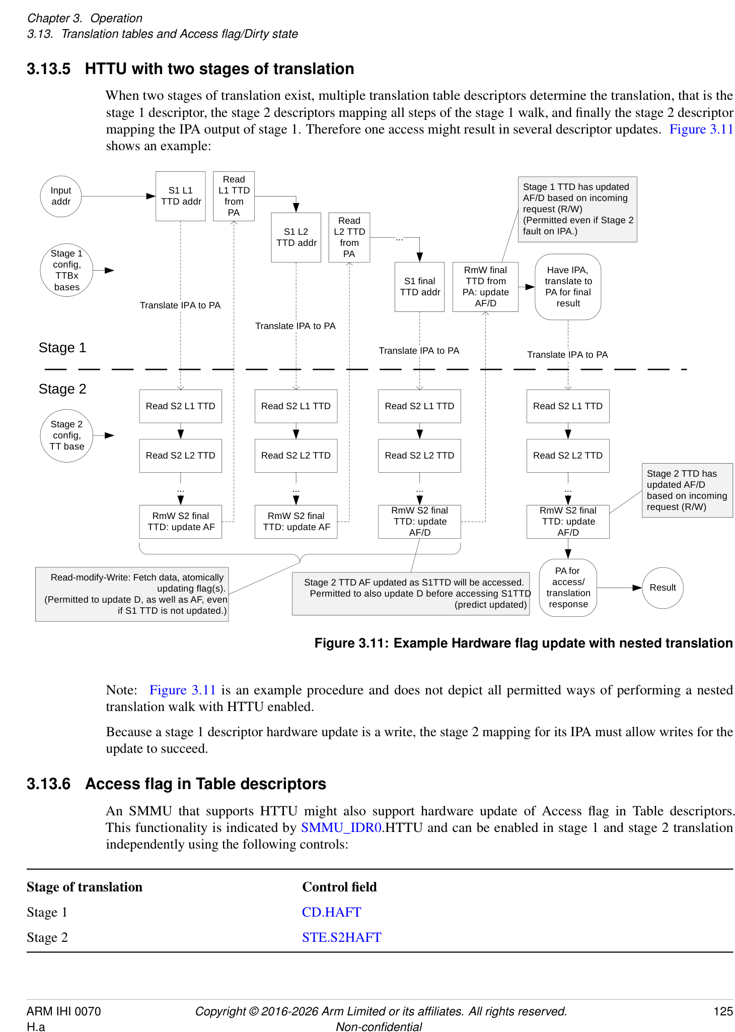
Read
Input  S1 L1  L1 TTD  Stage 1 TTD has updated
addr TTD addr from  AF/D based on incoming
PA request (R/W)
Read   (Permitted even if Stage 2
TTD addrS1 L2  L2 TTD from  ... fault on IPA.)
Stage 1  PA
config,  RmW final  Have IPA,
TTBx
S1 final  TTD from  translate to
bases
TTD addr PA: update  PA for final
Translate IPA to PA AF/D result
Translate IPA to PA
Stage 1 Translate IPA to PA Translate IPA to PA
Stage 2
Read S2 L1 TTD Read S2 L1 TTD Read S2 L1 TTD Read S2 L1 TTD
Stage 2
config,
TT base
Read S2 L2 TTD Read S2 L2 TTD Read S2 L2 TTD Read S2 L2 TTD
Stage 2 TTD has
... ... ... ... updated AF/D based on incoming
RmW S2 final  RmW S2 final  request (R/W)
RmW S2 final  RmW S2 final
TTD: update TTD: update
TTD: update AF TTD: update AF AF/D AF/D
PA for
Read-modify-Write: Fetch data, atomically updating flag(s). Stage 2 TTD AF updated as S1TTD will be accessed.Permitted to also update D before accessing S1TTD  translation access/ Result
(Permitted to update D, as well as AF, even
(predict updated)   response
if S1 TTD is not updated.)
Figure 3.11: Example Hardware flag update with nested translation
Note: Figure 3.11 is an example procedure and does not depict all permitted ways of performing a nested translation walk with HTTU enabled.
Because a stage 1 descriptor hardware update is a write, the stage 2 mapping for its IPA must allow writes for the update to succeed.
3.13.6 Access flag in Table descriptors
An SMMU that supports HTTU might also support hardware update of Access flag in Table descriptors. This functionality is indicated by SMMU_IDR0.HTTU and can be enabled in stage 1 and stage 2 translation independently using the following controls:
Stage of translation Control field Stage 1 CD.HAFT Stage 2 STE.S2HAFT
If hardware update of Access flag is disabled for a translation stage, then hardware update of Access flag in Table descriptors is also disabled.
The SMMU behaviors for hardware update of Access flag in Table descriptors are the same as in the PE architecture, including the following requirements:
-
When the Access flag in a Table descriptor must be updated.
-
When the Access flag in a Table descriptor is permitted to be updated.
-
If HAFT is enabled, then any Table entry with the Access flag clear is not permitted to be cached in a TLB.
-
The ordering requirements for hardware update of Access flag in a Table descriptor relative to hardware updates of other descriptors updated in the translation table walk, and the final access.
Hardware updates of Access flag in Table descriptors are made observable by completion of a CMD_SYNC in the same manner as hardware updates of the Access flag in page or block descriptors. See section 3.13.4 HTTU behavior summary .
Hardware updates of Access flag in Table descriptors are caused by ATS Translation Requests in the same manner as hardware updates of the Access flag in page or block descriptors. See section 3.13.7 ATS, PRI and translation table flag update .
3.13.7 ATS, PRI and translation table flag update
When ATS and PRI are used to support device access to dynamically paged memory, the Access state and the dirty state of the page need to be maintained. This section describes the SMMU page flag maintenance behavior in a system using ATS with PRI targeting dynamically paged memory.
Note: Maintenance of the Access flag and the dirty state of the page is primarily of importance to DMA to unpinned or paged memory, because use-cases with DMA to pinned memory would normally statically initialize page state.
3.13.7.1 Hardware flag update for ATS & PRI
Because the purpose of ATS is to cache translations outside the SMMU and to avoid subsequent translation interaction with the SMMU, if HTTU is enabled it is performed at the time of the ATS Translation Request (TR).
When an ATS TR is made, it must be assumed that a device will subsequently access the page. If the page is otherwise valid and an ATS response will be returned, AF is set to 1 in the descriptor in the same way as a direct transaction access through the SMMU.
In addition to the behavior that is described earlier in this section, if hardware-management of dirty state is enabled and an ATS request for write access (with NW == 0) is made to a page that is marked writable-clean, the SMMU assumes a write will be made to that page and marks the page as writable-dirty before returning the ATS response that grants write access. When this happens, the modification to the page data by a device is not visible before the page state is visible as writable-dirty. If HTTU is only enabled for Access, an ATS request for a write to a writable-clean or Read Only page results in an ATS Translation Completion with W == 0, and write access is denied.
If an ATS Translation Request is made for a write (NW == 0) to a nested translation configuration and the associated stage 1 translation is read-only (not writable), the dirty state is not updated in either of the stage 1 descriptor, or the stage 2 descriptor that is used to translate the output address from the stage 1 descriptor.
Note: This also applies if the stage 2 translation of the stage 1 output address is writable-clean.
When HTTU is enabled for stage 1 and stage 2 and Split-stage ATS is used (STE.EATS == 0b10), the ATS TR performs HTTU at stage 1, and updates for the stage 2 descriptors that are used to fetch and update the stage 1 descriptors are made. The following applies to the stage 2 descriptor for the final IPA:
-
The AF in the stage 2 descriptor for the final IPA is permitted to be speculatively set to 1 by the ATS TR.
-
If write permission is granted in the ATS Translation Completion, a writable-clean stage 2 descriptor for the final IPA is permitted to be marked as writable-dirty by the ATS TR.
-
3.13. Translation tables and Access flag/Dirty state
- When a subsequent Translated access to the IPA is translated, this choice does not affect the HTTU behavior of stage 2. - This choice does not affect the permissions that are returned in the Translation Completion, which reflect whether a write transaction is permitted by the combined permissions of both stages and treat a writable-clean stage 2 descriptor as writable. See section 13.6.3 _Split-stage (STE.EATS == 0b10) ATS behavior and responses_ .- The stage 2 translation of a subsequent Translated access marks the stage 2 descriptor as Accessed and might mark the descriptor as writable-dirty, provided that the ATS TR has not already performed this action.
3.13.7.2 Behavior with respect to flag maintenance for ATS & PRI without HTTU
If HTTU is not enabled for the Access flag, an ATS request to a page with AF == 0 and AFFD == 0 is denied. For this address a response granting R == W == 0, that is no access, is returned. The client device might then raise an error in a device-specific manner, or might issue a PRI page request, if supported and configured, to request that software makes the page available. Software can manually set AF == 1 on receipt of the PRI page request in anticipation of the device access.
An ATS request to any read-only page does not grant write access, that is it returns W == 0, if hardware update of dirty state of the page is not enabled. Read access might be granted in the response, if the conditions for the Access flag set out in this section are satisfied. The client device might raise an error in a device-specific manner, or might issue a PRI page request to request write access to the address. On receipt of a PRI request, software could assume that a request issued for write was initiated because data will shortly be written and mark the page writable-dirty before responding to the PRI request.
An ATS request for write to a page marked writable might grant write access, that is it returns W == 1 in the response. Software must consider writable pages as potentially dirty.
Note: PCIe PRI requests can be issued speculatively by an Endpoint. This implies speculatively marking the page as Dirty. This is not permitted by the Armv8-A architecture [4] and might be problematic for some software systems.
Because pages cannot speculatively be marked as Dirty, Arm recommends that a system designed for general-purpose software supports HTTU when PRI is used, so that the state of the page is marked Dirty only when a request for write access is made using ATS.
3.13.8 Hardware flag update for Cache Maintenance Operations and Destructive Reads
HTTU for Dirty state update is not performed for the following operations:
-
Invalidate Cache Maintenance Operations.
-
Destructive Reads.
-
Destrutive Hints.
See also:
-
16.7.2.2 Permissions model for Cache Maintenance Operations
-
3.22.2 Permissions model
When these operations are performed to a writable-clean translation table descriptor, the descriptor is not updated to be writable-dirty. If the required Read or Execute permissions are available, but the descriptor is not writable-dirty, the operations are downgraded as described in the corresponding section.
This rule does not affect HTTU of the Access flag, which occurs if required. In this case, an update to the Dirty state of the stage 2 descriptor that translates the stage 1 table is performed.
Note: For the purposes of determining execute permission, a writable-clean descriptor is considered to be writable when HTTU is enabled, which is consistent with the Armv8-A architecture. As described in this section, this principle applies even when the descriptor is not updated to writable-dirty for an Invalidate, DR or DH.
3.13.9 Hardware Dirty state tracking Structure
This section applies only when SMMU_IDR3.HDBSS is 1.
The Hardware Dirty state tracking structure (HDBSS) provides an enhanced method for tracking the Dirty state of translation table descriptors in a compacted format.
An HDBSS comprises of two HDBSS tables and is defined by the following registers:
-
SMMU_(*_)HDBSS_BASE0.
-
SMMU_(*_)HDBSS_PROD0.
-
SMMU_(*_)HDBSS_BASE1.
-
SMMU_(*_)HDBSS_PROD1.
Figure 3.12 shows a visual representation of the HDBSS tables.
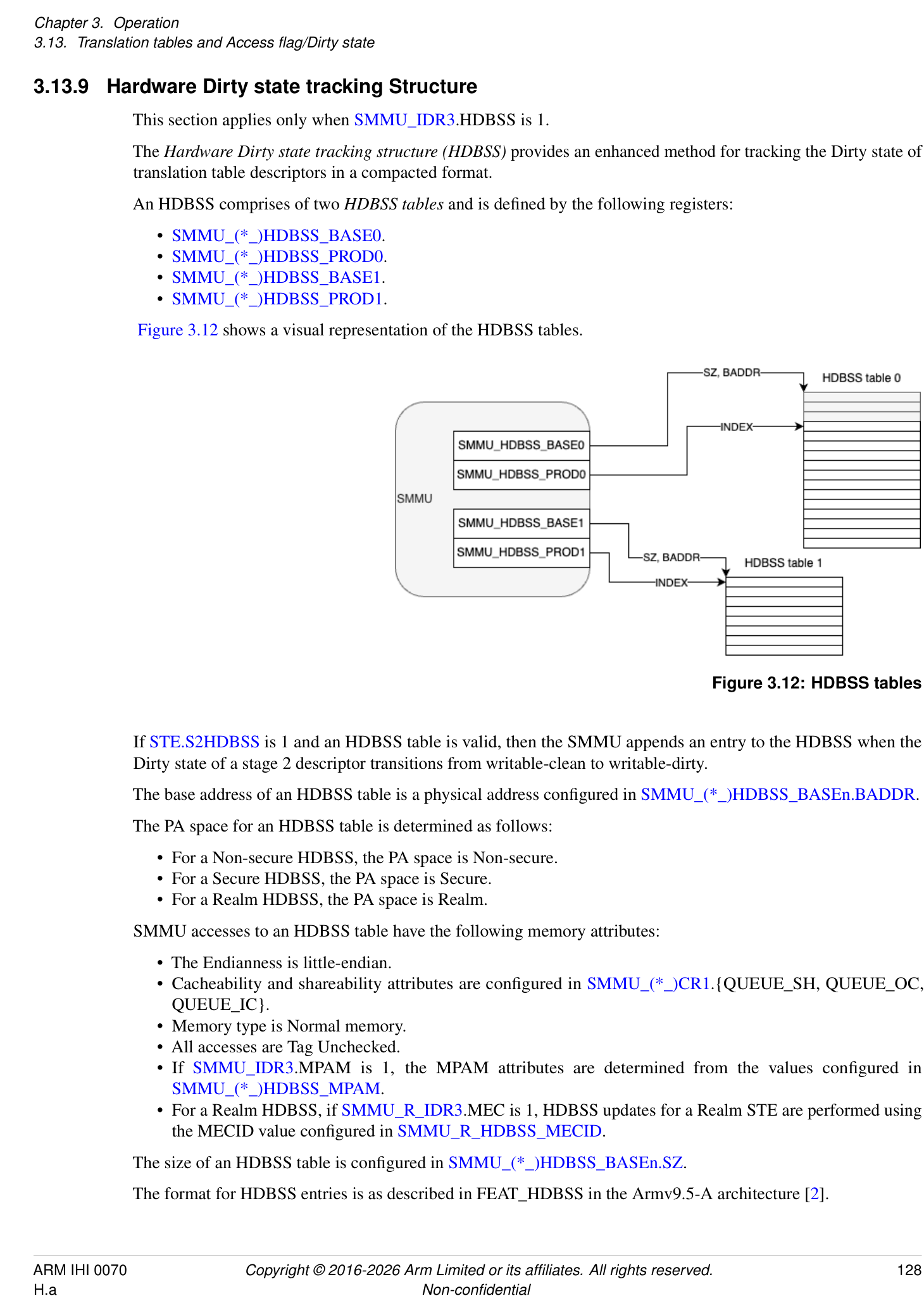
Figure 3.12: HDBSS tables
If STE.S2HDBSS is 1 and an HDBSS table is valid, then the SMMU appends an entry to the HDBSS when the Dirty state of a stage 2 descriptor transitions from writable-clean to writable-dirty.
The base address of an HDBSS table is a physical address configured in SMMU_(*_)HDBSS_BASEn.BADDR.
The PA space for an HDBSS table is determined as follows:
-
For a Non-secure HDBSS, the PA space is Non-secure.
-
For a Secure HDBSS, the PA space is Secure.
-
For a Realm HDBSS, the PA space is Realm.
SMMU accesses to an HDBSS table have the following memory attributes:
-
The Endianness is little-endian.
-
Cacheability and shareability attributes are configured in SMMU_(*_)CR1.{QUEUE_SH, QUEUE_OC, QUEUE_IC}.
-
Memory type is Normal memory.
-
All accesses are Tag Unchecked.
-
If SMMU_IDR3.MPAM is 1, the MPAM attributes are determined from the values configured in SMMU_(*_)HDBSS_MPAM.
-
For a Realm HDBSS, if SMMU_R_IDR3.MEC is 1, HDBSS updates for a Realm STE are performed using the MECID value configured in SMMU_R_HDBSS_MECID.
The size of an HDBSS table is configured in SMMU_(*_)HDBSS_BASEn.SZ.
The format for HDBSS entries is as described in FEAT_HDBSS in the Armv9.5-A architecture [2].
3.13.9.1 HDBSS Table updates
While performing Dirty state tracking, the SMMU appends entries to one of the two HDBSS tables as described below:
-
When a transaction triggers an HDBSS update and the HDBSS is not halted, the SMMU appends entries to HDBSS table 1 if either of the following are true:
-
HDBSS table 0 is invalid.
-
HDBSS table 0 is full.
-
-
Otherwise, the SMMU appends entries to HDBSS table 0.
Note: For more information on halting the HDBSS, see 3.13.9.5 HDBSS Errors .
The SMMU can only append entries to a single HDBSS table at a time.
The rules for appending entries to an HDBSS table are the same as those described in FEAT_HDBSS in the Armv9.5-A architecture [2], using SMMU_(*_)HDBSS_PRODn.INDEX.
The single-copy atomicity size of HDBSS updates is at least 64-bit.
An HDBSS table is full when SMMU_()HDBSS_PRODn.INDEX is greater than or equal to 2[(][SMMU()HDBSS_BASEn.SZ][+12)] /8. For normal hardware behavior, this is indicated by SMMU(*_)HDBSS_PRODn.INDEX[SMMU_HDBSS_BASEn.SZ+9] being set to 1.
When an HDBSS table becomes full, an interrupt is generated. See section 3.18.2 Interrupt sources .
If an update to SMMU_()HDBSS_PRODn.INDEX becomes observable, then all updates to the HDBSS table up to that index value are also observable. This means that when an HDBSS write becomes visible to the rest of the Shareability domain, the SMMU permits the corresponding update to SMMU(_)HDBSS_PRODn.INDEX to be observed.
If an HDBSS table update is observable, then a corresponding HTTU update is guaranteed to be observable by the completion of a CMD_SYNC.
The SMMU is permitted to set any HDBSS entries that are ahead of SMMU_(*_)HDBSS_PRODn.INDEX to zero.
If SMMU_ROOT_IDR0.ROOT_IMPL is 1 and SMMU_ROOT_CR0.GPCEN is 1, then accesses to an HDBSS are subject to Granule Protection Checks. See 3.25 Granule Protection Checks .
There is no ordering guarantee between two updates and atomicity might be lost in the following cases:
-
The HDBSS and the translation table entry to be updated reside at the same location.
-
The write to an HDBSS and the write access being translated target the same location.
No architected PMCG events count accesses to an HDBSS.
Note: HTTU updates are captured in PMCG events in the same manner as described in 10.3 Monitor events .
3.13.9.2 HDBSS Table Validity
An HDBSS table is valid if both of the following are true:
-
SMMU_(*_)HDBSS_BASEn.V == 1.
-
SMMU_(*_)HDBSS_PRODn.VACK == 1.
If software programs SMMU_()HDBSS_BASEn.V to 0, an HDBSS table is considered valid until the Update completes, that is until the SMMU sets SMMU(_)HDBSS_PRODn.VACK to 0.
An HDBSS table is invalid if both of the following are true:
-
SMMU_(*_)HDBSS_BASEn.V == 0.
-
SMMU_(*_)HDBSS_PRODn.VACK == 0.
If software programs SMMU_()HDBSS_BASEn.V to 1, an HDBSS table is considered invalid until the Update completes, that is until the SMMU sets SMMU(_)HDBSS_PRODn.VACK to 1.
It is a programming error to update the STE.S2HDBSS field from 0 to 1 when both SMMU_()HDBSS_BASEn.V fields are 0. However, software is permitted to update one of the SMMU(_)HDBSS_BASEn.V fields from 1 to 0 during Dirty state tracking.
If an HDBSS table is invalid, the SMMU does not perform any accesses, including speculative read accesses, to the memory region configured by the following fields:
-
SMMU_(*_)HDBSS_BASEn.SZ.
-
SMMU_(*_)HDBSS_BASEn.BADDR.
3.13.9.3 HDBSS Initialization Procedure
To initialize an HDBSS, software is required to perform the following sequence:
-
Program both of the SMMU_(*_)HDBSS_PRODn fields to 0. This ensures the index of each HDBSS points to the beginning of the structure, and that the error status field is cleared.
-
Program both of the SMMU_(*_)HDBSS_BASEn fields with a base address and size.
-
Program both of the SMMU_()HDBSS_BASEn.V fields to 1 to indicate to the SMMU that the HDBSS tables are available for use. This step completes when the SMMU sets both of the SMMU(_)HDBSS_PRODn.VACK fields to 1.
-
Program the STE.S2HDBSS field to 1 for the STEs of the devices associated with the VM being migrated, and issue appropriate CMD_CFGI_* commands to ensure that the new configuration is in use.
3.13.9.4 HDBSS Processing Procedure
To process an HDBSS, software is expected to perform the following sequence:
-
Program the SMMU_()HDBSS_BASE0.V field to 0. This step completes when the SMMU sets the SMMU(_)HDBSS_PROD0.VACK field to 0. This guarantees that all outstanding updates have completed. An interrupt resulting from the HDBSS table becoming full must be ignored.
-
Share the location of the contents of the HDBSS table with the agent responsible for cleaning the stage 2 descriptors.
-
Either allocate a new and empty HDBSS table, or copy the contents and zero the current HDBSS table. 4. Program the SMMU_(*_)HDBSS_PROD0.INDEX field to zero.
-
Program the SMMU_(*_)HDBSS_BASE0.V field to 1, advertising that the HDBSS table 0 is available for use.
-
Wait until the SMMU_(*_)HDBSS_PROD0.VACK field is 1.
-
At this point, the SMMU has switched to using HDBSS table 0.
-
Repeat steps 1-6 for HDBSS table 1.
3.13.9.5 HDBSS Errors
If the SMMU encounters an error while attempting to append an entry to an HDBSS table, it updates both of the following fields:
-
SMMU_(*_)HDBSS_PRODn.ERR.
-
SMMU_(*_)HDBSS_PRODn.ERR_REASON.
Dirty state tracking stops when the value of SMMU_()HDBSS_PRODn.ERR is not the same as the value of SMMU(_)HDBSS_BASEn.ERRACK.
The HDBSS is considered to be halted if any of the following conditions are true:
-
Both HDBSS tables are full.
-
SMMU_(*_)HDBSS_BASE1.V is 0 and HDBSS table 0 is full.
-
SMMU_(*_)HDBSS_BASE0.V is 0 and HDBSS table 1 is full.
-
Both of the SMMU_(*_)HDBSS_BASEn.V fields are 0.
If the HDBSS is halted and a transaction triggers an HDBSS update, all of the following apply:
-
The value of SMMU_(*_)HDBSS_PROD1.ERR is toggled.
-
The SMMU_(*_)HDBSS_PROD1.ERR_REASON field is set to 0b11.
-
No entry is appended to the HDBSS table.
If SMMU_ROOT_IDR0.ROOT_IMPL is 1, SMMU_ROOT_CR0.GPCEN is 1, and an access to the HDBSS generates a GPC fault, all of the following apply:
-
The value of SMMU_(*_)HDBSS_PRODn.ERR is toggled.
-
SMMU_(*_)HDBSS_PRODn.ERR_REASON is set to 0b10.
-
SMMU_(*_)HDBSS_PRODn.INDEX points to the entry that generated the fault.
-
The SMMU handles the fault as a GPC fault on an SMMU-originated access. See 3.25.3 SMMU-originated accesses .
When an external abort occurs on an HDBSS write, all of the following apply:
-
The value of SMMU_(*_)HDBSS_PRODn.ERR is toggled.
-
SMMU_(*_)HDBSS_PRODn.ERR_REASON is set to 0b01.
-
SMMU_(*_)HDBSS_PRODn.INDEX points to the entry that generated the fault.
Note: n is the index of the HDBSS table that would have been updated if the error condition had not occurred. If the error condition is due to a halted HDBSS, n is always 1.
When the value of SMMU_()HDBSS_PRODn.ERR is toggled, if SMMU()GERRORN.HDBSS_ERR does not already indicate an active error, the SMMU activates SMMU()GERROR.HDBSS_ERR. If an error is observable in SMMU(_)GERROR.HDBSS_ERR, then at least one of the conditions described above has been made observable.
Note: An HDBSS error does not cause a transaction to be aborted.
Note: The error behavior specified by this feature diverges from the Arm A-profile architecture in that stage 2 dirty state hardware update is not prevented when an HDBSS error has been encountered.
If software inappropriately configures the value of SMMU_()HDBSS_BASEn.ERRACK to mismatch the value of SMMU()HDBSS_PRODn.ERR, it is CONSTRAINED UNPREDICTABLE whether the SMMU records a dirty state update to the HDBSS table or whether a subsequent error is correctly reported. This CONSTRAINED UNPREDICTABLE behavior also applies when software transitions an HDBSS table from invalid to valid while the value of SMMU()HDBSS_BASEn.ERRACK is not the same as the value of SMMU(_)HDBSS_PRODn.ERR.
3.13.9.6 HDBSS Restoration Procedure
To restore operation of the HDBSS following any error, EL2 software must perform the following steps (steps 2-5 may be performed in any order):
-
Program both of the SMMU_(*_)HDBSS_BASEn.V fields to 0.
-
Acknowledge the error by updating the value of SMMU_(*_)GERRORN.HDBSS_ERR.
-
Program the values of SMMU_()HDBSS_PRODn.ERR and SMMU(_)HDBSS_BASEn.ERRACK so that they are consistent.
-
Either allocate a new, empty HDBSS table or zero the current table. This applies to the table affected by the error (in the case of a GPC fault or external abort) or to both tables in the HDBSS-halted scenario.
-
Program both of the SMMU_(*_)HDBSS_PRODn fields to 0.
-
Program both of the SMMU_(*_)HDBSS_BASEn.V fields to 1.
3.13.10 Hardware Accelerator for Cleaning Dirty State
This section applies only when SMMU_IDR3.HACDBS is 1.
The Hardware Accelerator for Cleaning Dirty State (HACDBS) provides an enhanced method for updating page descriptors from writable-dirty to writable-clean.
The HACDBS is a structure, similar to an HDBSS, that is generated by either the SMMU or a PE during live migration.
Figure 3.13 shows a visual representation of the HACDBS.
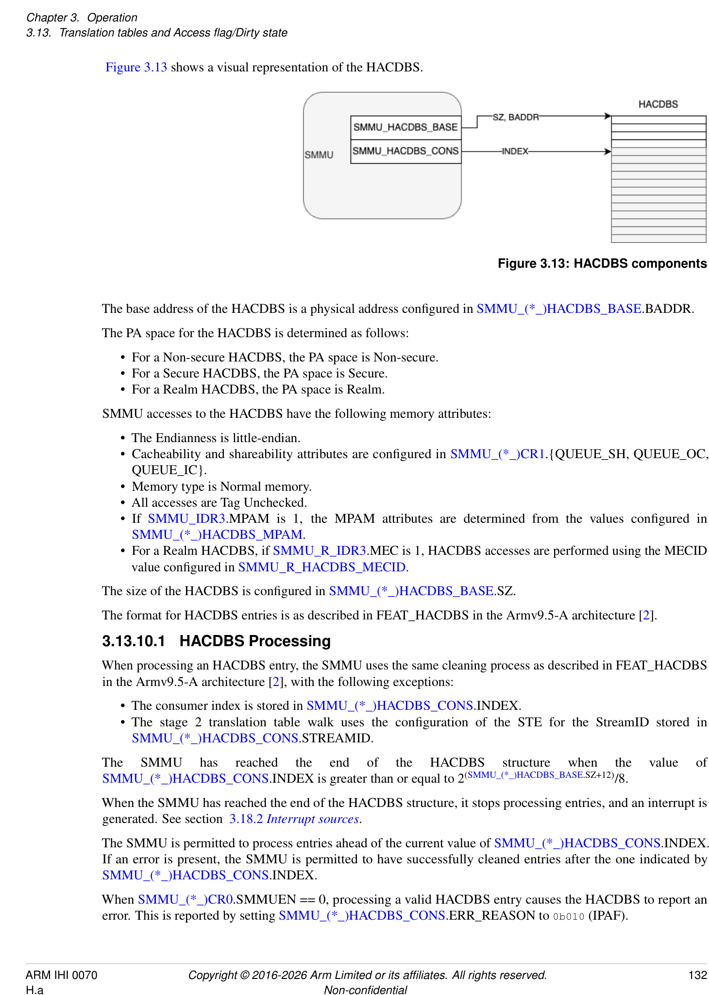
Figure 3.13: HACDBS components
The base address of the HACDBS is a physical address configured in SMMU_(*_)HACDBS_BASE.BADDR.
The PA space for the HACDBS is determined as follows:
-
For a Non-secure HACDBS, the PA space is Non-secure.
-
For a Secure HACDBS, the PA space is Secure.
-
For a Realm HACDBS, the PA space is Realm.
SMMU accesses to the HACDBS have the following memory attributes:
-
The Endianness is little-endian.
-
Cacheability and shareability attributes are configured in SMMU_(*_)CR1.{QUEUE_SH, QUEUE_OC, QUEUE_IC}.
-
Memory type is Normal memory.
-
All accesses are Tag Unchecked.
-
If SMMU_IDR3.MPAM is 1, the MPAM attributes are determined from the values configured in SMMU_(*_)HACDBS_MPAM.
-
For a Realm HACDBS, if SMMU_R_IDR3.MEC is 1, HACDBS accesses are performed using the MECID value configured in SMMU_R_HACDBS_MECID.
The size of the HACDBS is configured in SMMU_(*_)HACDBS_BASE.SZ.
The format for HACDBS entries is as described in FEAT_HACDBS in the Armv9.5-A architecture [2].
3.13.10.1 HACDBS Processing
When processing an HACDBS entry, the SMMU uses the same cleaning process as described in FEAT_HACDBS in the Armv9.5-A architecture [2], with the following exceptions:
-
The consumer index is stored in SMMU_(*_)HACDBS_CONS.INDEX.
-
The stage 2 translation table walk uses the configuration of the STE for the StreamID stored in SMMU_(*_)HACDBS_CONS.STREAMID.
The SMMU has reached the end of the HACDBS structure when the value of SMMU_()HACDBS_CONS.INDEX is greater than or equal to 2[(][SMMU(_)HACDBS_BASE][.SZ+12)] /8.
When the SMMU has reached the end of the HACDBS structure, it stops processing entries, and an interrupt is generated. See section 3.18.2 Interrupt sources .
The SMMU is permitted to process entries ahead of the current value of SMMU_()HACDBS_CONS.INDEX. If an error is present, the SMMU is permitted to have successfully cleaned entries after the one indicated by SMMU(_)HACDBS_CONS.INDEX.
When SMMU_()CR0.SMMUEN == 0, processing a valid HACDBS entry causes the HACDBS to report an error. This is reported by setting SMMU(_)HACDBS_CONS.ERR_REASON to 0b010 (IPAF).
The effect of stage 2 permissions on how entries are processed by the SMMU is the same as described in FEAT_HACDBS in the Armv9.5-A architecture [2], with the following exceptions:
-
The index that is incremented is the consumer index stored in SMMU_(*_)HACDBS_CONS.INDEX.
-
Faults caused by the stage 2 descriptor having permissions other than writable-clean or writable-dirty are reported by setting SMMU_(*_)HACDBS_CONS.ERR_REASON to 0b011 (IPAHACF).
For the purpose of cleaning descriptors using this feature, STE.S2HD is treated as 1. As described in FEAT_HACDBS in the Armv9.5-A architecture [2], this also means that, for a descriptor to be qualified as writable-clean or writable-dirty in this context, it is not required that the dirty-state hardware update be enabled at stage 2.
If SMMU_ROOT_IDR0.ROOT_IMPL is 1 and SMMU_ROOT_CR0.GPCEN is 1, then accesses to the HACDBS are subject to Granule Protection Checks. See 3.25 Granule Protection Checks .
Translations and accesses required to clean stage 2 descriptors are captured in PMCG events in the same manner as described in 10.3 Monitor events . This means that Event IDs 1 to 5 can be counted as part of HACDBS processing.
Note : Consistent with the A-profile architecture[2], accesses to the HACDBS are not counted.
3.13.10.2 HACDBS States
The HACDBS is enabled if both of the following are true:
-
SMMU_(*_)HACDBS_BASE.EN == 1.
-
SMMU_(*_)HACDBS_CONS.ENACK == 1.
If software programs SMMU_()HACDBS_BASE.EN to 1, the HACDBS is considered to be disabled until the Update completes, that is until the SMMU sets SMMU(_)HACDBS_CONS.ENACK to 1.
The HACDBS is disabled if both of the following are true:
-
SMMU_(*_)HACDBS_BASE.EN == 0.
-
SMMU_(*_)HACDBS_CONS.ENACK == 0.
If software programs SMMU_()HACDBS_BASE.EN to 0, the HACDBS is considered to be enabled until the Update completes, that is until the SMMU sets SMMU(_)HACDBS_CONS.ENACK to 0.
When software updates SMMU_()HACDBS_BASE.EN from 1 to 0, by also updating SMMU(_)HACDBS_CONS.ENACK, the SMMU guarantees all of the following:
-
All outstanding walks, including updates of descriptors from writable-dirty to writable-clean, have completed.
-
All entries up to and including SMMU_(*_)HACDBS_CONS.INDEX - 1 have been successfully processed.
-
In the case of an error, SMMU_()HACDBS_CONS.INDEX points to the earliest entry that generated an error, and the values of the SMMU(_)HACDBS_CONS.{ERR_REASON, ERR} fields are updated.
-
• No errors will be reported later.
Completion of an Update of SMMU_()CR0.SMMUEN from 1 to 0 guarantees that HACDBS translation requests and updates of descriptors from writable-dirty to writable-clean have completed. Any resulting errors are not guaranteed to be observed until completion of an Update of SMMU(_)HACDBS_BASE.EN from 1 to 0.
3.13.10.3 HACDBS Errors
All errors described in FEAT_HACDBS in the Armv9.5-A architecture [2] apply to the HACDBS in the SMMU.
Note: The bit encodings in SMMU_(*_)HACDBS_CONS.ERR_REASON do not match the ones defined by FEAT_HACDBS in the Armv9.5-A architecture [2], however, the order and descriptions are the same.
If the SMMU encounters an error while processing the HACDBS, it updates both of the following fields:
-
SMMU_(*_)HACDBS_CONS.ERR.
-
SMMU_(*_)HACDBS_CONS.ERR_REASON.
When an error occurs, SMMU_(*_)HACDBS_CONS.INDEX has the same behavior as HACDBSCONS_EL2.INDEX as described by FEAT_HACDBS in the Armv9.5-A architecture [2].
The SMMU handles a GPC fault on an access to the HACDBS as a GPC fault on an SMMU-originated access. See 3.25.3 SMMU-originated accesses .
When there is an error related to the STE pointed to by SMMU_()HACDBS_CONS.STREAMID or when STE.Config != 0b11x, this is reported by setting SMMU(_)HACDBS_CONS.ERR_REASON == 0b100 (STEF).
The following table provides an overview of how HACDBS errors are reported:
| …the error reported in | |
|---|---|
| If HACDBS encounters an… | SMMU_(*_)HACDBS_CONS.ERR_REASON is |
| Abort on HACDBS read | STRUCTF |
| Fetch of HACDBS from unsupported memory type | STRUCTF |
| GPF or GPT lookup error during access to the HACDBS | STRUCTF |
| table | |
| F_STE_FETCH, C_BAD_STREAMID, C_BAD_STE | STEF |
| F_VMS_FETCH, F_CD_FETCH, C_BAD_CD | STEF |
| STE with stage 2 not confgured | STEF |
| GPF or GPT lookup error during access to the STE | STEF |
| F_ADDR_SIZE, F_TRANSLATION, or F_WALK_EABT | IPAF |
| External abort on the update of descriptor | IPAF |
| GPF or GPT lookup error during access to the translation | IPAF |
| tables | |
| SMMU_(*_)CR0.SMMUEN == 0 | IPAF |
| Errors that would report IPAHACF in FEAT_HACDBS | IPAHACF |
The SMMU does not record any event in the Event queue for HACDBS errors.
When the value of SMMU_()HACDBS_CONS.ERR is toggled, if SMMU()GERRORN.HACDBS_ERR does not already indicate an active error, the SMMU activates SMMU()GERROR.HACDBS_ERR. If an error is observable in SMMU()GERROR.HACDBS_ERR, then it has already been made observable in SMMU(*_)HACDBS_CONS.{ERR, ERR_REASON}.
If the value of SMMU_()HACDBS_CONS.ERR does not match the value of SMMU(_)HACDBS_BASE.ERRACK, then all of the following apply:
-
The SMMU stops processing entries from the HACDBS.
-
The error is reported in SMMU_(*_)GERROR.HACDBS_ERR. This raises an interrupt to the PE.
If there is an error during processing of an HACDBS entry, software is expected to program SMMU_()HACDBS_BASE.EN to 0. When the SMMU sets SMMU(_)HACDBS_CONS.ENACK to 0, it is guaranteed that all outstanding fetches of HACDBS entries, stage 2 walks and the update of descriptors from writable-dirty to writable-clean have completed.
If software inappropriately configures the value of SMMU_()HACDBS_BASE.ERRACK to mismatch the value of SMMU()HACDBS_CONS.ERR, it is CONSTRAINED UNPREDICTABLE whether the SMMU continues processing the HACDBS or whether a subsequent error is correctly reported. This CONSTRAINED UNPREDICTABLE behavior also applies when software transitions the HACDBS from disabled to enabled while the value of SMMU()HACDBS_BASE.ERRACK is not the same as the value of SMMU(_)HACDBS_CONS.ERR.
3.14 Speculative accesses
An implementation might allow incoming transactions to be marked as speculative in an IMPLEMENTATION DEFINED manner. Only read transactions are allowed to be marked as speculative. The behavior of a write transaction that is marked as speculative is always to terminate the transaction with an abort, and no event is recorded to software.
The behavior of a read transaction that is marked as speculative depends on two things:
-
If the translation occurs successfully without faulting, the read transaction continues into the system and returns data. Otherwise if any kind of fault or configuration error occurs, the transaction is terminated with an abort; no event is recorded to software for any speculative transaction. The determination of a fault is no different from non-speculative read transactions, including Access flag faults.
-
If HTTU is enabled and translation succeeds without fault, the read transaction updates the Access flags of relevant translation table descriptors.
The SMMU HTTU rules match those set out for Armv8.1-A [2], with respect to hardware update of Access flag and dirty state, including update of stage 2 translation table flags for both speculative accesses made at stage 1 and writes of stage 1 descriptors due to the setting of Access flags.
An implementation might provide translation services to a client device, and might support speculatively-issued Translation Requests. An IMPLEMENTATION DEFINED mechanism must be used to differentiate speculative Translation Requests from non-speculative Translation Requests.
Note: This mechanism might arise as an IMPLEMENTATION SPECIFIC service provided to another device. PCIe ATS Translation Requests are always non-speculative.
If a received Translation Request is marked as speculative, behavior is dependent on the read/write property of the request:
-
Translation Requests for an address to be written grant write in the response only if the translation table descriptors that translate the address are all marked writable-dirty. In this case, if hardware management of the Access flag is enabled, the request updates AF. If hardware management of dirty state is enabled, speculative Write Translation Requests do not mark any writable-clean descriptor in the first or only stage of translation as writable-dirty. If the descriptor is marked writable-clean, the response does not grant write access.
-
Translation Requests for an address to be read return a successful response, if appropriate, and if hardware management of the Access flag is enabled updates AF.
-
In both cases, if hardware management of Access flag and dirty state is enabled in a nested translation then an update of a stage 1 descriptor to set AF or the Dirty state of the page might cause the stage 2 descriptors related to the updated stage 1 descriptor to be marked as Dirty as required.
The response to a Translation Request indicates whether a translation request was denied because of a page fault or otherwise missing translation, or whether a valid translation existed but the request failed because the translation was writable-clean.
Note: A device might use this information to determine whether to stop making requests or whether to subsequently try again with a non-speculative write.
For speculative accesses of SMMU structures and translations, see section 3.21.1 Translation tables and TLB invalidation completion behavior and 3.21.3 Configuration structures and configuration invalidation completion .
3.15 Coherency considerations and memory access types
Arm anticipates that the SMMU will access all in-memory structures and queues in a manner that does not require software cache maintenance of the PE caches. Arm expects that this be IO-coherent access to normal shared memory, but in implementations that cannot support cache coherency, this might be non-cached access. Some Embedded Implementations might require use of memory mapped addresses as non-cached by the PEs, see section 3.16 Embedded Implementations below. The degree to which the different memory access types and attributes are supported is IMPLEMENTATION DEFINED.
All in-memory structures and queues are accessed using Normal memory types. Configuration fields exist for Stream table, Context Descriptor and translation table fetches to govern Cacheability and Shareability of such accesses. MSI writes can be configured to make Device-type accesses.
If hardware update of the Access flag or the dirty state of a page is supported, atomic access is required to update translation tables that are shared between the PE and SMMU. Support for atomic access using local monitors requires a fully-coherent interconnect port.
If the memory system supports Armv8.1 [2] atomic operations, the SMMU might support atomic updates without local monitors, and not require a fully-coherent port. Because different SMMU implementations might use different mechanisms for atomic update of the flags, and because local monitors require coherent cacheable access, behavior is IMPLEMENTATION DEFINED if hardware flag updates are enabled on translation tables configured to be accessed as Non-cacheable.
To limit complexity, the SMMU might respond to snoops from the system only as much as required for atomic updates to translation tables with local monitors, if required. This means that all other memory access by the SMMU might be IO-coherent. That is, SMMU configuration caches are not required to be snooped by PE accesses. When configuration data structures are changed, software is required to issue invalidation commands to the SMMU.
The SMMU respects the same single-copy atomicity rules as PEs regarding 64-bit translation table descriptor accesses, or 128-bit translation table descriptor accesses if VMSAv9-128 is in use.
When configured by software, that is when not fixed in Embedded Implementations, Arm recommends that the in-memory data structures and queues are treated as Normal memory cached by the PE when the SMMU implementation is able to access them IO-coherently.
Note: This might be useful to avoid explicit cache maintenance on the PE side. When an SMMU is not able to make IO-coherent access, a similar programming model might be achieved using normal non-cached mappings from the PE.
Note: The configuration structure invalidation commands might be used by a hypervisor to maintain coherency between guest and shadow structures that it might use.
When a system supports IO-coherent accesses from the SMMU for access to configuration structures, translation tables, queues and CMD_SYNC, GERROR, Event queue and PRI queue MSIs, this is presented to software using SMMU_IDR0.COHACC == 1. If a system does not support IO-coherent access from the SMMU, SMMU_IDR0.COHACC must be 0.
3.15.1 Client devices
SMMU translation is supported for Cache maintenance operations sent from client devices into the system. TLB-maintenance operations sent from client devices into the system are not permitted and are never propagated by the SMMU.
SMMU clients might contain caches that are fully-coherent with the rest of the system. Fully-coherent traffic uses physical addresses for both memory and snoop requests on either direction. For example, client access to the cache and writebacks from the cache might use addresses that were obtained from the SMMU using ATS or obtained from a TLB in the client that is filled from the SMMU. The latter case might arise where an SMMU is implemented as part of a complex device.
Devices might contain caches that do not support hardware coherency and which might be filled using non-physical addresses through an SMMU.
In distributed systems, different client devices might have different paths through the SMMU into the system, and these can differ in their ability to perform IO-coherent access. These paths might also differ from those used by the SMMU for its own configuration access, hence SMMU_IDR0.COHACC does not indicate whether client devices can also make IO-coherent accesses. Arm recommends that whether a given client device is capable of performing IO-coherent access is described to system software in a system-specific manner.
3.15.1.1 Fully-coherent client devices
For a fully-coherent SMMU client the following behaviors apply:
-
Granule protection checks (GPC) apply to fully-coherent requests.
-
DPT checks apply to fully-coherent requests, with the following exception:
- The DPT W bit is permitted to be treated as 1 for a fully-coherent client, where this is required by the coherency protocol.
-
Client-originated snoop requests bypass the SMMU and are not subject to DPT checks or GPC. Such requests might be terminated by a system-specific policy.
- Note: The forwarding of snoop requests from the system to an SMMU fully-coherent client is IMPLEMENTATION DEFINED and must meet the security requirements of the system.
-
A fully-coherent SMMU client is permitted to be either a StreamID client or a NoStreamID client.
Related definitions in this context:
-
A client-originated fully-coherent request allows a cache line to be allocated into a coherent cache in an SMMU client, or relates to a previously allocated cache line.
-
A client-originated snoop request allows retrieving cache line data and/or modifying cache line state at a coherent cache, for cache lines that are managed by a home agent in an SMMU client.
- Note: An SMMU client device might include a home agent in cases where the device is the backing store for memory that is coherently accessible to observers in the system.
3.16 Embedded Implementations
Some implementations might support the use of on-chip or internal storage for one or more of the Stream table structures, the Command queue, or the Event queue. This manifests itself as register base pointers and properties that are hard-wired to point to the on-chip storage. Such queues and structures are of a fixed size and configuration and in all cases are discoverable by system software. Software must not assume that it is necessary to allocate tables in RAM and set up pointers. It must initially probe for an existing configuration. SMMU_IDR1.TABLES_PRESET and SMMU_IDR1.QUEUES_PRESET indicate that the Stream table base address and queue base addresses are hardwired to indicate pre-existing storage for the tables or queues, or both. When SMMU_IDR1.REL is set, the base addresses are given relative to the start of the SMMU register memory map, rather than as absolute addresses.
An implementation using internal storage for configuration and queues is not required to access this storage through the coherency domain of the PEs. Data accesses from the PE require manual cache maintenance or use of a non-cached memory type for these addresses.
For an implementation using internal storage for configuration and queues, it is required that all address regions for those configuration structures and queues do not overlap. This requirement applies both within the same physical address space, and across Non-secure and Secure PA spaces.
3.16.1 Changes to structure and queue storage behavior when fixed/preset
Non-preset tables/queues are stored in normal memory. When an Embedded Implementation (EI) contains a preset structure or queue in internal storage it is not required that all bits of all structures/queue entries are accessible exactly as they would be in normal memory. For example, an implementation might not provide storage for fields in structures and queues that would not be used by architected behavior.
3.16.1.1 Event Queue and PRI Queue
All entries in an embedded Event queue or PRI queue, that is where SMMU_IDR1.QUEUES_PRESET == 1, are permitted to have read-only/write-ignored behavior with respect to software accesses.
3.16.1.2 Command Queue
Entries in an embedded Command queue, that is where SMMU_IDR1.QUEUES_PRESET == 1, are readable and writable, but are not required to provide storage outside of the union of all defined fields for all implemented commands. In addition, referring to the Command encodings in Chapter 4 Commands , storage is not required to be provided for:
-
Reserved and undefined fields.
-
High-order bits of StreamID fields beyond the implemented range of StreamIDs.
-
High-order bits of SubstreamID fields beyond the implemented range of SubstreamIDs (including the entire field if SubstreamIDs are not implemented).
-
SSV fields, if SubstreamIDs are not implemented.
-
STAG bits that are always generated as ‘0’ to software.
Note: An implementation might choose to use fewer than 16 bits of STAG when communicating stalled faults to software.
-
SSec, if only Non-secure state is supported.
-
CMD_SYNC MSIData, MSIAddress and MSIWriteAttributes if MSIs are not supported by the Security state of the Command queue.
-
ASID[15:8] if SMMU_IDR0.ASID16 == 0, or VMID[15:8] if SMMU_IDR0.VMID16 == 0.
-
CMD_CFGI_STE Leaf parameter (embedded Stream tables are single-level).
-
Fields in any command type that gives rise to CERROR_ILL.
A bit that is not stored due to these rules has RAZ/WI behavior.
Note: An implementation determines the set of required storage bits from IMPLEMENTATION SPECIFIC configuration options and values.
Software must not assume that it can write an arbitrary 16-byte sequence to a Command queue entry and read back the sequence unmodified. However, functional fields that form valid command parameters must be readable by software for debug and read-modify-write construction of commands (the queue is not considered write-only).
3.16.1.3 Stream Table Entry
Entries in an embedded Stream table are freely read/write accessible, but storage is not required to be provided for:
-
Undefined fields.
-
Reserved/ RES0 fields.
-
Fields that are IGNORED in all possible configurations that an implementation supports.
-
Fields permitted to have RAZ/WI behavior.
As an example, storage is not required for STE.S1ContextPtr on an SMMU that has an embedded Stream table but does not support stage 1.
Note: Fields Reserved for software use do not alter SMMU function but must be stored in their entirety.
3.17 TLB tagging, VMIDs, ASIDs and participation in broadcast TLB maintenance
Cached translations within the SMMU are tagged with:
-
A translation regime, given by the STE’s StreamWorld and derived in part from STE.STRW. This applies to all cached translations.
-
An ASID, if the translation regime supports ASIDs.
-
A VMID, if stage 2 is implemented by the SMMU and if the translation regime supports VMIDs.
This is summarized in the table below:
| StreamWorld Address Type | Tags |
|---|---|
| ASID ASET VMID | |
| NS-EL1 VA | Yes, if TTD.nG == 1 Yes(2) Yes(1) |
| NS-EL1 IPA (1) | No No(3) Yes(1) |
| Realm-EL1 VA | Yes, if TTD.nG == 1 Yes(2) Yes(1) |
| Realm-EL1 IPA (1) | No No(3) Yes(1) |
| any-EL2(4) VA | No No(3) No |
| any-EL2-E2H(4) VA | Yes, if TTD.nG == 1 Yes(2) No |
| Secure VA | Yes, if TTD.nG == 1 Yes(2) Yes(5) |
| EL3 VA | No No(3) No |
(1) If SMMU_IDR0.S2P == 1.
(2) ASET is required to be included in TLB records when the nG bit in the descriptor is 0. Arm expects, but does not require, ASET to be included in TLB records when the nG bit in the descriptor is 1 to support the limitation of broadcast invalidation feature of ASET.
-
(3) Arm permits but does not require the inclusion of ASET in TLB records for EL3 and EL2.
-
(4) Applies to each of NS-EL2, S-EL2, and Realm-EL2, if supported.
-
(5) When Secure stage 2 is supported.
This is consistent with TLB tagging in PEs.
Note: In this specification, the term cached translations refers to the contents of a PE-style ASID/VMID/Address TLB. Any cached configuration structures are considered architecturally separate from the translations that are located from the configuration. Configuration caches are not required to be tagged as described in this section.
Use of these tags ensures that no aliasing occurs between different translations for the same address within different ASIDs, or between the same ASID under different VMIDs, or between the same ASID within different translation regimes, or between different translation regimes without ASIDs (for example any-EL2 and EL3). For both lookup and invalidation purposes, ASID values can be considered to be separate namespaces within each VMID and translation regime.
Note: For example, TLB entries tagged as ASID 3 in a Secure stage 1 cannot be matched by lookups for ASID 3 in an NS-EL1 stage 1 configuration. Similarly, a TLB entry that is tagged as either of S-EL2 or NS-EL2 can never be matched by a lookup from an EL3 context, even if the address matches.
In a regime that lacks ASIDs to differentiate address spaces, all CDs are considered equivalent (similar to two CDs with the same ASID value) even if referenced using different STEs. This implies that SubstreamIDs cannot differentiate address spaces in any-EL2/EL3 StreamWorlds. See section 5.4.1 CD notes for restrictions on permitted differences between CDs in such StreamWorlds.
EL3 tags TLB entries as EL3 without an ASID and Arm expects this StreamWorld to be selected for Secure streams used by EL3 software on an Armv8-A host PE whose EL3 runs in AArch64 state. There are no ASIDs in an AArch64 EL3 translation regime.
When SMMU_IDR0.S1P == 1, the SMMU supports 16-bit ASIDs if SMMU_IDR0.ASID16 == 1.
When SMMU_IDR0.S2P == 1, the SMMU supports 16-bit VMIDs if SMMU_IDR0.VMID16 == 1.
Consistent with PEs, all TLB entries inserted using NS-EL1 configurations are tagged with VMIDs when stage 2 is implemented, regardless of whether configuration is stage 1-only, stage 2-only or stage 1+stage 2 translation. When stage 2 is configured, with or without stage 1, or if stage 1-only translation is configured, the VMID is taken from the STE.S2VMID field. When stage 2 is not implemented, no VMID tag is required on TLB entries.
Note: Some implementations and interconnects might support the transmission of VMID value onwards into the system, so that Completer devices might further arbitrate access on a per-transaction basis. Where SMMU bypass is enabled (SMMU_(S_)CR0.SMMUEN == 0) so that STE structures are unused, the SMMU_(S_)GBPA.IMPDEF field might be used. Otherwise, the STE.S2VMID field might be used. Details of these use cases are outside of the scope of this specification.
SMMU support for TLB maintenance messages that are broadcast from the PE is optional, but Arm recommends that support is implemented. These messages convey TLB invalidations from certain TLBI instructions on PEs. The Armv8.0 architecture [2] requires invalidation broadcasts to affect other PEs or agents in the same Inner Shareable domain. Armv8.4 [2] adds support for a PE to issue broadcast TLB invalidation operations to the Outer Shareable domain as well as the existing behavior of issuing to the existing Inner Shareable domain. Broadcast TLB invalidate messages convey one or more of an address, an ASID or a VMID as required for a given invalidation operation, the scope defined by a translation stage to be affected and the translation regime in which the TLB entries are tagged. Support for broadcast invalidation is indicated by SMMU_IDR0.BTM.
Note: The Shareability domain of the SMMU is a property of the system. When broadcast TLB invalidation is implemented then an implementation of any SMMUv3 version responds to the broadcast invalidation scope corresponding to its assigned Shareability domain.
If SMMU_IDR0.BTM == 1 and SMMU_()CR2.PTM == 1, the SMMU is permitted but not required to ignore broadcast TLB invalidation operations for the corresponding Security state. Arm strongly recommends that SMMU implementations ignore broadcast TLB invalidation operations if SMMU(_)CR2.PTM is 1, for performance and reliability considerations. Broadcast TLB invalidation messages that would invoke an illegal operation, such as an invalidation that applies to a stage or Security state that is not implemented in the SMMU, are silently ignored, with the exception that messages that have a combined effect must affect the implemented stages and ignore any unimplemented stage. When SMMU_IDR0.S2P == 0, the SMMU matches VMID 0 for incoming broadcast TLB invalidation messages for a regime that uses VMIDs. When SMMU_IDR0.S2P == 1, a broadcast TLB invalidation message for a regime that uses VMIDs is treated as having VMID 0 if it is sent from a PE that does not implement EL2.
Note: On PEs that implement EL2 but have stage 2 disabled, Arm expects software to configure VTTBR_EL2.VMID to 0. This ensures that for broadcast TLBI operations that include a VMID the VMID is set to 0.
Note: If, in a translation regime that uses VMIDs, stage 1-only translations coexist with stage 1 and stage 2 translations, then different VMID values must be used in each configuration to avoid the stage 1-only translations matching lookups that use stage 1 and stage 2 configurations.
Note: Arm expects broadcast invalidation from PEs to be used where address spaces are shared with the SMMU and common translations are maintained, such as Shared Virtual Memory applications, or stage 2 translations that share a common stage 2 translation table between VMs and the SMMU. When an address space is not shared with PE processes, broadcast TLB invalidations from the PEs to the SMMU have no useful effects and might over-invalidate unrelated TLB entries. Non-shared address spaces arise when a custom address space is set up for a particular device – for example, scatter-gather or DMA isolation use cases. Arm expects that both shared and non-shared stage 1 translations might be in use simultaneously.
Stage 1 CDs contain an ASET flag, that represents the shared or non-shared nature of the ASID and address space. The set of ASIDs for non-shared address spaces might opt out of broadcast invalidation.
Note: Arm expects that SMMU stage 2 address spaces are generally shared with their respective PE virtual machine stage 2 configuration. If broadcast invalidation is required to be avoided for a particular SMMU stage 2 address space, Arm recommends that a hypervisor configures the STE with a VMID that is not allocated for virtual machine use on the PEs.
For a stage 1 configuration with a StreamWorld that has ASIDs, when CD.ASET == 1, the address space and ASID are non-shared. TLB entries that belong to that StreamWorld are not required to be invalidated by the broadcast invalidation operations that match with an ASID. These operations are VA{L}ExIS and ASIDExIS in the appropriate translation regime. All other matching broadcast invalidations are required to affect these entries. Where CD.ASET == 0, the ASID is considered shared with PE processes. TLB entries that belong to that StreamWorld are required to be affected by all matching broadcast invalidates. The definition of matching is identical to that of Armv8-A PE TLBs [2]. CD.ASET does not affect the invalidation of stage 2 translation information.
For translation lookup of non-global TLB entries and command-based invalidation purposes, ASID values with CD.ASET == 0 are considered equivalent to ASID values with CD.ASET == 1. CMD_TLBI_* commands invalidate all matching TLB entries regardless of their ASET value. CD.ASET affects translation lookup of global TLB entries. For information about global TLB entry matching, see section 3.17.1 The Global flag in the translation table descriptor .
A stage 1 configuration in a translation regime that does not have ASIDs, that is where StreamWorld == any-EL2 or StreamWorld == EL3, ignores the ASID field and is permitted but not required to tag TLB entries using ASETs. An equivalent semantic applies, in that ASET == 0 entries are affected by broadcast invalidation and ASET == 1 entries are not required to be invalidated by certain operations. EL2 TLB entries with ASET == 1 are not required to be invalidated by VA{L}ExIS or VAA{L}ExIS but must be invalidated by ALLE2IS. EL3 TLB entries with ASET == 1 are not required to be invalidated by VA{L}E3IS but must be invalidated by ALLE3IS.
Note: Arm does not anticipate that ASET == 1 has an effect on EL2 and EL3 contexts, however the behavior described here is consistent with other StreamWorld configurations.
In a regime that lacks ASIDs to differentiate address spaces, all CDs are considered equivalent (similar to two CDs with the same ASID value) even if referenced using different STEs. This implies that SubstreamIDs cannot differentiate address spaces in any-EL2/EL3 StreamWorlds. See section 5.4.1 CD notes for restrictions on permitted differences between CDs in such StreamWorlds.
Note: A broadcast invalidation operation that originates from a PE in any-EL2-E2H mode is not required to invalidate SMMU TLB entries that were inserted with StreamWorld == any-EL2, see section 3.17.5 EL2 ASIDs and TLB maintenance in EL2 Host (E2H) mode .
Note: See section 16.7.7 AMBA DVM messages with respect to CD.ASET == 1 TLB entries for AMBA interconnect DVM behavior with respect to ASET == 1.
Note: The ASID namespace might be affected by ASID rollover on the PE. These situations might be handled by:
-
Refreshing the ASID namespace on the PE side and reallocating free ASIDs to new processes, but leaving ASIDs that are shared with SMMU contexts untouched.
-
Swapping the ASID that is used in a CD, so that the old ASID is removed from the SMMU, and future traffic uses a freshly-allocated ASID. This can be achieved with an overlap in which both the old ASID and new ASID are active as the old ASID is updated in the CDs. This is followed by invalidation commands to the
affected CDs (causing the SMMU to use the new ASID), and a CMD_SYNC. These steps are followed by TLB invalidation commands and a CMD_SYNC to remove all usage of the old ASID. When the final CMD_SYNC has ensured that these commands are complete, the old ASID can be considered free and the system can re-use it for a different address space.
3.17.1 The Global flag in the translation table descriptor
For translation regimes that have an ASID, Armv8-A [2], defines an nG bit in the the Block and Page descriptors that allows them to be marked as either global or non-global. A translation that is performed for a Secure stream is treated as non-global, regardless of the value of the nG bit in the descriptor, if the descriptor is fetched from Non-secure memory. The any-EL2 and EL3 StreamWorlds do not support ASIDs, and the nG bit in the descriptor has no effect on these regimes.
Note: A translation table descriptor fetch from Non-secure memory might happen for several different reasons, for example because of the effective NS bit at that level of the translation table walk, or because the fetch uses the Non-secure IPA space which is implicitly Non-secure. See section 3.10.2.2 Secure EL2 and support for Secure stage 2 translation .
When entries are global, an ASID is not required to be recorded in any resulting TLB entry. During lookup, a TLB entry marked as global can match regardless of the ASID that is provided with the lookup. The nG bit in the descriptor does not allow a TLB entry to match a lookup from a StreamWorld that is not the same as the one from which the TLB entry was created.
Note: Global translations are used across address spaces with identical layout conventions, OS kernel addresses might be common across all process address spaces, and so they might be marked global. However, an SMMU might be used with many custom address spaces that are laid out in a manner convenient to the client device they serve, without common mappings.
The SMMU only matches global TLB entries, that is where the nG bit in the descriptor is zero, against lookups from the same StreamWorld and ASID set (ASET). Global TLB entries with ASET == 0 do not match lookups through configurations with ASET == 1. Global TLB entries with ASET == 1 do not match lookups through configurations with ASET == 0.
Invalidation rules for non-locked global mappings are identical to those in Armv8-A, where the ASIDE1 and ASIDE2 scopes are not required to invalidate global mappings.
3.17.2 Broadcast TLB maintenance from Armv8-A PEs with EL3 in AArch64
When the Secure Stream table is controlled by an Armv8-A PE where EL3 is using AArch64 state, software has the option of marking an STE as Secure, S-EL2, S-EL2-E2H or EL3 using the StreamWorld field, STE.STRW.
When the StreamWorld is Secure, the stream is configured on behalf of Secure-EL1 software and the resultant TLB entries are tagged as Secure, including an ASID if non-global. Such entries must be invalidated by:
-
PE broadcast TLB invalidations (where supported and if CD.ASET allows) from Secure EL1 instructions with the following scope:
-
VA{L}E1
-
VAA{L}E1
-
ASIDE1, for non-global entries
-
ALLE1
-
-
SMMU invalidation commands on the Secure Command queue. These commands are:
-
CMD_TLBI_NH_ALL
-
CMD_TLBI_NH_ASID, for non-global entries
-
CMD_TLBI_NH_VAA
-
CMD_TLBI_NH_VA
-
When StreamWorld is EL3, the stream is configured on behalf of EL3 software and resultant TLB entries are tagged as EL3, without ASID, which differentiates them from the Secure case above. Such entries are invalidated
by:
-
PE broadcast TLB invalidations (where supported and if CD.ASET allows) from EL3 instructions with scope of VA{L}E3, ALLE3.
-
SMMU invalidation commands on the Secure Command queue:
-
CMD_TLBI_EL3_VA
-
CMD_TLBI_EL3_ALL
-
An SMMU with SMMU_IDR0.RME_IMPL == 1 is not required to perform any invalidation on receipt of a broadcast TLBI for EL3 as EL3 StreamWorld is not supported.
3.17.2.1 Broadcast TLB maintenance when Secure EL2 is implemented
The Secure EL2 and Secure stage 2 facilities introduced in SMMUv3.2 interoperate with the corresponding facilities on a PE. Broadcast TLB maintenance from a PE affects SMMU TLB entries of the same scope where supported and if CD.ASET allows.
For broadcast TLB maintenance with Secure EL1 scope from a PE that does not implement Secure EL2, or a PE that implements Secure EL2 and has SCR_EL3.EEL2 == 0, the following rules apply:
-
When SMMU_S_IDR1.SEL2 == 0, invalidation scope is not determined by VMID and invalidation occurs as described in 3.17.2 Broadcast TLB maintenance from Armv8-A PEs with EL3 in AArch64 and in [2].
-
When SMMU_S_IDR1.SEL2 == 1, the invalidation operations are interpreted as though they have VMID 0.
- Note: When Secure EL2 is implemented, StreamWorld=Secure TLB entries that are inserted from configuration with stage 2 disabled are tagged with VMID 0. See section 3.10.2.2 Secure EL2 and support for Secure stage 2 translation .
Note: When a PE executes a VMALLS12 that targets Secure state, and Secure EL2 is either disabled or not implemented, it is only guaranteed to emit a broadcast TLBI with scope of stage 1 and VMID == 0.
For broadcast TLB maintenance with Secure EL1 scope from a PE that has SCR_EL3.EEL2 == 1, the following rules apply:
-
When SMMU_S_IDR1.SEL2 == 0, SMMU TLB entries are not required to be affected.
-
When SMMU_S_IDR1.SEL2 == 1, TLB entries that are in scope of both the invalidation operation and the supplied VMID are invalidated.
Note: Arm recommends that care is taken when integrating an SMMU implementation of SMMUv3.1 or earlier into a system that supports broadcast TLB maintenance from PEs implementing Secure EL2. Arm recommends that broadcast TLB maintenance from a PE that has SCR_EL3.EEL2 == 1 does not affect Secure SMMU TLB entries, and that steps are taken to ensure that malfunction is avoided if the SMMU receives new Secure broadcast TLB maintenance operations that contain a VMID.
3.17.3 Broadcast TLB maintenance from ARMv7-A PEs or Armv8-A PEs with EL3 using AArch32
When the Secure Stream table is controlled by an ARMv7-A PE or an Armv8-A PE where EL3 is using AArch32 state, Arm expects software to mark the StreamWorld of an STE as Secure. The resultant TLB entries are tagged as Secure, including an ASID if non-global. Such entries are invalidated by:
-
PE broadcast TLB invalidations (where supported and if CD.ASET allows) from Secure instructions with the following scope:
-
MVA{L}
-
MVAA{L}
-
ASID, for non-global entries
-
ALL
-
Note: VA{L}E3 and ALLE3 are AArch64-only and unavailable in this scenario.
-
-
SMMU invalidation commands on the Secure Command queue. These commands are:
-
CMD_TLBI_NH_ALL
-
CMD_TLBI_NH_ASID, for non-global entries
-
CMD_TLBI_NH_VAA
-
CMD_TLBI_NH_VA
-
Note: Broadcast invalidations from ARMv7-A PEs or Armv8 PEs where EL3 is using AArch32 might fail to invalidate SMMU TLB entries that are tagged with StreamWorld == EL3.
3.17.4 Broadcast TLB maintenance in mixed AArch32 and AArch64 systems and with mixed ASID or VMID sizes
Broadcast TLB maintenance instructions that are executed from Armv7-A and Armv8-A PEs using AArch32 and AArch64 Exception levels affect SMMU TLB entries (if broadcast TLB invalidation is supported and participation enabled), when the addresses, ASIDs, VMIDs and StreamWorlds match as appropriate.
The exceptions are:
-
If a PE where EL3 uses AArch32 state issues an AArch32 TLBI that affects Secure entries, the TLBI is not required to affect SMMU TLB entries that were created with StreamWorld == EL3.
-
If a PE where EL3 uses AArch64 state issues an AArch64 or AArch32 TLBI that affects Secure EL1 entries, the TLBI is not required to affect SMMU TLB entries created with StreamWorld == EL3.
-
If a PE where EL3 uses AArch64 state issues an AArch64 TLBI that affects EL3 entries, the TLBI is not required to affect SMMU TLB entries created with StreamWorld == Secure.
ARMv7-A PEs have 8-bit ASIDs and VMIDs. Armv8-A PEs might have 16-bit ASIDs or VMIDs or both. An SMMU implementation supports 8-bit or 16-bit ASIDs and VMIDs, as indicated by SMMU_IDR0.{ASID16,VMID16}.
A difference in ASID or VMID size between the originator of the broadcast TLB maintenance instruction and the SMMU is resolved as follows. For each of ASID and VMID:
-
An SMMU that supports a 16-bit ASID or VMID compares the incoming 16-bit broadcast value to its TLB tags directly and matches if the values are equal.
- The incoming 16-bit value is constructed by the system from an originator with an 8-bit ASID or VMID by zero-extending the value to 16 bits.
-
An SMMU that supports an 8-bit ASID or VMID compares the bottom 8 bits of the incoming broadcast values to its TLB tags:
-
The comparison is required to match if the bottom 8 bits are equal and the top 8 bits are zero.
-
The comparison is not required to, but might, match if the bottom 8 bits are equal but the top 8 bits are non-zero.
-
When the SMMU supports 16-bit ASIDs, that is when SMMU_IDR0.ASID16 == 1, it does so for all StreamWorlds that use ASIDs (NS-EL1, Secure, any-EL2-E2H). The SMMU does not differentiate ASID size by AArch32 state contexts, as does an Armv8-A PE and, if supported by an implementation, 16-bit ASIDs can be used in CDs where CD.AA64 == 0. Arm expects that legacy software will continue to write zero-extended 8-bit values in the ASID field in this case. The same behavior applies for 16-bit VMIDs, when SMMU_IDR0.VMID16 == 1, the behavior of which is not modified by STE.S2AA64 == 0.
3.17.5 EL2 ASIDs and TLB maintenance in EL2 Host (E2H) mode
The Non-secure programming interface supports StreamWorlds NS-EL2 and NS-EL2-E2H that correspond to PE Exception level EL2 in Non-secure state with and without E2H mode. When Secure EL2 is supported, the Secure programming interface supports StreamWorld S-EL2 and S-EL2-E2H that correspond to PE Exception level EL2 in Secure state with and without E2H mode.
The EL2 translation regime consists of:
-
A stage 1 translation with one translation table without user permission checking.
-
TLB entries that are not tagged with an ASID.
In E2H mode, the EL2 translation regime remains stage 1-only, but consists of two stage 1 translation tables that function the same way as those for an EL1 stage 1 translation. The resulting TLB entries are tagged as EL2, and might include an ASID. Non-secure EL2-E2H mode can be configured for Non-secure STEs using STE.STRW when SMMU_IDR0.Hyp == 1 and SMMU_CR2.E2H == 1. Secure EL2-E2H mode can be configured for Secure STEs using STE.STRW when SMMU_S_IDR1.SEL2 == 1 and SMMU_S_CR2.E2H == 1.
Note: In the Armv8.1-A architecture [2], EL2-E2H mode is referred to as the Virtualization Host Extensions.
Broadcast TLB maintenance from a PE affects SMMU TLB entries when the whole system uses EL2 or EL2-E2H mode. Broadcast messages from a PE running in EL2-E2H supply an EL2 scope, and also supply an ASID to match. In addition, EL2-E2H mode extends the set of EL2 broadcast invalidations to the following operations:
-
Invalidate all, for EL2-tagged entries.
-
Invalidate by VA and ASID, for EL2.
-
Invalidate by VA in all ASIDs, for EL2.
-
Invalidate all by ASID, for EL2.
If a PE running at EL2 uses E2H mode, but an SMMU contains TLB entries that were inserted with StreamWorld == any-EL2 configuration, the EL2-E2H broadcast invalidations from the PE are not required to invalidate these TLB entries.
If a PE running at EL2 does not use E2H mode, but an SMMU contains TLB entries that were inserted with StreamWorld == any-EL2-E2H configurations, EL2 broadcast invalidations from the PE are not required to invalidate these TLB entries.
Note: For each Security state, if broadcast invalidation is required for translations controlled by EL2 software, Arm recommends that StreamWorld == any-EL2 is used when the corresponding Security state in host PEs does not use E2H mode, and that StreamWorld == any-EL2-E2H is used when the corresponding Security state in host PEs use the E2H mode.
An implementation is not required to differentiate TLB entries with StreamWorld == any-EL2 from those with StreamWorld == any-EL2-E2H. Arm expects that, for a given Security state, the SMMU is programmed in a way that ensures that TLB entries of both of these StreamWorlds never coexist in a TLB. Therefore:
-
A change to SMMU_CR2.E2H must be accompanied by an invalidation of all TLB entries that could have been created from a Non-secure STE with StreamWorld == NS-EL2 or StreamWorld == NS-EL2-E2H. See 6.3.12.3 E2H for details.
-
A change to SMMU_S_CR2.E2H must be accompanied by an invalidation of all TLB entries that could have been created from a Secure STE with StreamWorld == S-EL2 or StreamWorld == S-EL2-E2H.
-
The behavior of TLB invalidation commands CMD_TLBI_EL2_VAA and CMD_TLBI_EL2_VA might change depending on SMMU_CR2.E2H, see the individual commands for details.
-
The behavior of TLB invalidation commands CMD_TLBI_S_EL2_VAA and CMD_TLBI_S_EL2_VA might change depending on SMMU_S_CR2.E2H, see the individual commands for details.
Note: A TLB lookup through a configuration with StreamWorld == any-EL2-E2H matches the ASID of the configuration with the ASID tag of the EL2 TLB entry, unless the entry is marked Global. A TLB insertion through the same configuration inserts a TLB entry tagged with the ASID of the configuration unless the translation is Global. When StreamWorld == any-EL2 a TLB lookup does not match the ASID tag of EL2 TLB entries, nor does a TLB insertion tag the entry with a known ASID value. A change to SMMU_CR2.E2H or SMMU_S_CR2.E2H can cause unexpected TLB entries to match.
Note: SMMU_CR2.E2H and SMMU_S_CR2.E2H may also be cached in a Configuration Cache.
3.17.6 VMID Wildcards
Some virtualization use cases involve the presentation of different views of page permissions in the same address space to different device streams. The mechanism by which one address space is split into more than one view is
outside the scope of this specification.
Note: STEs in the same Security state and with different translation table pointers must have different VMIDs. TTBs in the same VMID are considered equivalent within a Security state.
In the SMMU, SMMU_CR0.VMW controls a VMID wildcard function that enables groups of Non-secure VMIDs to be associated with each other for the purposes of invalidation. An invalidation operation that matches on Non-secure VMID matches one exact VMID or ignores a configured number of VMID LSBs, as configured by SMMU_CR0.VMW.
Note: For example, SMMU_CR0.VMW might configure 1 LSB of VMID to be ignored so an incoming broadcast invalidate for VMID 0x0020 matches TLB entries tagged with VMID 0x0020 or 0x0021. This configuration allows VMIDs to be allocated in groups of adjacent or contiguous values, using one VMID in the PEs for the VM and one or more of the others to support different IPA address space views in different device stage 2 configurations.
Both broadcast TLB invalidation and explicit SMMU TLB invalidation commands, whether for stage 1 within the guest or at stage 2, affect all Non-secure VMIDs that match the group wildcard when SMMU_CR0.VMW != 0.
Note: The broadcast TLB invalidation mechanisms that might exist on a PE and interconnect are not modified by this feature. The VMW field modifies the internal behavior of the SMMU on receipt of such a broadcast invalidation.
The VMID wildcard controlled by SMMU_CR0.VMW only affects a VMID that matches on invalidation. The SMMU continues to store all bits of VMID in the TLB entries that require them, and does not allow dissimilar VMID values to alias on lookup.
The SMMU_S_CR0.VMW field provides a second Secure VMID wildcard feature that works in a similar way as described in this section, except affects Secure VMIDs only.
3.17.7 Broadcast TLB maintenance for GPT information
An SMMU with RME and SMMU_ROOT_IDR0.BGPTM == 1 participates in broadcast TLBI PA instructions from PEs that are executing in EL3.
Consistent with the definition for FEAT_RME [2], a TLBI PA to the Outer Shareable shareability domain affects the SMMU.
This applies to all SMMUs with RME and SMMU_ROOT_IDR0.BGPTM == 1, regardless of the values of SMMU_IDR0.BTM and SMMU_(*_)CR2.PTM.
Note: The behavior of SMMU_IDR0.BTM and SMMU_(*_)CR2.PTM applies only to broadcast invalidations relating to stage 1 and stage 2 translation.
Note: An SMMU with RME does not have to receive the other broadcast TLBI operations. Support for broadcast operations is indicated in SMMU_IDR0.BTM and configured in SMMU_(*_)CR2.PTM.
Note: The SMMU guarantees the same rules around observability and completion of TLBI PA and DSB instructions as defined in the RME specification.
3.17.8 TLBInXS maintenance operations
This section applies only when SMMU_IDR0.BTM == 1.
An SMMU that participates in broadcast TLB maintenance operations must correctly interoperate with PEs that support the XS attribute and nXS variants of the TLBI and DSB instructions that were introduced in the Armv8.7-A architecture [2] under the feature name FEAT_XS.
Note: The Armv8.7-A architecture [2] includes the following rules regarding the effects of the nXS qualifier on the TLBI and DSB instructions:
-
TLBI instructions might be executed with or without the nXS qualifier.
-
DSB instructions might be executed with or without the nXS qualifier.
-
The HCRX_EL2.FnXS control bit might override the effect of the nXS qualifier for TLBI instructions issued from EL1.
The requirements for an SMMU to interoperate with PEs that support the XS attribute and nXS variants of the TLBI and DSB instructions are as follows:
-
The MAIR encodings 0b0000dd01, 0b01000000, and 0b10100000 remain Reserved, and the XS attribute is taken to be 0 for all MAIR encodings.
-
Bit [11] of stage 2 block and page descriptors remain RES0, and the XS attribute is taken to be 0 for all stage 2 translations.
-
The SMMU behaves as though the XS attribute for cached translations is 0 when determining the effect of a TLBI or TLBInXS operation.
-
For each Security state, if the corresponding SMMU_(*_)CR2.PTM == 0:
-
The SMMU does not complete DSB instructions with the nXS qualifier until the requirements for previously-received TLBInXS operations are complete. This includes the case of TLBI instructions without the nXS qualifier issued from EL1 when HCRX_EL2.FnXS == 1.
-
The SMMU does not complete DSB instructions without the nXS qualifier until the requirements for previously-received TLBI and TLBInXS operations are complete.
-
3.18 Interrupts and notifications
Events that are recorded to the Event queues, PRI requests and Global errors have associated interrupts to allow asynchronous notification to a PE.
An implementation might support Message Signaled Interrupts (MSIs) which take the form of a 32-bit data write of a configurable value to a configurable location, typically, in GICv3 systems, the GITS_TRANSLATER or GICD_SETSPI_NSR registers. For more information, see [7]. When SMMU_S_IDR1.SECURE_IMPL == 1, Arm expects notifications that were generated by Secure events to set Secure SPIs using the GICD_SETSPI_SR register in systems that implement the GICv3 architecture.
An implementation must support one of, or optionally both of, wired interrupts and MSIs. Whether an implementation supports MSIs is discoverable from SMMU_IDR0.MSI and SMMU_S_IDR0.MSI. An implementation might support wired interrupt outputs that are edge-triggered. The discovery of support for wired interrupts is IMPLEMENTATION DEFINED.
Arm recommends that an implementation does not support Secure MSIs without also supporting Non-secure MSIs.
It is not permitted for an interrupt notification of the presence of new information to be observable before the new information is also observable. This applies to MSI and wired interrupts, when:
-
A Global error condition arises. The change to the Global error register, GERROR, must be observable if the interrupt is observable.
-
New entries are written to an output queue. The presence of the new entries must be observable to reads of the queue index registers if the interrupt is observable. See section 3.5.2 Queue entry visibility semantics .
-
A CMD_SYNC completes. The consumption of the CMD_SYNC must be observable to reads of the queue index registers if the interrupt is observable.
Each MSI can be independently configured with a memory type and Shareability. This makes it possible to target a Device MSI target register or a location in Normal memory (that might be cached and shareable). See the SMMU_IDR0.COHACC field, which indicates whether the SMMU and the system support coherent accesses, including MSI writes.
Note: A PE might poll this location or might, for example in Armv8-A PEs, wait for loss of an exclusive reservation that covers an address targeted by the notification. In this example, an Armv8-A PE with an SMMU that is capable of making shared cacheable accesses can achieve the same behavior as a WFE wake-up event notification (see CMD_SYNC) without wired event signals, using MSIs that are directed at a shared memory location.
Note: If the destination of an MSI write is a register in another device, Arm recommends that it is configured with Device-nGnRnE or Device-nGnRE attributes.
The SMMU does not output inconsistent attributes as a result of misconfiguration. Outer Shareable is used as the effective Shareability when Device or Normal Inner Non-cacheable Outer Non-cacheable types are configured.
MSIs that are generated by Secure sources are performed with Secure accesses and target the Secure PA space. MSIs from Non-secure sources are performed with Non-secure accesses and they target the Non-secure PA space. Apart from the memory type, Shareability and NS attributes of MSIs, all other attributes of the MSI write are IMPLEMENTATION DEFINED.
A GICv3 Interrupt Translation Service (ITS) differentiates interrupt sources using a DeviceID. To support this, the SMMU does the following:
-
a) Passes StreamIDs of incoming client device transactions. These generate DeviceIDs in a system-specific manner.
-
b) Produces a unique DeviceID of its own, one that does not overlap with those produced for client devices, for outgoing MSIs that originate from the SMMU. As with any other MSI-producing Requester, this is set statically in a system-defined manner.
SMMU MSIs are configured with several separate pieces of register state. The MSI destination address, data payload, Shareability, memory type and enables in combination construct the MSI write, onto which the unique DeviceID of the SMMU is attached.
Edge-triggered interrupts can be coalesced within the system interrupt controller. The SMMU can internally coalesce events and identical interrupts so that only the latest interrupt is sent, but any coalescence must not significantly delay the notification. This applies to both MSIs and edge-triggered wired interrupts.
When MSIs are not supported, the interrupt configuration register fields that would configure MSI address and data are unused. Only the interrupt Enable field is used.
3.18.1 MSI synchronization
The SMMU ensures that previously-issued MSI writes are completed at the following synchronization points:
-
For register-based MSI configuration, the act of disabling an MSI through SMMU_(*_)IRQ_CTRL, see Chapter 6 Memory map and registers .
-
A CMD_SYNC ensures completion of MSIs that originate from the completion of prior CMD_SYNC commands that were consumed from the same Command queue.
Completion of an MSI guarantees that the MSI write is visible to its Shareability domain or, if an abort response was returned, ensures that the abort is visible in GERROR with the appropriate SMMU_()GERROR.MSI_ABT_ERR flag.
Note: Completion of an MSI terminated with abort sets a GERROR flag but does not guarantee completion of a subsequent GERROR interrupt that might be raised to signal the setting of the flag.
The two synchronization points define a point in time, t , for the respective interrupt sources. If MSIs are related to occurrences before this point t , they do not become visible after point t .
In the case of register-based MSI configurations, the additional guarantee is made that MSIs triggered after the MSI is re-enabled will use the new configuration.
For more information on interrupt enable and synchronization, see SMMU_IRQ_CTRL.
3.18.2 Interrupt sources
The SMMU has the following interrupt sources. Depending on the implementation, each interrupt source asserts a wired interrupt output that is unique to the source, or sends an MSI, or both.
| Source | Trigger reason | Notes |
|---|---|---|
| Event queue | Event queue transitions from empty to non-empty | - |
| Secure Event queue | Event queue transitions from empty to non-empty | - |
| PRI queue | PRI queue interrupt condition, see | - |
| SMMU_PRIQ_IRQ_CFG2 | ||
| Command queues | Sync complete, with option of generated interrupt | MSI confguration (destination & data) |
| CMD_SYNC | present in command. See also | |
| 3.5.7.7.4_DCMDQ MSIs_. | ||
| Secure Command queues | Sync complete, with option of generated interrupt | MSI confguration (destination & data) |
| CMD_SYNC | present in command. See also | |
| 3.5.7.7.4_DCMDQ MSIs_. | ||
| GERROR | Global error activated inSMMU_GERRORregisters | - |
| S_GERROR | Secure Global error activated inSMMU_S_GERROR | - |
| registers |
| Source | Trigger reason | Notes |
|---|---|---|
| HDBSS table full | An HDBSS table is full and requires software servicing | This interrupt is triggered when an |
| HDBSS table becomes full. When this | ||
| interrupt becomes observable, | ||
| SMMU_HDBSS_PRODn.INDEX | ||
| refects that table_n_is full, where_n_is | ||
| the index of the table that became full. | ||
| Software should then follow the | ||
| procedure described in FEAT_HDBSS | ||
| [2] and update the relevant SMMU | ||
| registers. | ||
| Secure HDBSS table full | An HDBSS table is full and requires software servicing | This interrupt is triggered when a |
| Secure HDBSS table becomes full. | ||
| When this interrupt becomes | ||
| observable, | ||
| SMMU_S_HDBSS_PRODn.INDEX | ||
| refects that table_n_is full, where_n_is | ||
| the index of the table that became full. | ||
| Software should then follow the | ||
| procedure described in FEAT_HDBSS | ||
| [2] and update the relevant SMMU | ||
| registers. | ||
| HACDBS processing | The SMMU has reached the end of the HACDBS | This interrupt is triggered when the |
| complete | structure. | SMMU has reached the end of the |
| HACDBS structure, and as a result has | ||
| stopped processing entries. | ||
| Secure HACDBS | The SMMU has reached the end of the HACDBS | This interrupt is triggered when the |
| processing complete | structure. | SMMU has reached the end of the |
| Secure HACDBS structure, and as a | ||
| result has stopped processing entries. | ||
| Realm Event queue | Event queue transition from empty to non-empty | - |
| Realm PRI queue | Value ofSMMU_R_PRIQ_IRQ_CFG2.LO bit | - |
| Realm Command queues | Sync complete, with option of generated interrupt | MSI confguration (destination & data) |
| CMD_SYNC | present in command. See also | |
| 3.5.7.7.4_DCMDQ MSIs_. | ||
| Realm GERROR | Activation of a Realm GERROR | - |
| Realm HDBSS table full | An HDBSS table is full and requires software servicing | This interrupt is triggered when a |
| Realm HDBSS table becomes full. | ||
| When this interrupt becomes | ||
| observable, | ||
| SMMU_R_HDBSS_PRODn.INDEX | ||
| refects that table_n_is full, where_n_is | ||
| the index of the table that became full. | ||
| Software should then follow the | ||
| procedure described in FEAT_HDBSS | ||
| [2] and update the relevant SMMU | ||
| registers. |
| Source | Trigger reason | Notes |
|---|---|---|
| Realm HACDBS | The SMMU has reached the end of the HACDBS | This interrupt is triggered when the |
| processing complete | structure. | SMMU has reached the end of the |
| Realm HACDBS structure, and as a | ||
| result has stopped processing entries. | ||
| GPF_FAR | An error becomes active inSMMU_ROOT_GPF_FAR | - |
| GPT_CFG_FAR | An error becomes active in | - |
| SMMU_ROOT_GPT_CFG_FAR |
Each interrupt source can be enabled individually through SMMU_(*_)IRQ_CTRL if present. If enabled, a pulse is asserted on a unique wired interrupt output, if this is implemented. If enabled, an MSI is sent if MSIs are supported and if the MSI configuration of the source enables the sending of an MSI by using an ADDR value that is not zero.
This allows an implementation that supports both MSIs and wired interrupts to use both types concurrently. For example, the Secure programming interface might use wired interrupts (whose source would be enabled, but with the MSI ADDR == 0 to disable MSIs) and the Non-secure programming interface might use MSIs (whose source would be enabled and have MSI address and data configured).
The conditions that cause an interrupt to be triggered are all transient events and interrupt outputs are effectively edge-triggered. There is no facility to reset the pending state of the interrupt sources.
Where an implementation supports RAS features, additional interrupts might be present. The operation, configuration and assertion of these interrupts has no effect on any of the interrupts listed in this section for normal SMMU usage. See Chapter 12 Reliability, Availability and Serviceability (RAS) for more information on RAS features.
An SMMU with RME has two additional wired interrupts. See section 3.25.5 SMMU behavior if a GPC fault is active for details.
3.19 Power control
An implementation might support IMPLEMENTATION SPECIFIC automatic power saving techniques, for example, power and clock gating, retention states during idle periods of normal operation. All use of these techniques is functionally invisible to devices and software. If implemented, these automatic powerdown or retention states:
-
Might retain all valid cache contents or might cause loss of cached information.
-
Do not allow undefined cache contents to become valid, valid cache contents to change, or otherwise corrupt any SMMU state.
-
Seamlessly operate with wake on demand behavior in the event of incoming device transactions.
Alternatively, a system might allow an SMMU to be powered off at the request of system software, in an IMPLEMENTATION DEFINED manner. This state is requested when no further SMMU operation is required by the system. Software must not make accesses to the SMMU programming interface in this state. If more than one Security state is supported, this power off state is not entered unless privileged software from all Security states which either configure or use the SMMU request for or agree to a powerdown.
Because such a power off represents a complete loss of state and functionality, this state must only be used when all client devices and interconnect are quiescent. Software must disable client device DMA and ensure any SMMU commands, invalidations and transactions from client devices that are in progress are complete before requesting powerdown. If any existing transactions are in a stalled state at the time of the powerdown, they must be terminated with an abort. The behavior when a transaction arrives at the SMMU after the powerdown state is entered is UNPREDICTABLE.
On an IMPLEMENTATION DEFINED wakeup event, the SMMU must be reset and the return of the SMMU to software control is signaled through an IMPLEMENTATION DEFINED mechanism. The SMMU is then in a state consistent with a full reset and the SMMU registers are required to be re-initialized before client devices can be enabled.
3.19.1 Dormant state
Implementations might provide automatic powerdown modes during idle periods in which SMMU registers are accessible but internal structures might be powered down. An implementation might provide a hint to software, through the SMMU_STATUSR.DORMANT flag, that it contains no cached configuration or translation information, possibly because of cache powerdown. Software can use this flag to determine that no structure or TLB invalidation is required and avoid issuing maintenance commands.
When SMMU_STATUSR.DORMANT == 1, the SMMU guarantees that:
-
No caches of any structures or translations are present.
-
Any required configuration or translation information will access the information in the configuration structures or translation tables in memory.
-
No pre-fetch of any configuration or translation data is in progress.
-
If any structures or translations were altered in memory, no stale version will be used by the SMMU.
Software can make use of this flag by:
-
Altering translations or configuration structure data.
-
Testing the flag
-
If the flag is 0, issuing invalidation commands or broadcast invalidation messages to invalidate any potentially-cached copies.
-
If the flag is 1, avoiding invalidation of the altered structure.
-
An implementation is not required to support this hint, and software is not required to take note of this hint.
3.20 TLB and configuration cache conflict
3.20.1 TLB conflict
A programming error might cause overlapping or otherwise conflicting TLB entries to be generated in the SMMU. When an incoming transaction matches more than one TLB entry, this is an error. An implementation is not required to detect any or all TLB conflict conditions, but Arm recommends that an implementation detects TLB conflict conditions wherever possible.
If an implementation detects a TLB conflict, all of the following apply:
-
It aborts the transaction that caused the lookup that resulted in conflict.
-
It attempts to record a F_TLB_CONFLICT event. The F_TLB_CONFLICT event contains IMPLEMENTATION DEFINED fields that might include diagnostic information that exposes IMPLEMENTATION SPECIFIC TLB layout.
If an implementation does not detect a TLB conflict experienced by a transaction, behavior is UNPREDICTABLE, with the restriction that a transaction cannot access a physical address to which the configuration of a stream does not explicitly grant access.
A TLB conflict never enables transactions to do any of the following:
-
Match a TLB entry tagged with a different VMID to that under which the lookup is performed.
-
Match a TLB entry tagged with a different Security state to that under which the lookup is performed.
-
Match a TLB entry tagged with a different StreamWorld to that under which the lookup is performed.
-
When stage 2 is enabled, access any physical address outside of the set of PAs configured in the stage 2 translation tables that a given transaction is configured to use.
Any failure to invalidate the TLB by code running at a particular level of privilege does not give rise to the possibility of a device under control of that level of privilege accessing regions of memory with permissions or attributes that could not be achieved at that same level of privilege.
Note: For example, a stream configured with StreamWorld == NS-EL1 must never be able to access addresses using TLB entries tagged with a different VMID, or tagged as Non-secure EL2, Secure EL2, EL3, or Secure.
A TLB conflict caused by a transaction from one stream must not cause traffic for different streams with other VMID, StreamWorld, or Security configurations to be terminated. Arm recommends that an implementation does not cause a TLB conflict to affect traffic for other ASIDs within the same VMID configuration.
3.20.2 Configuration cache conflicts
All configuration structures match a fixed-size lookup span of one entry with the exception of the STE, which contains a CONT field allowing a contiguous span of STEs to be represented by one cache entry.
A programming error might cause an STE to be cached with a span that covers an existing cached STE, which results in an STE lookup matching more than one STE.
An implementation is not required to detect any or all configuration cache conflict conditions but Arm recommends that an implementation detects conflict conditions wherever possible.
If an implementation detects a configuration cache conflict, all of the following apply:
-
The transaction that caused the lookup that resulted in conflict is aborted.
-
The SMMU attempts to record a F_CFG_CONFLICT event. The F_CFG_CONFLICT event contains IMPLEMENTATION DEFINED fields that might include diagnostic information that exposes IMPLEMENTATION SPECIFIC cache layout.
If an implementation does not detect a conflict experienced by a transaction, behavior is UNPREDICTABLE.
A configuration cache conflict cannot cause an STE to be treated as though it is associated with a different Security state.
3.21 Structure access rules and update procedures
3.21.1 Translation tables and TLB invalidation completion behavior
Translation table walks, caching, TLB invalidation, and invalidation completion semantics match those of Armv8-A [2], including rules on prefetch and caching of valid translations only. If intermediate translation table data is cached in the SMMU (a walk cache) this is invalidated during appropriate TLB maintenance operations in the same way as it would be on a PE.
Explicit TLB invalidation maintains TLB entries when the translation configuration has changed, to ensure visibility of the new configuration. Translation configuration is the collective term for translation table descriptors and the set of SMMU configuration information that is permitted to be cached in the TLB. This maintenance is performed from a PE using TLBI broadcast invalidation or using explicit CMD_TLBI_* commands.
A broadcast TLB invalidation operation becomes visible to the SMMU after a Shareable TLBI instruction is executed by a PE in a common Shareability domain. A command TLB invalidation operation becomes visible to the SMMU after it is consumed from the Command queue.
A TLB invalidation operation is complete after all of the following become true:
-
All TLB entries targeted by the scope of the invalidation have been invalidated.
-
Any relevant HTTUs are globally visible to their Shareability domain as set out in section 3.13.4 HTTU behavior summary .
-
No accesses can become visible to their Shareability domain using addresses or attributes that are not described by the translation configuration, as observed after the invalidation operation became visible. This means that invalidation completes after:
-
All translation table walks that could, prior to the start of the invalidation, have formed TLB entries that were targeted by the invalidation are complete, so that all accesses to any fetched levels of the translation table are globally visible to their Shareability domain. This applies to a translation table walk performed for any reason, including:
-
[A translation table walk that makes use of walk caches that are targeted by the invalidation.]
-
[A stage 2 translation table walk that is performed because of a stage 1 descriptor fetch, CD fetch or] L1CD fetch.
-
-
Note: To achieve this, a translation table walk might be stopped early and the partial result discarded.
-
SMMU-originated accesses that were translated using TLB entries that were targeted by the invalidation are globally visible to their Shareability domain. These accesses are stage 1 descriptor accesses, CD fetches or L1CD fetches.
-
Where a stage 2 invalidation targets TLB entries that might have translated a stage 1 descriptor access, the stage 1 descriptor access is required to be globally visible by the time of the invalidation completion, but neither the overall stage 1 translation table walk or the operation that caused the stage 1 translation table walk are required to be globally visible. Otherwise, for stage 1 and stage 1 and stage 2 scopes of invalidation, all client device transactions that were translated using any of the TLB entries that were targeted by the invalidation are globally visible to their Shareability domain.
-
The result of an ATOS operation cannot be based on addresses or attributes that are not described by translation configuration that could have been observed after the invalidation operation became visible.
Note: An in-progress translation table walk (performed for any reason, including prefetch) can be affected by a TLB invalidation, if the TLB invalidation could have invalidated a cached intermediate descriptor that was previously referenced as part of the walk. The completion of a TLB invalidation ensures that a translation table walk that could have been affected by the TLB invalidate is either:
-
Fully complete by the time the TLB invalidation completes.
-
Stopped and restarted from the beginning.
Note: This ensures that old or invalid pointers to translation sub-tables are never followed after a TLB invalidation (whether broadcast or CMD_TLBI_) is complete. Completion of a TLB invalidation means the point at which a broadcast invalidation sync completion is returned to the system (for example, on AMBA interconnect, completion of a DVM Sync), or, for CMD_TLBI_ invalidations, the completion of a later CMD_SYNC command.
Note: The architecture states that where a translation table walk is affected by a TLB invalidation, one option is that the walk is stopped by the completion of the invalidation. An implementation must give this appearance, which means no observable side effects of doing otherwise could ever be observed. However, after an invalidation completion that affects prior translation table reads made before the invalidation, an implementation is permitted to make further fetches of a translation table walk if, and only if, it is guaranteed that these reads have no effect on the SMMU or the rest of the system, are not made to addresses with read side effects and will not affect the architectural behavior of the system.
TLB entries (pertinent to a Security state) are not inserted when SMMU_(*_)CR0.SMMUEN == 0.
3.21.1.1 Translation tables update procedure
When altering a translation table descriptor, the A-profile architecture[2] before v8.4-A, and SMMUv3 architectures before SMMUv3.2, require a break-before-make procedure for:
-
Changes to memory type.
-
Changes to Cacheability attributes.
-
Changes to output address.
-
Changes to block or page size.
-
Creating a global entry where there might be non-global entries in a TLB that overlap the global entry.
Note: For example, to split a block into constituent granules (or to merge a span of granules into an equivalent block), the A-profile architecture[2] requires the region to be made invalid, a TLB invalidate performed, then to make the region take the new configuration.
Note: The requirement for a break-before-make sequence can cause problems for unrelated I/O streams that might use addresses overlapping a region of interest, because the I/O streams cannot always be conveniently stopped and might not tolerate translation faults. It is advantageous to perform live update of a block into smaller translations, or a set of translations into a larger block size.
The Armv8.4 [2] architecture offers 3 levels of support when changing block size without changing any other parameters that are listed as requiring use of break-before-make. These are described here as Level 0, 1 and 2, where:
-
Level 0 is equivalent to the requirements when the PE feature FEAT_BBML1 is not implemented.
-
Level 1 is equivalent to the requirements introduced by the PE feature FEAT_BBML1.
-
Level 2 is equivalent to the requirements introduced by the PE feature FEAT_BBML2.
Implementations of SMMUv3.2 or later are required to support Level 1 or Level 2 behavior, as indicated by SMMU_IDR3.BBML.
Note: Arm recommends that an implementation supports Level 2 behavior for performance reasons.
Note: The features FEAT_BBML1 and FEAT_BBML2 permit the PE to report a TLB conflict abort in a wider range of scenarios than are permitted by SMMUv3.2.
Note: The requirement for support of Level 1 or 2 and the stricter requirements regarding TLB conflict abort means that an implementation of SMMUv3.2 or later guarantees that a mechanism is available to change block or page size without interrupting I/O streams with a fault.
The Armv8.4 feature FEAT_BBML1 adds a new bit, ‘nT’, at bit [16] in Block translation descriptors, which is supported by an implementation of SMMUv3.2 or later in the same way as for the PE, depending on the BBML level as described below. The nT bit allows a valid Block descriptor to be used for translation but prevents it from being cached in a way that can cause a TLB conflict with existing TLB entries.
For VMSAv9-128, an ‘nT’ bit is added to stage 1 and stage 2 Table descriptors which have SKL != 0b00, in order to support changing between larger and smaller table sizes.
In an SMMU with SMMU_IDR5.D128 == 1, the BBM level support indicated in SMMU_IDR3.BBML also applies to the SMMU’s support for changing the size of translation tables.
The SMMUv3 architecture requirements in a TLB conflict scenario are not affected by BBML level.
Note: When multiple system components, whether SMMU, PE or other, are sharing one translation table then behavior according to the lowest common break-before-make Level must be used when updating the table.
3.21.1.2 When SMMU_IDR3.BBML == 1 (Level 1)
The implementation requires software to use the nT bit when changing translation size without using a break-before-make procedure. An F_TLB_CONFLICT fault might occur if a translation table update is made without using break-before-make or the nT bit.
Setting nT == 1 does not cause a fault.
Note: A Translation Fault is a permitted behavior for a PE implementing FEAT_BBML1 with nT == 1, but this is prohibited in a level 1 SMMU.
A Block descriptor having nT == 1 is not cached in a way that will cause a TLB conflict.
Note: One interpretation of the nT bit is to prevent the caching of a translation when nT == 1. This might significantly impact translation performance for the lifetime of the translation table entry.
In a Level 1 SMMU a change to only the Contiguous bit, bit 52 in the descriptor, at either block or page level and with other properties unchanged, does not lead to a TLB conflict fault. When the Armv8-A requirements for use of the Contiguous bit are followed, a change to the Contiguous bit can be performed without using a break-before-make procedure and without using the nT bit in the case of a Block descriptor.
Note: Example implementation styles include ignoring the Contiguous bit at all levels, or reconciling the output of any overlapping TLB entries that might result.
Note: A change from a block translation to an equivalent span of page translations can be performed by changing the nT bit of the Block descriptor from 0 to 1, followed by TLB invalidation of the block, followed by replacement of the Block descriptor with a Table descriptor to a next-level table containing equivalent page translations, followed by TLB invalidation of the affected range.
Note: A change from a span of page translations to an equivalent block translation can be performed by changing a mid-level Table descriptor to a Block descriptor having nT == 1, followed by TLB invalidation of the affected range, followed by an update of the nT bit of the Block descriptor from 1 to 0, followed by TLB invalidation of the block.
Note: The use of the nT bit in these procedures ensures that a TLB multi-match scenario cannot arise.
3.21.1.3 When SMMU_IDR3.BBML == 2 (Level 2)
The implementation ignores the nT bit in the Block descriptor and a change to a translation size can be performed without using break-before-make and without using the nT bit. The implementation automatically resolves any TLB multi-hit scenarios and an F_TLB_CONFLICT fault does not occur.
If a change is made to the size of a valid translation without first making the translation invalid, then:
-
A TLB conflict does not occur and F_TLB_CONFLICT is never reported.
-
All of the following apply for translations that might discover multiple matching TLB entries for an address:
-
They are translated using information from at most one of the matching entries.
-
They do not experience a fault that would not otherwise be possible using the translation table descriptor state from either before or after the update.
-
-
The result of a translation:
-
Does not combine information from multiple matching TLB entries.
-
Does not combine information from the state of a descriptor both before and after the update.
-
Does not contain information that was not present in a valid tdescriptor.
-
Note: An implementation might achieve this behavior by resolving a TLB lookup that has multiple matches by choosing zero or one of the results, or by causing an invalidation of all of the matching entries followed by a re-fetch of the translation.
A TLB invalidation operation removes all matching TLB entries even if overlapping entries exist for a given address.
The rules on TLB invalidation or the atomicity of a descriptor are not affected by BBML level.
The behavior and usage requirements of the Contiguous bit in a Level 2 implementation is the same as in a Level 1 implementation. A change to the Contiguous bit can be performed without using break-before-make and without using the nT bit, and does not lead to a TLB conflict fault.
Note: Arm expects that a Level 2 implementation will also automatically resolve TLB multi-hit scenarios that might arise from a change to a Contiguous bit and recommends that the Contiguous bit is not ignored.
Note: Arm expects that the only change that is made to a valid translation table descriptor is that of changing the page or block size of a range of addresses. A change to memory type, Cacheability, nG or output address might impair coherency or ordering semantics of accesses using the translation.
Note: A change from one set of translations to another equivalent set by changing the translation size can be performed by replacing a block or range of pages with equivalent translations of a different size, followed by TLB invalidation of the affected range.
3.21.2 Queues
Note: In this section, the term Command queue refers to any type of command queue.
The SMMU does not write to the Command queue. The SMMU writes to the PRI and Event queues. Arm expects the PRI queue and Event queue to be read but not modified by the agent controlling the SMMU. Writes to the Command queue do not require any SMMU action to ensure that the SMMU observes the values written, other than a write of the PROD register of the Command that causes the written command entries to be considered valid for SMMU consumption. If the SMMU internally caches Command queue entries, no other explicit maintenance of this cache is required. Arm expects that the SMMU is configured to read the queue from the required Shareability domain in at least an IO-coherent manner, or that both the SMMU and other entities make non-cached accesses to the queue so that Cache Maintenance Operations are not required.
To issue commands to the SMMU, the agent submitting the commands:
-
Determines (using PROD/CONS indexes) that there is space to insert commands.
-
Writes one or more commands to the appropriate location in the queue.
-
Performs a DSB operation to ensure observability of data written in step (2) before the update in step (4).
-
Updates the Command queue’s PROD index register to publish the new commands to the SMMU.
Software is permitted to write any entry of the Command queue that is in an empty location between CONS and PROD indexes.
The SMMU might read and internally cache any command that is in a full location between PROD and CONS indexes If a command is cached, the cache is not required to be coherent with PE caches but if it is not coherent the following rules apply:
-
When the SMMU stops processing commands because of a Command queue error, or when the queue is disabled, the SMMU invalidates all commands that it might have cached.
-
A cached command must only be consumed one time and no stale cached value can be used instead of a new value when the queue location is later reused for a new command.
Note: The first rule means software can fix up or replace commands in the queue after an error, or while the queue is disabled, without performing any other synchronization other than restarting command processing.
Software must not alter memory locations representing commands previously submitted to the queue until those commands have been consumed, as indicated by the CONS index, and must not assume that any alteration to a command in a full location will be observed by the SMMU.
Software must only write the CONS index of an output queue (Event queue or PRI queue) in a consistent manner, with the appropriate incrementing and wrapping, unless the queue is disabled. If this rule is broken, for example by writing the CONS index with a smaller value, or incorrectly-wrapped index, the queue contents are UNKNOWN.
Software must only write the PROD index of the Command queue in a consistent manner, with the appropriate incrementing and wrapping, unless the queue is disabled or a command error is active, see section 7.1 Command queue errors . If this rule is broken, one of the following CONSTRAINED UNPREDICTABLE behaviors occurs:
-
The SMMU executes one or more UNPREDICTABLE commands.
-
The SMMU stops consuming commands from the Command queue until the queue is disabled and re-enabled.
3.21.3 Configuration structures and configuration invalidation completion
The entries of the configuration structures, the Stream table and Context Descriptors, all contain fields that determine their validity. An SMMU might read any entry at any time, for any reason.
STEs and CDs contain a valid flag, V. A structure is considered valid only when the SMMU observes it contains V == 1 and no configuration inconsistency in its fields causes it to be considered ILLEGAL.
Some structures contain pointers to subsequent tables of structures (STE.S1ContextPtr, (L1STD.L2Ptr) and L1CD.L2Ptr). If a structure is invalid, the pointers within it are invalid. The SMMU does not follow invalid pointers, whether speculatively or in response to an incoming transaction.
STEs in a linear Stream table and L1ST descriptors in a multi-level Stream table are located through the SMMU_()STRTAB_BASE address. Entries in these tables are not fetched if SMMU()CR0.SMMUEN == 0, because the base pointer is not guaranteed to be valid. These base pointers must be valid when the corresponding SMMUEN == 1. Configuration cache entries associated with a Security state are not inserted when, for that Security state, SMMU(*_)CR0.SMMUEN == 0.
Similarly, CDs or L1CDs are located through the STE.S1ContextPtr and L1CD.L2Ptr pointers. A CD must never be fetched or prefetched unless indicated from a valid STE, meaning that the STE S1ContextPtr is valid and therefore the STE enables stage 1.
Note: A particular area of memory is only considered to be an STE or CD because a valid pointer of a certain type points to it (the SMMU_(*_)STRTAB_BASE or L1STD.L2Ptr or STE.S1ContextPtr or L1CD.L2Ptr pointers respectively). A CD cannot be prefetched from an address that is not derived directly from the CD table configuration in a valid STE, as an area of memory is not a CD unless a valid STE or L1CD.L2Ptr points to it. Similarly, an L1CD is not actually an L1CD structure unless a valid STE points to it.
A structure is said to be reachable if a valid pointer is available to locate the structure. Depending on the structure type, the pointer might be a register base address or a pointer within a precursor structure (either in memory or cached). When SMMUEN == 0, no configuration structures are reachable. Otherwise:
-
An STE is reachable if it is within the table given by the base and size indicated in the SMMU_()STRTAB_BASE registers for a linear Stream table, or if it is within the 2[nd] -level table indicated by a valid L1STD base and span for a two-level Stream table.
-
A L1ST descriptor in a two-level Stream table is reachable if it is within the first-level table indicated by the base and size set in the SMMU_()STRTAB_BASE registers.
-
A CD is reachable if it is within the table given by the base and size indicated by a valid stage 1 S1ContextPtr and S1CDMax of a valid STE for a linear CD table, or if it is within the 2nd-level table indicated by a valid L1CD base and span for a two-level CD table.
-
A VMS is reachable if the VMS is enabled for an STE.
An implementation does not fetch an unreachable structure. Walk of the tree of configuration tables does not progress beyond any invalid structure.
An implementation is permitted to fetch or prefetch any reachable structure at any time, as long as the generated address lies within the bounds of the table containing the structure. An implementation is permitted to cache any successfully fetched or prefetched configuration structure, whether marked as valid or not, in its entirety or partially. That is:
-
Any STE or L1STD within the STE table (given by the base, size and intermediate table spans if appropriate) can be fetched and cached.
-
Any CD or L1CD within a CD table can be fetched and cached.
When fetching a structure in response to a transaction, an implementation might read and cache more data than the required structures, as long as the limits of the tables are respected.
Note: Any change to a structure must be followed by the appropriate structure invalidation command to the SMMU, even if the structure was initially marked invalid.
Note: An unreachable structure cannot be fetched, because there is no valid pointer to it. However, a structure might be cached if it was fetched while the structure was reachable, even if it is subsequently made unreachable. For example, a valid STE could remain cached and later used after the SMMU_(_)STRTAB_BASE registers are altered. Software must perform configuration cache maintenance upon changing configuration that might make structures unreachable.
A structure that is not actually fetched, such as a CD/L1CD, STE/L1STD or VMS that experiences an external abort (F_CD_FETCH, F_STE_FETCH or F_VMS_FETCH) or a CD/L1CD that fails stage 2 translation, does not cause knowledge of the failure to be cached. A future access of the structure must attempt to re-fetch the structure without requiring an explicit configuration structure invalidation command before retrying the operation that caused the initial structure fetch.
Note: For example, where stage 2 is configured to stall, to progress a transaction that causes a CD fetch that in turn causes a stage 2 Translation-related fault (an event with Stall == 1), it is sufficient to:
-
Resolve the cause of the translation fault, for example by writing a Translation table entry.
-
Issue a TLB invalidation operation, if required by the translation table alteration.
-
Issue a CMD_RESUME, giving the StreamID and STAG appropriate to the event record.
An implementation must not:
-
Read any address outside of the configured range of any table.
- Speculative access of reachable structures is permitted, but address speculation outside of configured structures is not permitted.
-
Cache any structure under a different type to the table from which it was read. For example, it must not follow the pointer of an STE to a CD and cache that CD (or any adjacent CD in the CD table) as anything non-CD, for example a translation table entry.
Software must ensure it only configures tables that are wholly contained in Normal memory.
A configuration invalidation operation completes after all of the following become true:
-
All configuration cache entries targeted by the invalidation have been invalidated.
-
No accesses can become visible to their Shareability domain using addresses or attributes that could not result from the configuration structures as observed after the invalidation operation became visible. This means that invalidation completes after:
-
Any client device transactions that used configuration cache entries that were targeted by the invalidation are globally visible to their Shareability domain.
-
Any configuration structure walks that used configuration cache entries that were targeted by the invalidation are complete so that all accesses to any fetched levels of the structures are globally visible to their Shareability domain. This applies to a configuration structure walk performed for any reason, including a configuration structure walk performed because of a prefetch, command, incoming transaction, ATOS request or Translation Request.
-
An in-progress configuration structure walk (performed for any reason, including prefetch) can be affected by a configuration invalidation command (CMD_CFGI_*) if a cached intermediate structure that was previously referenced as part of the walk could have been invalidated. The completion of a configuration invalidation command (as determined by the completion of a subsequent CMD_SYNC) ensures that any configuration structure walk that could be affected by the invalidate is either:
-
Fully completed by the time the CMD_SYNC completes.
-
Stopped and restarted from the beginning after the CMD_SYNC completes.
Note: This ensures that old or invalid pointers to subsequent configuration structures are never followed after an invalidation is complete. For example, when an SMMU has an STE pointing to a two-stage CD table and is prefetching a CD, then on reading the L1CD pointer, a CMD_CFGI_STE is processed that invalidates the STE that located the L1CD table. If the STE is made invalid, the pointer to the CD table is no longer valid and the SMMU must not continue to fetch the second-level CD after acknowledging to software that it considers the STE invalid. Software is free to re-use the memory used for the CD tables after receiving this acknowledgment, so continuing the prefetch after this point risks loading now-unrelated data. The SMMU must abort the fetch and not read the second-level CD, or must read the second-level CD before signaling the CMD_CFGI_STE/CMD_SYNC as complete to software.
Note: Refer to the note in section 3.21.1 Translation tables and TLB invalidation completion behavior regarding observability of whether a translation table walk is stopped. For a configuration table walk that is stopped by an affected invalidation completion, an implementation is permitted to perform further fetches of a configuration structure walk after the completion, based on affected prior configuration structure reads that were made before the invalidation if, and only if, it is guaranteed that these reads have no effect on the SMMU or the rest of the system, are not made to addresses with read side effects, and will thus not affect the architectural behavior of the system.
The size of single-copy atomic reads made by the SMMU ( single-copy atomicity size ) is IMPLEMENTATION DEFINED but must comply with the following:
-
If an SMMU is integrated in a system with PEs that implement FEAT_LSE2, then the single-copy atomicity size for fetches of configuration structures issued by the SMMU is 128-bit.
-
Note: The SMMU is still permitted to issue smaller transactions where required. For example, the single-copy atomicity size of fetches and updates of VMSAv8-64 translation table descriptors is 64-bit.
-
– Note: The single-copy atomicity size for fetches and updates of VMSAv9-128 translation table descriptors is 128-bit.
-
-
Otherwise, the single-copy atomicity size must be at least 64-bit.
For a single-copy atomicity size that corresponds to a given structure, any single field within an aligned span of that size can be altered without first making the structure invalid. For example, to change the ASID in a CD, the ASID field can be written directly, followed by CMD_CFGI_CD and CMD_SYNC. However, if there are two fields separated so that one single-copy atomic write cannot atomically alter both at the same time, the structure cannot be modified in this way. Non-single copy atomic writes might be visible to the SMMU separately and an inconsistent state might be cached (in which one field update has been read but another missed). The structure must, in this case, be made invalid, modified, then made valid, using the procedures described in section 3.21.3.1 Configuration structure update procedure .
Note: In some systems, 64-bit single-copy atomicity is only guaranteed to addresses backed by certain memories. If software requires such atomicity, it must locate SMMU configuration structures in these memories. For example, in LPAE ARMv7 systems, main memory is expected to be used to contain translation tables, and is therefore required to support 64-bit single-copy atomicity.
When a structure is fetched, the constituent 64-bit double-words of a structure are permitted to be accessed by the SMMU non-atomically with respect to the structure as a whole and in any temporal sequence (maintaining the relative address sequence of the read portions).
3.21.3.1 Configuration structure update procedure
Note: The SMMU is not required to observe the structure word that contains the V flag in a particular order with respect to the other data in the structure. This gives rise to a requirement for an additional invalidation when transitioning a structure from V == 0 to V == 1.
Because the SMMU can read any reachable structure at any time, and is not required to read the double-words of the structure in order, Arm recommends that the following procedure is used to initialize structures:
-
Structure starts invalid, having V == 0.
-
Fill in all fields, leaving V == 0, then perform a DSB operation to ensure written data is observable from the SMMU.
-
Issue a CMD_CFGI_<STRUCT>, as appropriate.
-
Issue a CMD_SYNC, and wait for completion.
-
Set V to 1, then perform a DSB operation to ensure write is observable by the SMMU.
-
Issue CMD_CFGI_<STRUCT>, as appropriate.
-
Optionally issue a CMD_SYNC, and wait for completion. This must be done if a subsequent software operation, such as enabling device DMA, depends on the SMMU using the new structure.
To make a structure invalid, Arm recommends that this procedure is used:
-
Structure starts valid, having V == 1.
-
Set V == 0, then perform a DSB operation to ensure write is observable from the SMMU.
-
Issue a CMD_CFGI_<STRUCT>, as appropriate.
-
Issue a CMD_SYNC, and wait for completion.
If software modifies the structure while it is valid, it must not allow the structure to enter an invalid intermediate state.
Note: Because the rules in section 3.21.3 Configuration structures and configuration invalidation completion disallow prefetch of a structure that is not directly reachable using a valid pointer, structures might be fully initialized (including with V == 1) prior to a pointer to the structure becoming observable by the SMMU. For example, a stage 1 translation can be set up with this procedure:
-
Allocate memory for a CD, initialize all fields including setting CD.V to 1.
-
Select an STE, initialize all fields and point to the CD, but leave STE.V == 0.
-
Perform a DSB operation to ensure writes are observable from the SMMU.
-
Issue a CMD_CFGI_STE and a CMD_SYNC and wait for completion.
-
Set STE.V to 1, then perform a DSB operation to ensure write is observable from the SMMU.
-
Issue a CMD_CFGI_STE and CMD_SYNC and wait for completion.
Note: No CMD_CFGI_CD is required because it is impossible for the CD to have been prefetched in an invalid state. However, a CMD_CFGI_CD must be issued as part of a procedure that subsequently makes the CD invalid.
3.22 Destructive reads and directed cache prefetch transactions
Some interconnect architectures might support the following types of transaction input to the SMMU:
-
RCI: Read with clean and invalidate:
-
A read transaction containing a hint side effect of clean and invalidate.
-
Note: The AMBA AXI5 interface [8] ReadOnceCleanInvalid transaction is an example of this class of transaction.
-
-
DR: Destructive read:
-
A read transaction with a data-destructive side effect that intentionally causes addressed cache lines to be invalidated, without writeback, even if they are dirty.
-
Note: The AMBA AXI5 interface [8] ReadOnceMakeInvalid transaction is an example of this class of transaction.
-
-
W-DCP: Write with directed cache prefetch:
-
A write transaction containing a hint that changes the cache allocation in a part of the cache hierarchy that is not on the direct path to memory. This class of operation does not include those with data-destructive side effects.
-
Note: The following AMBA AXI5 interface [8] transactions are examples of this class of transaction: WriteUniquePtlStash, WriteUniqueFullStash.
-
-
NW-DCP: A directed cache prefetch without write data:
-
A transaction that is neither a read nor a write, but performs a cache prefetch in a similar way to a write with directed cache prefetch, without the written data.
-
Note: The following AMBA AXI5 interface [8] transactions are examples of this class of transaction: StashOnceShared, StashOnceUnique.
-
The side effects of these transactions are hints and are therefore distinct from, and treated differently to, Cache Maintenance Operations. See section 16.7.2 Non-data transfer transactions .
In SMMUv3.0, the architecture does not support these transactions, which are unconditionally converted on output as specified by the interconnect architecture.
In SMMUv3.1 and later, these transactions are permitted to pass into the system unmodified when the transaction bypasses all implemented stages of translation, see section 3.22.3 Memory types and Shareability for permitted memory types. This happens when:
-
SMMU_(*_)CR0.SMMUEN == 0 for the Security state of the stream:
- These transactions are affected by SMMU_(*_)GBPA overrides in the same way as the implementation treats ordinary transactions.
-
SMMU_(*_)CR0.SMMUEN == 1 for the Security state of the stream, but the valid STE of the stream has STE.Config == 0b100.
-
The valid STE for the transaction has STE.S1DSS == 0b01 and STE.Config == 0b101, and the transaction is supplied without a SubstreamID.
When the output interconnect does not support these types of transaction, or when the conditions described in sections 3.22.1 Control of transaction downgrade , 3.22.2 Permissions model and 3.22.3 Memory types and Shareability apply, these classes of transaction are downgraded with the following transformations:
Input Transaction Class Output/downgraded transaction class Read with clean and invalidate (RCI) No downgrade, or downgrade to ordinary read transaction.[(1)]
| Input Transaction Class | Output/downgraded transaction class |
|---|---|
| Destructive read (DR) | Non-destructive read: An ordinary transaction, or a read with a clean and |
| invalidate side effect. (2) | |
| Write with directed cache prefetch (W-DCP) | Ordinary write transaction. |
| Directed cache prefetch without write data | No-op: Transaction completes successfully with no effect on the memory |
| (NW-DCP) | system. |
-
(1) It is IMPLEMENTATION DEFINED whether an implementation downgrades a RCI into a read, or whether this transaction remains unchanged. An implementation might only downgrade the RCI into a read if the output interconnect supports read but not RCI transactions.
-
(2) It is IMPLEMENTATION DEFINED whether a downgrade of a destructive read to a non-destructive read chooses to downgrade to an ordinary read or a RCI.
The RCI and DR transactions are read transactions with an additional hint. These transactions are not permitted to be issued speculatively.
The W-DCP transaction is a write transaction with an additional hint. The NW-DCP transaction is a hint without data transfer and is issued speculatively.
An implementation is permitted to downgrade the transaction as described in this section, for any reason. The data transfer portion of these transactions, if present, is not a hint, and is treated in the same way as an ordinary read or write.
Note: Unless the SMMU has been explicitly configured to do so, Arm recommends that the common behavior of an implementation is to avoid downgrading these transactions.
3.22.1 Control of transaction downgrade
An implementation of SMMUv3.1 or later supporting these classes of transactions provides STE.{DRE,DCP} controls to permit these classes of transaction to pass into the system without transformation when one or more stages of translation are applied. This does not include the case where the only stage of translation is skipped because of the value of STE.S1DSS.
When these controls are disabled, the respective class of transactions is downgraded as described in the previous section:
| Requirement to be eligible to pass into the system | ||
|---|---|---|
| Input transaction class | without class downgrade | Notes |
| Read with clean and | No additional requirements | - |
| invalidate (RCI) | ||
| Destructive read (DR) | STE.DRE== 1. | IfSMMU_IDR3.MTCOMB is 1, then |
| IfSTE.DRE== 0, downgraded into non-destructive | for a Forced-WB transaction, the | |
| read (read, or read with clean and invalidate). | value ofSTE.DREis treated as 0. | |
| Write with directed cache | STE.DCP== 1. | - |
| prefetch (W-DCP) | IfSTE.DCP== 0, downgraded into ordinary write. | |
| Directed cache prefetch | STE.DCP== 1. | - |
| without write data (NW-DCP) | IfSTE.DCP== 0, downgraded into no-op. |
A read with clean and invalidate is non-destructive and is not required to be transformed into a different class of transaction by the SMMU. The SMMU evaluates permissions for this type of transaction the same way it does for
an ordinary read, see section 3.22.3 Memory types and Shareability . A read with clean and invalidate might be transformed as required by the final memory type or Shareability.
If a transaction is enabled to progress without downgrade, it can only progress if the required translation table permissions are present, as described in the next section. If the required permissions are not present, but sufficient permissions exist to downgrade the transaction, then it is downgraded. Otherwise it causes a fault.
3.22.2 Permissions model
When one or more stages of translation are applied to these transactions, the interaction with the permissions determined from translations is shown below. The behaviors listed here assume that translation for the given address has progressed up to permission checking, and that no higher-priority fault, for example a Translation fault or an Access flag fault, has occurred.
| Transaction type | Required permissions | Behavior if permissions not met |
|---|---|---|
| Read with clean and | Identical to ordinary read: | Identical to ordinary read. |
| invalidate (RCI) (1) | Requires Read or Execute permission, (depending on | |
| input InD andSTE.INSTCFG) at a privilege | ||
| appropriate to PnU input andSTE.PRIVCFG. | ||
| Destructive read (DR) | Requires Read or Execute permission (depending on | If write access is not granted, then |
| input InD andSTE.INSTCFG), and Write | downgraded as above into a read or read | |
| permission that does not result in HTTU update of | with clean and invalidate. (2) (3) | |
| Dirty state, at a privilege appropriate to PnU input | If no Read/Execute permission (as | |
| andSTE.PRIVCFG. | appropriate), identical to ordinary read. | |
| Write with directed cache | Identical to ordinary write: | Identical to ordinary write. |
| prefetch (W-DCP) | Requires Write permission at privilege appropriate to | |
| PnU input andSTE.PRIVCFG. Always Data.(4). | ||
| Directed cache prefetch | Requires either Read permission or Write permission | Prefetch does not occur. (5) |
| without write data | that does not result in HTTU update of Dirty state, or | |
| (NW-DCP) | Execute at privilege appropriate to PnU input and | |
| STE.PRIVCFG, at each enabled stage of translation. | ||
| It is IMPLEMENTATION SPECIFICwhether this | ||
| permission is evaluated as the effective combination | ||
| of permissions at all stages, or evaluated at each stage | ||
| separately (6). |
(1) This includes the case where a destructive read is downgraded to a read with clean and invalidate because STE.DRE == 0.
(2) Though a DR requires write permission to progress into the system as a DR, it does not cause a Permission fault for write.
(3) This includes the case where a GPC does not grant write permission when SMMU_ROOT_IDR0.GDI == 1. See 3.25.10 Granular Data Isolation .
(4) The SMMU treats all writes as Data regardless of InD input and STE.INSTCFG.
(5) An NW-DCP is not a write and, if HTTU of dirty state is enabled, does not mark a page Dirty. If an NW-DCP has the required permissions at a given stage of translation and HTTU of Access flag is enabled for that stage, AF is updated. If required permissions are not met for an NW-DCP at a given stage of translation, the transaction does not progress into the system. However, if the translation conditions permit an AF update, a coincidental speculative update of AF might occur.
(6) This applies to the case where a non-overlapping set of permissions is available at stage 1 versus stage 2. For example, a stage 1 read-only translation with a stage 2 write-only translation.
See section 3.13.8 Hardware flag update for Cache Maintenance Operations and Destructive Reads for information on the behavior of HTTU for Destructive Reads. HTTU for RCI and W-DCP behaves the same as for an ordinary read or write, respectively.
A directed cache prefetch without write data (NW-DCP) does not cause faults in the SMMU. Where the interconnect architecture requires a response to an NW-DCP, and where the SMMU terminates an NW-DCP, the SMMU does not cause abort responses to be returned.
If RCI or DR ultimately lead to a fault, they are recorded as reads (data or instruction, as appropriate to input InD/INSTCFG).
If W-DCP ultimately leads to a fault, it is recorded as a write.
If the RCI, DR and W-DCP transactions lead to a fault, they stall in the same way as an ordinary read or write transaction if the SMMU is configured for stalling fault behavior. Retry and termination behave the same as for an ordinary read or write transaction. If these transactions are stalled and retried, they are retried as the same transaction type.
3.22.3 Memory types and Shareability
The interconnect architecture of an implementation might impose constraints on the memory type or Shareability that output DR, RCI, W-DCP and NW-DCP operations can take.
At the point of final output the SMMU downgrades these operations, as described in 3.22 Destructive reads and directed cache prefetch transactions , if the operations are not valid for output with the determined output attribute.
This rule applies to all such operations in all translation and bypass configurations, including:
-
Global bypass (attribute set from GBPA).
-
STE bypass (the only stage of translation is skipped because of STE.Config == 0b100 or STE.S1DSS == 0b01 and STE.Config == 0b101).
-
Translation.
Note: On AMBA AXI5 interfaces [8], the W-DCP operations (WriteUniquePtlStash, WriteUniqueFullStash) are not permitted to be emitted with a Non-shareable or Sys Shareability. The NW-DCP operations (StashOnceShared, StashOnceUnique) are not permitted to be emitted with Sys Shareability. RCI and DR operations (ReadOnceCleanInvalid and ReadOnceMakeInvalid) are not permitted to be emitted with NSH or Sys Shareability.
3.23 Memory Tagging Extension
MTE introduces a new MAIR field encoding, 0xf0. This encoding is Reserved in SMMUv3, in the CD.MAIR0 and CD.MAIR1 fields.
All SMMU-originated accesses are Tag Unchecked accesses. The SMMU does not write Allocation Tags .
The terms Tag Unchecked and Allocation Tag are defined in [2].
3.23.1 SMMU support for FEAT_MTE_PERM
If SMMU_IDR3.MTEPERM is 1, then stage 2 MemAttr encodings that have the NoTagAccess attribute introduced by FEAT_MTE_PERM in [2] are treated as both:
-
Not having the NoTagAccess attribute in the SMMU.
-
Having the same memory type and Cacheability attributes as in FEAT_MTE_PERM in [2].
The resulting encodings are:
| STE.S2FWB | Stage 2 MemAttr[3:0] | SMMU interpretation |
|---|---|---|
| 0 | 0b0100 | Normal Inner Write-Back Cacheable, Outer Write-Back Cacheable |
| 1 | 0b1111 | Same as 0b0111. |
| 1 | 0b1110 | Same as 0b0110. |
| 1 | 0b1101 | Reserved. |
| 1 | 0b1100 | Reserved. |
| 1 | 0b10xx | Reserved. |
Note: The stage 2 MemAttr behavior for the SMMU specified here is consistent with all accesses not having the Tagged attribute at stage 2.
3.24 Device Permission Table
The Device Permission Table and associated behavior provides a mechanism to enforce the association between granules of physical address space and the memory footprint of virtual machines.
Use of the DPT is only supported for StreamIDs that are configured to use StreamWorld EL1, and otherwise results in C_BAD_STE.
The architecture supports an independent DPT for each of Non-secure and Realm states.
A DPT is an in-memory structure that describes the accessibility of each granule of configured physical address space as one of the following:
-
No access is permitted to the granule.
-
The granule is accessible for accesses associated with some specific VMIDs.
-
The granule is accessible regardless of VMID association.
DPT configuration is not required for StreamIDs where ATS is disabled or configured for Split-stage operation.
See 3.9.1 ATS Interface and STE.EATS.
The Device Permission Table, DPT, is independently optional for each of the Non-secure and Realm programming interfaces:
-
Support for DPT in the Non-secure state is indicated in SMMU_IDR3.DPT.
-
Support for DPT in the Realm state is indicated in SMMU_R_IDR3.DPT.
3.24.1 DPT check
A successful DPT lookup resolves to the following information for a granule or contiguous region:
-
A No Access indication. This indicates that an access to the region is not permitted and that the SMMU is not permitted to create a DPT TLB entry for the lookup. See: 3.24.2 DPT caching behavior .
-
Whether an access is permitted according to the Access Control (AC), W and VMID fields returned by the lookup.
The DPT check includes all of the following:
-
If the address input into the DPT check is outside the address range configured in SMMU_(R_)DPT_BASE_CFG.DPTPS, this indicates No Access, and the DPT check fails as a Device Access fault.
-
If a DPT descriptor indicates No Access, the DPT check fails as a Device Access fault. There are two ways for a descriptor to indicate No Access:
-
A Level 0 No Access entry.
-
The encoding of the A[1:0] field in a Level 1 descriptor indicates No Access.
-
-
If the region is marked as W = 0 and the incoming transaction is a write access, the DPT check fails as a Device Access fault.
Note: In certain coherency protocol implementations, if the DPT grants a fully-coherent client with access to a page, it is not possible to enforce separate read and write permissions. In this case, the DPT W bit is ignored (that is, treated as 1) when processing fully-coherent translated transactions. The method by which system software discovers if write permission can be enforced for each fully-coherent client is system-specific.
- The AC and VMID fields from the DPT are checked against the STE.{DPT_VMATCH, S2VMID} fields for the StreamID of the access that is being checked. This table indicates whether the VMID in the DPT entry is required to match the STE.S2VMID field for the access in order for the access to be permitted:
| STE.DPT_VMATCH | **AC=**0b00 | **AC=**0b01 | **AC=**0b10 |
|---|---|---|---|
| 0b00 | Yes | Yes | No |
| 0b01 | Yes | No | No |
| 0b10 | No | No | No |
Note: For Realm STEs, DPT_VMATCH is always 0b00.
If VMID is required to match and does not match, the DPT check fails as a Device Access fault.
Note: The DPT check might generate a Device Access fault only if DPT configuration did not lead to a DPT lookup fault. See section: 3.24.4 DPT lookup errors .
Note: In the absence of correct DPT TLB maintenance, the DPT check might be made using stale information cached in the DPT TLB.
The output PA space of the region is determined as follows:
-
For the Non-secure DPT, the output PA space is Non-secure.
-
For the Realm DPT the output PA space is determined from AC:
-
If AC is 0b01 or 0b10, the output PA space is Non-secure.
-
Otherwise, the output PA space is Realm.
-
Note: The STE.DPT_VMATCH field has no effect on the output PA space for the access.
The PM attribute is ignored by the SMMU for the purpose of DPT checks. See section 3.25.10.1.1 Protected Mode .
3.24.2 DPT caching behavior
For a StreamID with STE.EATS == 0b11, there are two situations in which the result of a lookup is permitted to be cached in a DPT TLB:
-
When an ATS Translation Request results in a successful ATS Translation Completion with any permissions other than R == W == 0, the SMMU is permitted to create a DPT TLB entry based on either of:
-
The final enabled stage of translation that the request was subject to.
-
All enabled stages of translation that the request was subject to.
-
In both cases, this is only permitted within the bounds specified later in this subsection.
If the ATS Translation Request did not result in a successful ATS Translation Completion only because of a GPC fault on the output address, then the SMMU is still permitted to create a DPT TLB entry for it in a DPT TLB that does not cache GPT information.
Note: If hardware update of the Access flag or dirty state is enabled, the SMMU still follows the existing rules for performing the updates both speculatively and in response to an ATS translation request. See 3.13.7 ATS, PRI and translation table flag update .
DPT TLB entries are never created from the result of ATS Translation Requests that bypass all stages of translation. This includes the case where STE.S1DSS configuration means that Translation Requests with SSV=0 effectively bypass stage 1, on a stream where stage 2 is configured for bypass.
- When a walk of the DPT does not result in a DPT lookup fault, and the DPT information returned by the walk does not indicate No Access, the SMMU is permitted to create a DPT TLB entry based on the result of the DPT lookup.
This property applies both for DPT walks caused by an incoming transaction, and DPT walks that are performed speculatively by the SMMU.
Note: This means software must ensure consistent configuration of the DPT and the final enabled stage of translation.
The properties of a DPT TLB are:
-
It is indexed by SEC_SID and the final Output Address of the translation.
-
Entries are permitted to cover an address region up to the effective size of the translation, as determined by the level of the translation result and the Contiguous bit for a translation table walk, or the level of the DPT lookup and the Contig field for a DPT walk.
-
If the result of an ATS Translation request covers an address region smaller than the configured region size in SMMU_(R_)DPT_BASE_CFG.DPTGS, the SMMU is permitted to use either region size.
-
The entries distinguish whether access to the region is read-only, or has read and write permissions.
-
The entries determine the Output physical address space of the translation. For Realm state, this is either Realm or Non-secure PA space. For Non-secure state, this is always Non-secure PA space.
-
The entries determine whether accesses to a region must be associated with a specific VMID or not. If the region is associated with a specific VMID, the VMID is also part of the entry.
-
Entries inserted based on the result of an ATS Translation Completion might contain less information than can be determined from the result of a DPT walk.
Note: The DPT format cannot express permission for a write-only region of memory and therefore write-only permission is instead treated as read and write permission by the DPT and DPT checks.
Implementations are permitted to combine DPT and GPT information in TLBs. In an implementation that combines DPT and GPT information in a TLB, all of the following apply:
-
The SMMU removes entries as part of both CMD_DPTI_* operations and TLBI PA operations that match the properties of the entries.
-
Any use of a DPT TLB entry cannot allow an access to bypass the requirements of Granule Protection Checks.
When a DPT TLB entry is created because of a successful ATS Translation Completion, it is permitted to be cached according to all enabled stages of translation or the final enabled stage of translation that was used to service the ATS Translation Request, in a manner consistent with observing the following values from a DPT walk for the PA returned in the ATS Translation Completion:
| DPT Field | Value | Notes |
|---|---|---|
| A[x] | Implicitly grants access to the appropriate granule or | - |
| contiguous region if the ATS Translation Completion | ||
| indicated any access permission. | ||
| W | The write permission returned by the combined or fnal stage | - |
| of translation that was used to generate the ATS Translation | ||
| Completion. For translation stages using hardware update of | ||
| dirty state then a writable-clean translation does not count as | ||
| granting write access, unless the ATS Translation Request | ||
| also caused the translation to transition to writable-dirty. | ||
| FWB | If the transaction is Forced-WB, FWB is cached as 0b1. | Only supported when |
| Otherwise, it is cached as 0b0. | SMMU_IDR3.MTCOMB is 1. |
| DPT Field | Value | Notes |
|---|---|---|
| AC | For a Non-secure stream, 0b00. For a Realm stream: - If the | - |
| output PA space was Non-secure, 0b01. - If the output PA | ||
| space was Realm, 0b00. | ||
| VMID | STE.S2VMIDvalue for the StreamID for which the ATS | - |
| Translation Request was performed. | ||
| Contig | The region size returned by the combined or fnal stage of | - |
| translation that was used to generate the ATS Translation | ||
| Completion, but the SMMU limits the size to never exceed | ||
| the level 0 DPT size confgured in | ||
| SMMU_(R_)DPT_BASE_CFG.L0DPTSZ, or a size of | ||
| 1GB if L0DPTSZ is programmed to a Reserved value. |
Note: If SMMU_IDR3.MTCOMB is 1, then software is expected to configure FWB to a value consistent with stage 2 translation. Inconsistent configuration of FWB within a DPT entry may lead to mismatched memory attributes used when accessing the memory location, which may lead to loss of coherency.
The configuration of STE.DPT_VMATCH does not affect the attributes of any DPT TLB entry.
See also 4.6 DPT maintenance .
3.24.2.1 DPT TLB caching and Device Access faults
The SMMU is only permitted to generate a Device Access fault directly from information cached in a DPT TLB entry in the following situation:
- The DPT TLB entry was created from the result of a DPT walk that did not result in a DPT lookup fault and the information returned by the DPT lookup did not indicate No Access.
The SMMU is not permitted to generate a Device Access fault directly from information cached in a DPT TLB entry in the following situation:
- The DPT TLB entry was created from the result of the translation table walk performed as part of responding to an ATS Translation Request.
In the case where the SMMU is not permitted to generate a Device Access fault based on an existing DPT TLB entry, the SMMU is required to perform a DPT walk in order to correctly perform the DPT check.
The SMMU is permitted to not generate a Device Access fault in any situation where an existing DPT TLB entry grants access for the ATS Translated transaction being checked.
If a DPT TLB entry does not grant sufficient permissions for any of the following transaction types:
-
A cache maintenance operation (CMO).
-
A destructive read (DR) transaction.
-
A directed cache prefetch without write data (NW-DCP) transaction.
then the following behaviors apply:
-
The transaction is permitted to be downgraded, if this is allowed by the TLB-cached permissions, as specified in:
-
16.7.2 Non-data transfer transactions .
-
3.22 Destructive reads and directed cache prefetch transactions .
-
-
If the DPT TLB entry was created from the result of a VMSA translation performed as part of responding to an ATS Translation Request, then even if the transaction can be downgraded, the SMMU is permitted to initiate a DPT walk in order to precisely perform the DPT check.
When the SMMU creates a DPT TLB entry based on the results of an ATS Translation Request with PM = 1, the following behaviors apply:
-
The entry is permitted to be cached in a TLB that combines DPT and GPT information, and is then tagged with the PM attribute.
-
The entry is permitted to be cached in a TLB that does not cache GPT information, and is therefore not tagged with the PM attribute. In this case, the entry is still permitted to cache the absence of write permission as the result of the GPT check, because the SMMU will perform a DPT walk if the required permissions are not met.
See section 3.25.10.1.1 Protected Mode .
3.24.2.2 Changing the DPT structure for a region of memory
If the configuration of the DPT expresses a consistent set of attributes for a region of memory, and the configuration of the DPT is changed such that the attributes for that region of memory remain the same and consistent, then DPT checks continue to be performed correctly even in the absence of DPT TLB maintenance operations. This includes the following example cases:
-
Replacing a set of Level 1 entries that have the Contig field set to zero with a set of Level 1 entries that have the Contig field configured to the size of the region.
-
Replacing a single Level 0 Block entry with a Level 0 Table entry that points to a level 1 table containing Level 1 entries.
-
Replacing a Level 0 Table entry that points to a level 1 table containing Level 1 entries with a single Level 0 Block entry.
In this case, the SMMU might still fetch from the level 1 table until completion of a DPT TLB maintenance operation that removes the Level 0 Table entry from the DPT TLB.
3.24.3 DPT format and lookup process
The DPT has two levels, level 0 and level 1.
All descriptors are 8 bytes in length, and are little-endian.
All tables are aligned to their size in memory.
DPT lookups are made with the memory attributes configured in SMMU_(R_)CR1.{TABLE_IC, TABLE_OC, TABLE_SH}, and the Read-allocate hint in SMMU_(R_)DPT_BASE.RA.
DPT lookups are made with the MPAM STE.{PARTID, PMG} values configured in the STE for the StreamID for which the lookup is performed. The MPAM PARTID space is the same as the space that would be used to fetch stage 2 translation tables for that StreamID.
DPT lookups are made with behavior consistent with PBHA being disabled or not implemented.
Note: If SMMU_R_IDR3.MEC is 1, DPT lookups for Realm state are performed with the MECID value configured in SMMU_R_GMECID.
The L0DPT base address, and next-level table base addresses for L1DPT tables, are aligned by the hardware.
The input PA is interpreted as described in Table 3.36.
In Table 3.36, the placeholder values are:
-
oas is the decoded value of SMMU_IDR5.OAS as a bit width.
-
dptps is the decoded value of SMMU_(R_)DPT_BASE_CFG.DPTPS as a bit width.
-
l0dptsz is the decoded value of SMMU_(R_)DPT_BASE_CFG.L0DPTSZ as a bit width.
-
dptgs is the decoded value of SMMU_(R_)DPT_BASE_CFG.DPTGS as a bit width.
Table 3.36: Input PA interpretation for DPT lookups
| PA bits | Usage |
|---|---|
| [oas-1:dptps] | Device Access fault if non-zero |
| [dptps-1:l0dptsz] | L0DPT index |
| [l0dptsz-1:dptgs+1] | L1DPT index |
| [dptgs] | Level 1 page descriptor index |
| [dptgs-1:0] | IGNORED |
Note: Bits [63:oas] of the input PA are processed according to the general requirements for handling of addresses in ATS-related transactions.
The algorithm for the DPT walk process is as follows:
-
The SMMU_(R_)DPT_BASE register points at the base of the level 0 table.
-
The SMMU uses bits [dptps-1:l0dptsz] of the input PA as the index into the level 0 table.
Note: Each level 0 entry is 8 bytes, so the offset into the level 0 table is (level 0 index) * (8 bytes).
- Note: There is one level 0 table. Every entry in the level 0 table is one of the three level 0 descriptors, or Invalid.
The size of the level 0 table is determined by (number of entries) * (8 bytes), where (number of entries) is DPTPS / L0DPTSZ.
-
If the level 0 entry is a No Access, Block or invalid entry, then the DPT walk is complete. Otherwise, the level 0 entry is a level 0 Table entry and it contains a pointer to the base of a level 1 table.
- Note: There are many level 1 tables. The size of all the level 1 tables is the same, and determined by (number of entries) * (8 bytes), where (number of entries) is (L0DPTSZ / DPTGS) / 2.
-
The SMMU uses bits [l0dptsz-1:dptgs+1] of the input PA as the index into the level 1 table determined in the previous step.
Note: Every entry in a level 1 table is a level 1 descriptor.
Note: Every entry in a level 1 table is 8 bytes, so the offset into a level 1 table is (level 1 index) * (8 bytes).
- The SMMU decodes the level 1 entry according to the rules for a level 1 descriptor. Bit [dptgs] of the input PA might be used to select between the upper and lower half of the descriptor, depending on the value of A[1:0] in the descriptor.
The DPT walk is now complete.
Note: Depending on PMCG configuration, DPT lookups are counted in PMCG events.
3.24.3.1 DPT descriptor formats
There are four DPT descriptor formats:
-
Level 0 No Access entry: Indicates that a region of size L0DPTSZ is not accessible.
-
Level 0 Block entry: Indicates that a region of size L0DPTSZ is accessible with some constraints on Access Control and VMID.
-
Level 0 Table entry: Includes a pointer to a Level 1 entry.
-
Level 1 entry: Indicates either No Access, or Access Control and VMID information, for either two granules or a contiguous region.
An entry that does not match any of the formats at the appropriate level is invalid.
3.24.3.1.1 Level 0 No Access entry
63 32
MBZ
31 2 1 0
MBZ 0b00
Figure 3.14: Level 0 No Access entry

Note: In all cases, if a bit described as RES0 is non-zero, or a field is configured to a Reserved value, the descriptor is Invalid. See section 3.24.4 DPT lookup errors .
At level 0, a descriptor with bits [1:0] set to 0b00 indicates No Access.
A level 0 No Access entry is not permitted to be cached in a DPT TLB.
3.24.3.1.2 Level 0 Block entry
| 63 32 | 63 32 | 63 32 | 63 32 | 63 32 | 63 32 |
|---|---|---|---|---|---|
| MBZ | |||||
| 31 16 15 6 5 4 3 2 1 0 | |||||
| VMID | MBZ | FWB | W | AC | 0b01 |
Figure 3.15: Level 0 Block entry
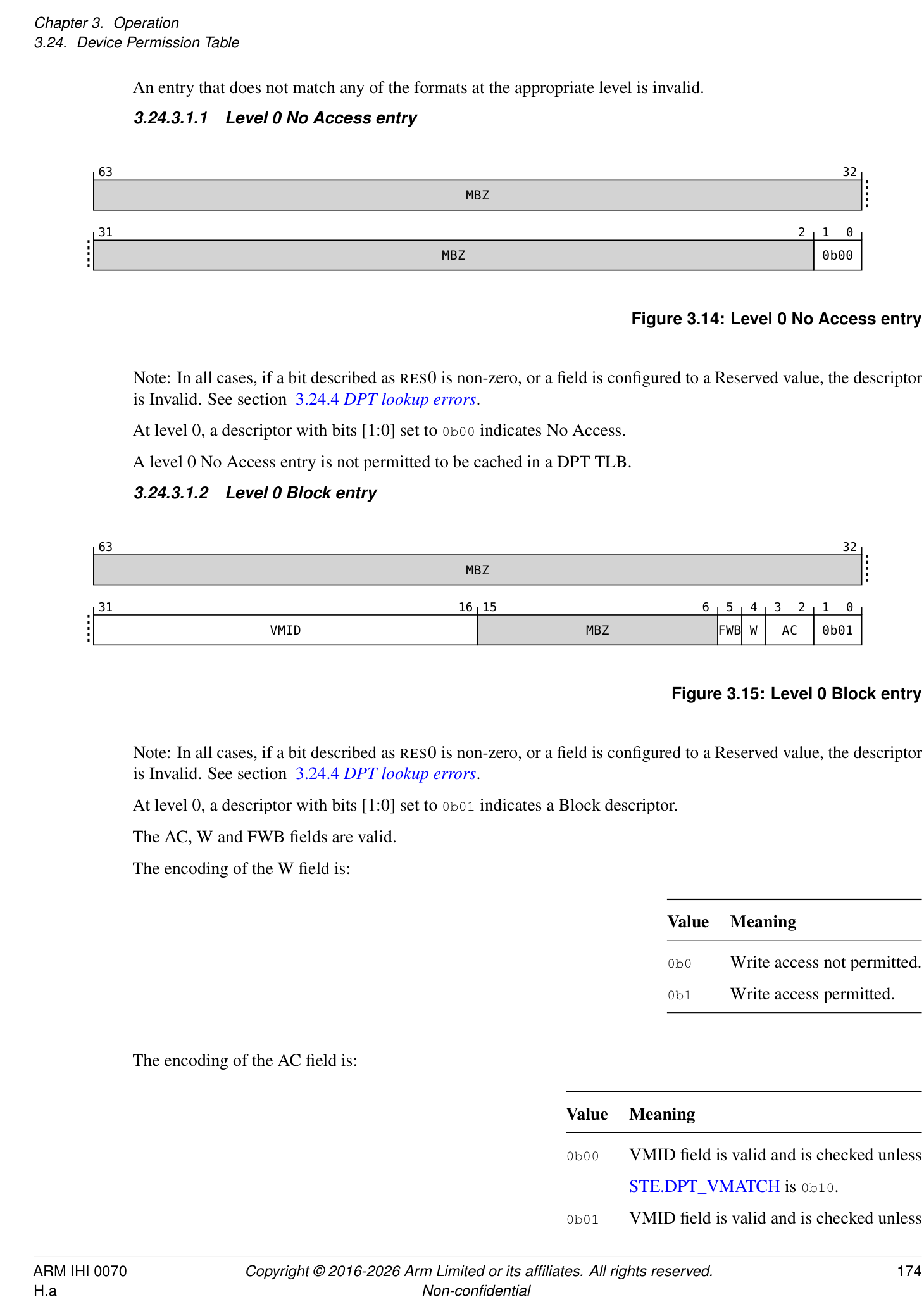
Note: In all cases, if a bit described as RES0 is non-zero, or a field is configured to a Reserved value, the descriptor is Invalid. See section 3.24.4 DPT lookup errors .
At level 0, a descriptor with bits [1:0] set to 0b01 indicates a Block descriptor.
The AC, W and FWB fields are valid.
The encoding of the W field is:
| Value | Meaning |
|---|---|
| 0b0 | Write access not permitted. |
| 0b1 | Write access permitted. |
The encoding of the AC field is:
| Value | Meaning |
|---|---|
| 0b00 | VMID feld is valid and is checked unless |
| STE.DPT_VMATCHis 0b10. | |
| 0b01 | VMID feld is valid and is checked unless |
Value Meaning STE.DPT_VMATCH is 0b01 or 0b10. 0b10 VMID field is RES0. 0b11 Reserved, invalid.
Note: For a Realm STE, DPT_VMATCH is always 0b00 and therefore VMID is always checked when AC is 0b00 or 0b01.
Note: For the Realm DPT, the value of AC determines the output PA space.
If SMMU_IDR0.VMID16 is 0, then VMID[15:8] are RES0 regardless of the value of AC.
If SMMU_IDR3.MTCOMB is 1, the encoding of the FWB field is:
| Value | Meaning |
|---|---|
| 0b0 | Incoming memory type passes through unchanged. |
| 0b1 | Incoming memory type is replaced with Normal-iWB-oWB. |
If FWB is 1, then the transaction is Forced-WB.
This further means that the following classes of Translated transactions are transformed as follows:
| Input transaction class | Transformed to… |
|---|---|
| Destructive read | Non-destructive read (read, or read with clean and invalidate) |
| Invalidate | CleanInvalidate |
| Destructive hint | No-op |
If SMMU_IDR3.MTCOMB is 1 and the final memory type is any Normal cacheable type, then all of the following apply:
-
If the incoming transaction specifies a Normal cacheable memory type, then the final cache allocation hints are the incoming cache allocation hints after applying STE.ALLOCCFG.
-
If the incoming transaction does not specify a Normal cacheable memory type, then the final cache allocation hints are Read No-Allocate, Write No-Allocate.
A level 0 DPT Block entry that does not generate a DPT lookup fault is permitted to be cached in a TLB as though the Block is a contiguous region of granules each of the size configured in SMMU_(R_)DPT_BASE_CFG.DPTGS.
3.24.3.1.3 Level 0 Table entry
| 63 56 | 55 32 | ||
| MBZ | Address[55:12] | ||
| 31 12 11 2 1 0 | |||
| Address[55:12] | MBZ | 0b11 |
Figure 3.16: Level 0 Table entry
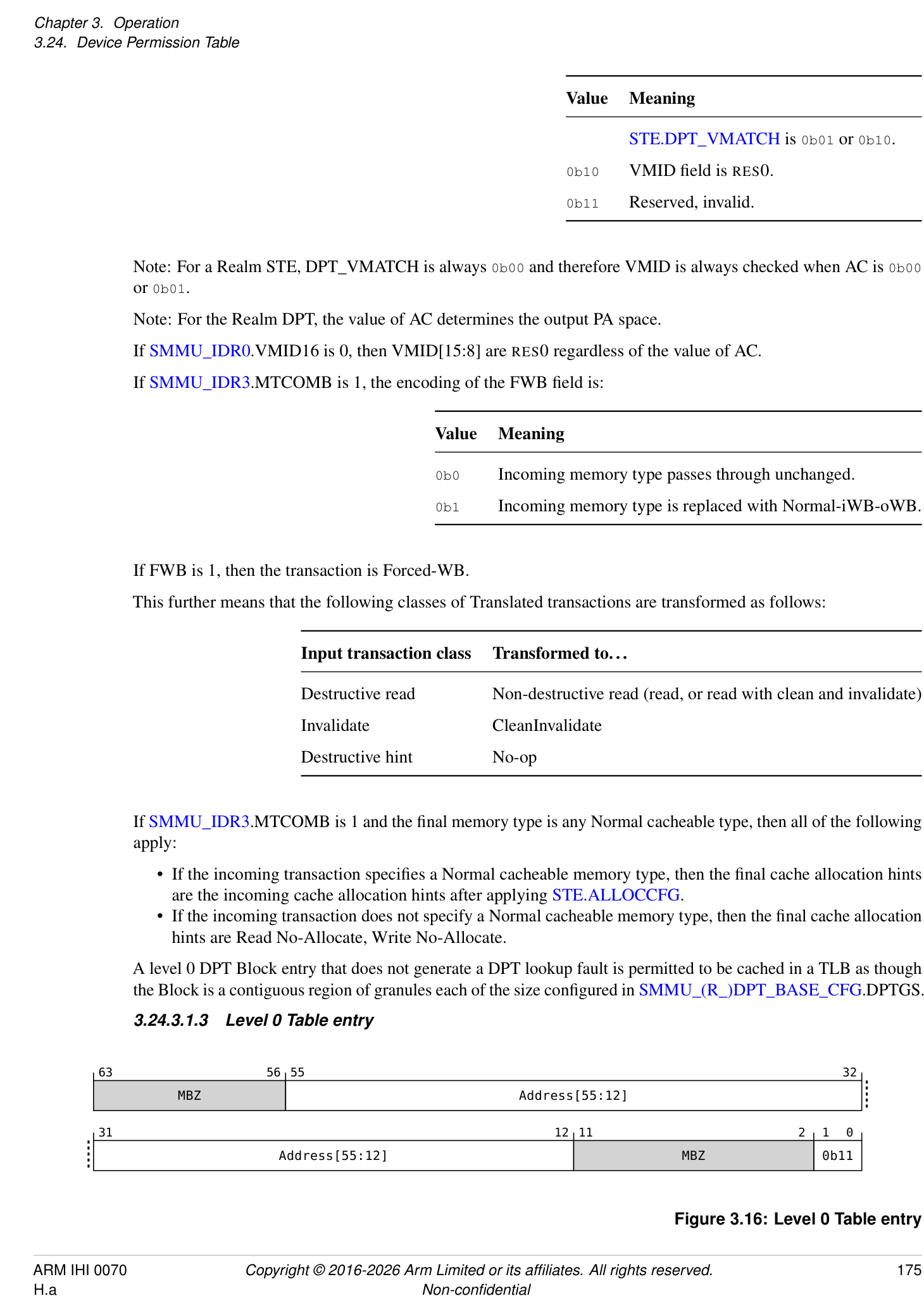
Note: In all cases, if a bit described as RES0 is non-zero, or a field is configured to a Reserved value, the descriptor is Invalid. See section 3.24.4 DPT lookup errors .
At level 0, a descriptor with bits [1:0] set to 0b11 indicates a Table descriptor.
The Address field indicates the next-level base address of a level 1 table.
The address is aligned by the hardware to the size of the level 1 table.
Bits above the implemented physical address size, indicated in SMMU_IDR5.OAS, are RES0.
A level 0 DPT Table entry that does not generate a DPT lookup fault is permitted to be cached in a TLB.
3.24.3.1.4 Level 1 entry
63 48 47 38 37 36 35 34 33 32
VMID1 MBZ W1 AC1 MBZ
FWB1
31 16 15 12 11 8 7 6 5 4 3 2 1 0
VMID0 MBZ Contig MBZ W0 AC0 A[1:0]
FWB0
Figure 3.17: Level 1 entry
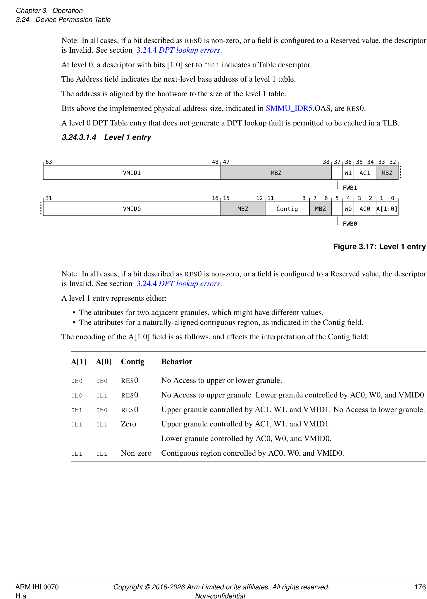
Note: In all cases, if a bit described as RES0 is non-zero, or a field is configured to a Reserved value, the descriptor is Invalid. See section 3.24.4 DPT lookup errors .
A level 1 entry represents either:
-
The attributes for two adjacent granules, which might have different values.
-
The attributes for a naturally-aligned contiguous region, as indicated in the Contig field.
-
The encoding of the A[1:0] field is as follows, and affects the interpretation of the Contig field:
| A[1] | A[0] | Contig | Behavior |
|---|---|---|---|
| 0b0 | 0b0 | RES0 | No Access to upper or lower granule. |
| 0b0 | 0b1 | RES0 | No Access to upper granule. Lower granule controlled by AC0, W0, and VMID0. |
| 0b1 | 0b0 | RES0 | Upper granule controlled by AC1, W1, and VMID1. No Access to lower granule. |
| 0b1 | 0b1 | Zero | Upper granule controlled by AC1, W1, and VMID1. |
| Lower granule controlled by AC0, W0, and VMID0. | |||
| 0b1 | 0b1 | Non-zero | Contiguous region controlled by AC0, W0, and VMID0. |
The encoding of the Contig field is as follows:
| Value | Meaning |
|---|---|
| 0b0000 | No contiguity |
| 0b0001 | 64KB. Reserved if DPTGS is 64KB. |
| 0b0010 | 2MB |
| 0b0011 | 32MB |
| 0b0100 | 512MB |
| 0b0101 | 1GB |
| 0b0110 | 16GB |
| 0b0111 | 64GB |
| Otherwise | Reserved |
If A is 0b00, all other fields in the descriptor are RES0.
If A is 0b01 or 0b10, then Contig is RES0 and the descriptor describes the properties for two granules.
If A is 0b11 and Contig is zero, then the descriptor describes the properties for two granules.
If the descriptor describes the properties for two granules, then:
-
Access to the upper granule is governed by A[1], AC1, W1, FWB1 and VMID1. If A[1] is 0, then the AC1, W1, FWB1 and VMID1 fields are RES0.
-
Access to the lower granule is governed by A[0], AC0, W0, FWB0 and VMID0. If A[0] is 0, then the AC0, W0, FWB0 and VMID0 fields are RES0.
If A is 0b11 and Contig is non-zero, the AC1, W1, FWB1 and VMID1 fields are RES0 and only the AC0, W0, FWB0 and VMID0 fields are considered. The value of Contig indicates the size of the contiguous region.
If Contig is not RES0, then encodings of Contig that select a region size greater than L0DPTSZ are Reserved.
If Contig selects a Reserved encoding, the descriptor is invalid.
If SMMU_IDR0.VMID16 is 0, then VMID0[15:8] and VMID1[15:8] are RES0 regardless of the values of ACx.
The encoding and meaning of the ACx, Wx and FWBx fields is the same as for the AC, W and FWB fields in a Level 0 Block entry.
It is possible that contiguous regions are inconsistently configured in the DPT:
-
In the case where a region is composed of descriptors that provide the same attributes, and differ only by the value of the Contig field, the DPT check is correctly applied.
-
In the case where a region is composed of descriptors that provide different attributes, and the values of the Contig fields produce overlapping regions, the SMMU might use any of the configured attributes in the overlapping regions.
-
If the lookup of a level 1 DPT entry does not generate a DPT lookup fault, then:
-
If Contig is 0, each half of the entry that does not indicate No Access is permitted to be cached in a TLB.
-
If Contig is not RES0 and is non-zero, the entry is permitted to be cached in a TLB as a naturally-aligned contiguous region of granules, each of the size configured in SMMU_(R_)DPT_BASE_CFG.DPTGS.
-
3.24.4 DPT lookup errors
In the DPT check, there are two classes of fault that can occur:
-
The DPT lookup process succeeds, but does not grant access for the transaction being checked. This is referred to as a Device Access fault, and is reported as F_TRANSL_FORBIDDEN. The criteria for generating a Device Access Fault are specified in 3.24.1 DPT check and section 3.24.2.1 DPT TLB caching and Device Access faults .
-
The DPT lookup process fails. This is referred to as a DPT lookup fault, and is reported both in SMMU_(R_)DPT_CFG_FAR and as F_TRANSL_FORBIDDEN. See 7.3.8 F_TRANSL_FORBIDDEN .
The fault reporting priority for DPT lookup faults is as follows:
| Priority | Reason | Reported as | Level |
|---|---|---|---|
| 1 | DPT_WALK_EN = 0 | DPT_DISABLED | 0 |
| 2 | Invalid DPT register confguration | DPT_WALK_FAULT | 0 |
| 3 | GPC fault on level 0 fetch | DPT_GPC_FAULT | 0 |
| 4 | External abort on level 0 fetch | DPT_EABT | 0 |
| 5 | Invalid level 0 descriptor | DPT_WALK_FAULT | 0 |
| 6 | GPC fault on level 1 fetch | DPT_GPC_FAULT | 1 |
| 7 | External abort on level 1 fetch | DPT_EABT | 1 |
| 8 | Invalid level 1 descriptor | DPT_WALK_FAULT | 1 |
If the SMMU encounters any of these faults while performing a DPT lookup, and SMMU_(R_)DPT_CFG_FAR.FAULT = 0, the SMMU reports the information in SMMU_(R_)DPT_CFG_FAR and sets the FAULT bit to 1. If the FAULT bit is already 1, the fault is not reported in SMMU_(R_)DPT_CFG_FAR. When the SMMU makes a fault active in SMMU_(R_)DPT_CFG_FAR, it additionally makes the corresponding SMMU_(R_)GERROR.DPT_ERR active, if the value of SMMU_(R_)GERROR(N).DPT_ERR does not already indicate an active fault. If a fault is observable in SMMU_(R_)GERROR.DPT_ERR, then it has already been made observable in SMMU_(R_)DPT_CFG_FAR.
If a client-originated access generates a DPT lookup fault, and the abort response arising from this is visible to the device, then the corresponding update of SMMU_(R_)GERROR.DPT_ERR is also observable.
If a DPT lookup fault is observable in SMMU_(R_)GERROR.DPT_ERR, or the abort arising from that fault is visible to the client device then completion of a CMD_SYNC on an appropriate Command queue for the Security state guarantees observability of the corresponding F_TRANSL_FORBIDDEN in the Event queue, or that the F_TRANSL_FORBIDDEN has been discarded if the Event queue is unwritable, consistent with the existing rules for Event queue observability.
If the F_TRANSL_FORBIDDEN event arising from a DPT lookup fault is observable, then the corresponding update of SMMU_(R_)GERROR.DPT_ERR is also observable.
The SMMU is not required to report any of these faults if a DPT check can be resolved by a successful DPT TLB lookup.
The following configurations are treated as Invalid DPT register configuration:
-
Reserved value 0b111, or a value exceeding SMMU_IDR5.OAS, for DPTPS.
-
Invalid or Reserved encoding of DPTGS.
-
Invalid or Reserved encoding of L0DPTSZ.
-
Configuration of L0DPTSZ to an address size that exceeds the address sizes in SMMU_IDR5.OAS or DPTPS.
A DPT entry is treated as invalid if any of the following apply:
-
The entry does not match one of the descriptor formats for the given level of lookup.
-
The entry matches one of the formats for the given level of lookup, but has any RES0 bit set to 1 in the descriptor.
-
The entry contains a field that is not RES0 and is configured to a Reserved encoding.
If a DPT_GPC_FAULT is reported then the corresponding GPC fault information is reported in the appropriate SMMU_ROOT_GPT_CFG_FAR or SMMU_ROOT_GPF_FAR register, with REASON = TRANSLATION and FAULTCODE = GPF_WALK_EABT.
If a DPT_EABT is reported as the result of a RAS error, then the corresponding RAS information is reported in RAS syndrome registers, if implemented. See 12.2 Error consumption visible through the SMMU programming interface .
3.24.5 DPT maintenance operations
The DPT maintenance commands remove cached DPT information from DPT TLBs regardless of whether the entry was inserted as the result of a successful ATS translation request or a walk of the DPT.
The CMD_DPTI_ALL and CMD_DPTI_PA commands have the same consumption and completion behavior as for CMD_TLBI_* commands, in that:
-
Consumption of the command does not provide any guarantees.
-
Consumption of a subsequent CMD_SYNC on the same Command queue for which the CMD_DPTI_* command was issued guarantees that the appropriate invalidation has been performed, all Events and faults relating to the invalidated entries have been reported, and all client transactions using the invalidated entries have completed.
Note: Within a given security state, DPT maintenance behaves as follows:
-
CMD_DPTI_ALL is always sufficient to invalidate all cached DPT information.
-
To invalidate cached copies of a Level 0 Table descriptor, a CMD_DPTI_PA with Leaf as 0 and an address anywhere in the region covered by that descriptor is sufficient.
-
To invalidate cached copies of a Level 0 Table descriptor as well as any Level 1 entries in the table pointed to by the Level 0 Table descriptor, a CMD_DPTI_PA with Leaf as 0 and SIZE matching the size of the region pointed to by the Level 0 Table descriptor and address aligned to the size of the region is sufficient.
-
To invalidate cached copies of a Level 0 Block descriptor or Level 1 entries for a contiguous region, a CMD_DPTI_PA with Leaf as 1, SIZE matching the size of the region and an address aligned to the size of the region is sufficient.
-
To invalidate cached copies of the DPT information in one granule of a non-contiguous Level 1 entry, a CMD_DPTI_PA with Leaf=1 and the address of the granule is sufficient.
Note: CMD_TLBI_* Commands and broadcast TLBI operations for stage 1 and stage 2 are not required to invalidate any DPT TLB entries. If an implementation combines GPT and DPT information in DPT TLB entries, TLBI by PA operations remove DPT TLB entries according to the requirements for TLBI by PA operations. Otherwise, TLBI by PA operations are not required to invalidate any DPT TLB entries.
The DPT maintenance operations can be found in 4.6 DPT maintenance .
3.24.6 Software guidance
The DPT is expected, in the general case, to be used to partition physical address space between different EL1 contexts. The statements in this section therefore generally apply to stage 2 translation configuration.
However, it is possible that future use cases might include use of the EL2-E2H StreamWorld, and in that case the statements in this section would apply to stage 1 translation configuration.
3.24.6.1 Access permissions considerations
The DPT configuration for a memory region should be configured to represent the most-permissive access permissions for that memory region, for the final enabled stage of translation. This means that the DPT should grant access for a given granule if any of the following are true for the final enabled stage of translation:
-
The descriptor has AF = 1.
-
The descriptor has AF = 0 and hardware update of the Access Flag is enabled.
This also means that the DPT should grant write access for a given granule if any of the following are true for the final enabled stage of translation:
-
The descriptor grants write access. This includes the case where the descriptor is writable-dirty.
-
The descriptor is writable-clean and HTTU is enabled.
3.24.6.2 Invalid to valid transition
Assuming that initially the translation is Invalid then software must:
-
Configure the DPT to grant access for the granule
-
Perform appropriate cache maintenance and barriers
-
Configure the final enabled stage of translation to grant access for the granule
- Note: TLB maintenance is not required for Invalid to Valid transitions.
3.24.6.3 Valid to invalid transition
When revoking access to a granule, software must:
-
Mark the descriptor in the final enabled stage of translation as Invalid.
-
Perform the appropriate TLBI and sync operation. Note: this means that new ATS translation requests will fail, but Translated transactions may still succeed.
-
Perform the appropriate CMD_ATC_INV and sync operation. Note: This means the device should not issue ATS Translated transactions, other than write-backs in case of a fully-coherent device.
-
If the StreamID is associated with a fully-coherent device, issue the appropriate CMOs for the granule. This might result with device write-backs.
-
Mark the DPT configuration as invalid. Note: This means that rogue ATS Translated transactions might succeed or fail.
-
Perform the appropriate CMD_DPTI_* and sync operation. Note: This means that rogue ATS Translated transactions will fail.
3.24.6.4 Clearing DPT lookup errors
DPT lookup errors for a Security state are reported in both SMMU_(R_)DPT_CFG_FAR and SMMU_(R_)GERROR.DPT_ERR, if they are not already active. This means that the algorithm for clearing a DPT lookup error, once the error is resolved, is as follows:
-
Write 0 to SMMU_(R_)DPT_CFG_FAR.FAULT. Note: This will clear the whole register to zero.
-
Acknowledge SMMU_(R_)GERROR.DPT_ERR by writing SMMU_(R_)GERRORN.DPT_ERR to the same value.
-
Read SMMU_(R_)DPT_CFG_FAR.FAULT again to see if a new fault occurred between steps 1 and 2.
See also:
- 3.24.4 DPT lookup errors .
3.24.7 Considerations for configuring Split-stage ATS versus Full ATS with DPT checking
This section is informative.
If a use case relies on direct device access to physical address space, Full ATS with DPT checks must be configured for functional, not security reasons. If direct device access to physical address space is not required, then Split-stage ATS is preferable to configuration of Full ATS with DPT checks. The two approaches have comparable protection and performance characteristics, but Split-stage ATS is simpler to configure.
Functional considerations:
- If the device interface requires direct access to physical address space, for example if it has a fully coherent cache or if PCIe peer-to-peer routing is required without routing transactions via the host Root Port, Full ATS is required in order for address-based routing to function correctly.
Security considerations:
-
Both configurations still enforce granule protection checks and limit access from a device to the physical address footprint of the guest in question.
-
Split-stage ATS permits the SMMU to enforce stage 2 permissions checks on Translated transactions, at a granularity of read/write/execute. Full ATS with DPT cannot distinguish these levels of permission.
Performance considerations:
-
If Split-stage ATS is used, the EL2 software managing the SMMU does not need to configure the DPT for granules associated with that StreamID, and can therefore avoid the overhead of having to update the table and issue CMD_DPTI_* operations.
-
SMMU lookup performance and cacheability is expected to be comparable between the two different configurations. On a TLB miss, DPT lookup is likely to result in fewer levels of walk.
3.25 Granule Protection Checks
The Realm Management Extension (FEAT_RME) [2] specifies the behavior of granule protection checks. An SMMU with RME performs the same checks for non-PE Requesters.
The SMMU behavior is similar to that defined in FEAT_RME, FEAT_RME_GPC2, FEAT_RME_GPC3, and FEAT_RME_GDI in the following areas:
-
GPT format (the GPT encodings are identical, but their interpretation may differ between a PE and the SMMU. For example, this applies to the GDI encodings).
-
Invalidation and synchronization mechanisms for GPT updates (these are the same in a PE and the SMMU).
The SMMU configuration registers for the GPT base address and format are equivalent to those in FEAT_RME.
See also 17.4 Assignment of PARTID and PMG for SMMU-originated transactions .
Granule protection checks are enabled only when SMMU_ROOT_CR0.GPCEN is 1. All statements in this section that describe how granule protection checks are performed only apply when granule protection checks are enabled.
3.25.1 Client-originated accesses
Accesses to all physical addresses, except for fetches of GPT information, are subject to granule protection checks.
A client-originated access that experiences a GPC fault is signaled to the client device in the same manner as an External abort.
A client-originated access that experiences a GPC fault on the output address of the access is not reported in the Event queue.
3.25.1.1 GPC for client devices without a StreamID
Granule protection checks also apply to accesses from client devices that are not associated with a StreamID. These devices are referred to as NoStreamID devices.
NoStreamID devices only access PA space, and are not associated with any stage 1 or stage 2 translation configuration.
The GPC fault reporting behavior for accesses from NoStreamID devices is the same as for regular client-originated accesses.
NoStreamID devices are not associated with a SEC_SID value.
Transactions issued by a NoStreamID device include both a physical address and a PA space.
An access from a NoStreamID device with a physical address that exceeds the implemented output address size, advertised in SMMU_IDR5.OAS, is terminated with an abort and no Event record or fault is recorded.
The SMMU does not perform any architectural transformations or overrides on NoStreamID accesses, but the SMMU may apply protocol-specific normalization on transaction attributes.
Note: Accesses from System Agent (SA) clients are NoStreamID accesses and are therefore subject to granule protection checks. See 3.25.10.2 System Agent (SA) .
3.25.1.2 Speculative and hint accesses
Note: The SMMU does not report faults encountered during a speculative translation request, translation of transactions marked as speculative, prefetch commands, or for NW-DCP or DH transactions. See also 3.14 Speculative accesses .
For an SMMU with RME, GPC faults encountered during a speculative translation request, translation of transactions marked as speculative, prefetch commands, or for NW-DCP or DH transactions, are reported as follows:
-
No event record is generated.
-
If SMMU_IDR0.RME_IMPL = 0, it is CONSTRAINED UNPREDICTABLE whether the GPC fault is reported or not reported. If it is reported, then it is reported in the appropriate SMMU_ROOT_GPF_FAR or SMMU_ROOT_GPT_CFG_FAR register, if that register does not already contain an active fault.
-
If SMMU_IDR0.RME_IMPL = 1, the granule protection check fault is not reported.
For speculative translation requests, then:
-
If SMMU_IDR0.RME_IMPL = 0, it is CONSTRAINED UNPREDICTABLE whether the GPC on the output address of a translation request is applied at the time of the translation or only when a transaction using the translation is issued.
-
If SMMU_IDR0.RME_IMPL = 1, the GPC on the output address of a translation request is applied at the time of the translation.
3.25.2 Interactions with PCIe ATS
Consistent with the rules for all accesses, all PCIe client transactions are subject to granule protection checks.
The SMMU_CR0.ATSCHK bit has no effect on granule protection checks.
If an SMMU-originated access experiences a GPC fault while servicing an ATS Translation Request, the SMMU responds to the ATS Translation Request as Completer Abort.
If an ATS Translation Request is completed with Success and R == W == 0, the address in the Translation Completion is not valid and it is not subject to granule protection checks.
If SMMU_IDR0.RME_IMPL == 1, RME features are supported and the SMMU performs the GPC on the output address for the result of an ATS Translation Request before sending the completion.
The SMMU returns a translation region size in the ATS Translation Completion such that the GPC passes for accesses to anywhere in the region.
If SMMU_IDR0.RME_IMPL == 0, the SMMU is permitted but not required to perform a GPC on the output address for the result of an ATS Translation Request.
If the output address for an ATS Translation Request fails a GPC, the SMMU responds to the ATS Translation Request as Completer Abort.
ATS Translated transactions are subject to granule protection checks.
An ATS Translated transaction that fails the GPC is terminated with an abort.
Granule protection checks for an ATS Translation Request with PM = 1 are the same as for the equivalent Untranslated transaction. This means that NSP enforcement rules apply to that transaction. See 3.25.10.1.2 Granule Protection Checks for NSP .
For an ATS Translation Request that has PM = 1, all of the following are true:
-
If the GPC forbids the access only because it requires write permission, the result is a successful ATS Translation Completion with W == 0, and with R and Exe resolved by all enabled stages of translation.
-
If the GPC forbids the access for any other reason, the result is an ATS Translation Completion with Completer Abort (CA) status.
Note: A device must distinguish between the permissions granted for a PM = 0 Translation Request and those granted for a PM = 1 Translation Request. For example, this can be achieved by tagging translations in an ATC with the PM attribute and considering it during cache lookups. An ATC must correctly process an ATS Invalidation request regardless of the PM value associated with a translation.
See section 3.25.10.1.1 Protected Mode .
3.25.3 SMMU-originated accesses
An SMMU-originated access that experiences a GPC fault is reported as though it had experienced an External abort.
Consistent with the behavior of F_STE_FETCH, F_CD_FETCH, F_VMS_FETCH and F_WALK_EABT, signaling and reporting of these failures is not affected by the value of the CD.{A, R, S} bits nor the STE.{S2S, S2R} bits.
For an SMMU with SMMU_IDR0.RME_IMPL == 1:
-
For each of the F_STE_FETCH, F_CD_FETCH, F_VMS_FETCH and F_WALK_EABT event records, there is a new field at bit 80 named GPCF.
-
An F_STE_FETCH, F_CD_FETCH, F_VMS_FETCH or F_WALK_EABT arising from a GPC fault is reported with GPCF=1.
-
An F_STE_FETCH, F_CD_FETCH, F_VMS_FETCH or F_WALK_EABT arising for a reason other than a GPC fault is reported with GPCF=0. This is unchanged from an SMMU without SMMU_IDR0.RME_IMPL == 1.
For example, if the SMMU experiences a GPC fault:
-
On an access to an STE, it is reported as F_STE_FETCH, with GPCF=1. This is signaled to the client as an External abort.
-
On an access to a Non-secure Event queue, it is reported through SMMU_GERROR.EVENTQ_ABT_ERR.
3.25.4 Reporting of GPC faults
The reasons for a GPC fault are categorized into three groups:
-
Faults arising from an access to a Location forbidden by the GPT configuration, referred to as a Granule Protection Fault (GPF).
-
Faults arising from misconfiguration of SMMU_ROOT_GPT_BASE, SMMU_ROOT_GPT_BASE_CFG or the GPT, referred to as a GPT lookup error .
-
Faults arising from RAS errors.
The following error conditions represent a GPF, and are reported in SMMU_ROOT_GPF_FAR:
-
If SMMU_ROOT_GPT_BASE_CFG.APPSAA is 0 and an access to a PA space other than Non-secure has a physical address that exceeds the range configured in SMMU_ROOT_GPT_BASE_CFG.PPS. See 3.25.9 Accesses above the protected address space .
-
An access was attempted to a location that is forbidden by the GPT configuration. Note: The accesses that are forbidden by the GPT configuration are extended by Granular Data Isolation (GDI). See 3.25.10 Granular Data Isolation .
The following error conditions represent a GPT lookup error, and are reported in SMMU_ROOT_GPT_CFG_FAR:
-
Fields in SMMU_ROOT_GPT_BASE_CFG are configured to reserved values.
-
Configuration of SMMU_ROOT_GPT_BASE_CFG.PPS to exceed SMMU_IDR5.OAS.
-
Configuration of SMMU_ROOT_GPT_BASE_CFG.{SH, IRGN, ORGN} to an invalid combination.
-
SMMU_ROOT_GPT_BASE.ADDR is configured to exceed the size configured in SMMU_ROOT_GPT_BASE_CFG.PPS.
-
The output address of a GPT Table Entry exceeds the size configured in SMMU_ROOT_GPT_BASE_CFG.PPS.
-
The SMMU depends on using values in an invalid GPT Entry.
-
The SMMU experienced an External abort while fetching a GPT Entry.
-
The SMMU experienced a RAS error while fetching a GPT Entry. This is reported in the same manner as if the SMMU experienced an External abort while fetching a GPT Entry.
3.25.5 SMMU behavior if a GPC fault is active
If a client-originated or SMMU-originated access experiences a GPF reported in SMMU_ROOT_GPF_FAR, then:
-
If there is no prior GPF in SMMU_ROOT_GPF_FAR, the appropriate syndrome information is recorded in SMMU_ROOT_GPF_FAR.
-
Other accesses that do not experience a GPF or GPT lookup error continue as specified.
-
The GPF remains active until software writes 0 to SMMU_ROOT_GPF_FAR.FAULT.
If a client-originated or SMMU-originated access experiences a GPT lookup error reported in SMMU_ROOT_GPT_CFG_FAR, then:
-
If there is no prior GPT lookup error in SMMU_ROOT_GPT_CFG_FAR, the appropriate syndrome information is recorded in SMMU_ROOT_GPT_CFG_FAR.
-
Other accesses that do not experience a GPF or GPT lookup error continue as specified.
-
The GPT lookup error remains active until software writes 0 to SMMU_ROOT_GPT_CFG_FAR.FAULT.
An SMMU with RME has two additional edge-triggered wired interrupts:
| Source | Trigger reason |
|---|---|
| GPF_FAR | An error becomes active inSMMU_ROOT_GPF_FAR. |
| GPT_CFG_FAR | An error becomes active inSMMU_ROOT_GPT_CFG_FAR. |
3.25.6 Observability of GPC faults
If the termination of a client transaction as a result of a GPC fault is observable to the client device, then:
-
If the appropriate SMMU_ROOT_GPF_FAR or SMMU_ROOT_GPT_CFG_FAR register already contained an active fault, then it is not updated in this case.
-
If the appropriate SMMU_ROOT_GPF_FAR or SMMU_ROOT_GPT_CFG_FAR register did not already contain an active fault, then the related syndrome information is observable in the appropriate register.
If an interrupt indicating the presence of a GPC fault is observable, then the syndrome information is observable in the SMMU_ROOT_GPF_FAR or SMMU_ROOT_GPT_CFG_FAR register as appropriate.
If the termination of a client transaction as a result of a GPC fault has been observable to the client device, completion of a subsequent CMD_SYNC guarantees observability of any related events in the Event queue or, if the Event queue is unwritable, that the Event will not become observable.
For an SMMU with SMMU_ROOT_IDR0.BGPTM == 1, then:
-
After completion of a broadcast TLBI PA and DSB instruction on the PE, completion of a subsequent CMD_SYNC guarantees that no Events relating to GPT configuration invalidated by that TLBI and DSB will later be made observable in the Event queue.
-
After a broadcast TLBI PA instruction on the PE, completion of a subsequent DSB instruction guarantees that any errors reported in the SMMU_ROOT_GPF_FAR or SMMU_ROOT_GPT_CFG_FAR registers relating to GPT configuration invalidated by that TLBI are already observable.
For an SMMU with SMMU_ROOT_IDR0.RGPTM == 1, then:
-
After completion of a register-based TLBI by PA, indicated by SMMU_ROOT_TLBI_CTRL.RUN, completion of a subsequent CMD_SYNC guarantees that no Events relating to GPT configuration invalidated by that TLBI by PA will later be made observable in the Event queue.
-
Completion of a register-based TLBI by PA, indicated by SMMU_ROOT_TLBI_CTRL.RUN, guarantees that any errors reported in the SMMU_ROOT_GPF_FAR or SMMU_ROOT_GPT_CFG_FAR registers relating to GPT configuration invalidated by that TLBI by PA are already observable.
If an F_STE_FETCH, F_CD_FETCH, F_VMS_FETCH or F_WALK_EABT with GPCF == 1 is observable in the Event queue then either:
-
If the appropriate SMMU_ROOT_GPF_FAR or SMMU_ROOT_GPT_CFG_FAR register already contained an active fault, then it is not updated in this case.
-
If the appropriate SMMU_ROOT_GPF_FAR or SMMU_ROOT_GPT_CFG_FAR register did not already contain an active fault, then the related syndrome information is observable in the appropriate register.
If an update to SMMU_(*_)GERROR resulting from a GPC fault is observable, then either:
-
If the appropriate SMMU_ROOT_GPF_FAR or SMMU_ROOT_GPT_CFG_FAR register already contained an active fault, then it is not updated in this case.
-
If the appropriate SMMU_ROOT_GPF_FAR or SMMU_ROOT_GPT_CFG_FAR register did not already contain an active fault, then the related syndrome information is observable in the appropriate register.
If a fault to be reported in SMMU_()GERROR is observable in SMMU_ROOT_GPF_FAR or SMMU_ROOT_GPT_CFG_FAR, then the fault will also be reported in SMMU()GERROR in finite time. The existing mechanisms for ensuring the visibility of errors in SMMU(*_)GERROR also apply in this case. For example, completion of an Update of SMMU_CR0.EVENTQEN to 0 guarantees observability of any errors to be reported in SMMU_GERROR.EVENTQ_ABT_ERR.
3.25.7 DCMDQ-related GPC faults
If SMMU_(*_)IDR6.DCMDQ is 0b01, a GPF or GPT lookup error generated by any of the DCMDQ-related operations listed below is reported in both:
-
SMMU_(*_)ECMDQ_CONSn.{HS_ERR, HS_ERR_REASON}.
-
SMMU_ROOT_GPF_FAR.{REASON, FAULTCODE} or SMMU_ROOT_GPT_CFG_FAR.{REASON, FAULTCODE}.
| Access type | Value of REASON | Value of FAULTCODE | Value of HS_ERR_REASON |
|---|---|---|---|
| STE fetch (for DCMDQ | TRANSLATION | GPF_STE_FETCH | HERROR_IPA(1) |
| command | |||
| fetch/CMD_SYNC MSI | |||
| translation) | |||
| Stage 2 walk (for | TRANSLATION | GPF_WALK_EABT | HERROR_IPA(1) |
| DCMDQ command | |||
| fetch/CMD_SYNC MSI | |||
| translation) | |||
| DCMDQ fetch | GERROR | DCMDQ_GPF | HERROR_IPA(1) |
| CIT/VSTT fetch | TRANSLATION | GPF_CIT_FETCH or | HERROR_SID_EABT |
| GPF_VSTT_FETCH | |||
| MSI following | GERROR | MSI_CMDQ_GPF | HERROR_MSI_ABT(2) |
| CMD_SYNC |
(1) GPC faults on these accesses are not reported as though they have experienced an External abort. This behavior differs from other SMMU-originated accesses experiencing a GPC fault.
(2) In line with the reporting of HERROR_MSI_ABT as described in 3.5.7.7 DCMDQ Errors and Faults , the External abort is observable on the subsequent CMD_SYNC.
3.25.8 Non-secure Only (NSO)
This section applies only when SMMU_ROOT_IDR0.NSO is 1.
If SMMU_ROOT_GPT_BASE_CFG.NSO is 1, Granule Protection Checks are extended to support the Non-secure Only (NSO) GPI field encoding introduced in the Armv9.5 architecture[2]. The NSO encoding specifies that accesses to the Non-secure PA space are permitted only by the Non-secure or Root Security states.
If SMMU_ROOT_GPT_BASE_CFG.NSO is 1, then an access to a location that is marked as NSO by a GPT descriptor is forbidden when any of the following are true:
• The access originates from a Realm StreamID. This includes accesses to the Non-secure PA space.
• The access originates from a Secure StreamID. This includes accesses to the Non-secure PA space.
- The access is a NoStreamID access to any PA space other than the Non-secure PA space.
Note: A forbidden access, as described above, causes a GPF to be reported. For more information, see 3.25.4 Reporting of GPC faults .
3.25.9 Accesses above the protected address space
This section applies only when SMMU_ROOT_IDR0.APPSAA is 1.
The SMMU_ROOT_GPT_BASE_CFG.APPSAA register field controls the behavior of accesses that have physical addresses above the protected address space, as configured in SMMU_ROOT_GPT_BASE_CFG.PPS.
If SMMU_ROOT_GPT_BASE_CFG.APPSAA is 0, for an access with a physical address above the protected address space, all of the following apply:
-
The access must be to the Non-secure PA space.
-
If the access is to any PA space other than the Non-secure PA space, it causes a level 0 Granule Protection Fault (GPF).
Note: For more information, see 3.25.4 Reporting of GPC faults .
Note: If SMMU_ROOT_GPT_BASE_CFG.APPSAA is 0, locations that are above the protected address space are effectively marked by the GPT as NS.
If SMMU_ROOT_GPT_BASE_CFG.APPSAA is 1, an access with a physical address that is above the protected address space is permitted to be to any PA space.
Note: If SMMU_ROOT_GPT_BASE_CFG.APPSAA is 1, locations that are above the protected address space are effectively marked by the GPT as All Accesses Permitted.
3.25.10 Granular Data Isolation
Granular Data Isolation (GDI) provides support for two additional PA spaces:
-
Non-secure Protected (NSP) . See 3.25.10.1 Non-secure Protected (NSP) .
-
System Agent (SA) . See 3.25.10.2 System Agent (SA) .
The GPT is extended to support new GPI encodings, as described in the following table:
| Value | Meaning |
|---|---|
| 0b0100 | Accesses permitted to System Agent (SA) PA space only. |
| 0b0101 | Accesses permitted to Non-secure Protected (NSP) PA space in compliance with NSP enforcement |
| rules. See section: 3.25.10.1.2_Granule Protection Checks for NSP_. | |
| 0b0110 | Reserved. |
| 0b0111 | Reserved. |
Note: The interpretation of these GPI encodings differs between the PE and the SMMU.
These GPI encodings are enabled using the following controls:
-
SMMU_ROOT_GPT_BASE_CFG.SA for SA.
-
SMMU_ROOT_GPT_BASE_CFG.NSP for NSP.
Otherwise these encodings are considered to be reserved for the purpose of GPT descriptor validity checks.
If SMMU_ROOT_IDR0.GDI is 1, L1 GPT descriptor validity checks must be performed on a pair of L1 GPT descriptors within a naturally aligned 16-byte region of memory. An individual L1 GPT descriptor is valid only when both descriptors within the pair are valid.
For information on the effect of GDI on PMCG, MPAM and MEC, see:
-
10.4 StreamIDs and filtering .
-
17.7 Determination of PARTID space values .
-
Chapter 18 Support for Memory Encryption Contexts .
3.25.10.1 Non-secure Protected (NSP)
The following sections apply only when SMMU_ROOT_IDR0.GDI is 1.
3.25.10.1.1 Protected Mode
The NSP PA space is accessible only by Non-secure SMMU client devices when they are in Protected Mode (PM) .
If SMMU_ROOT_IDR0.GDI is 1, the SMMU architecture is extended to support the PM attribute, which is associated with Non-secure streams.
The presence of the PM attribute in accesses is determined as follows:
-
Accesses associated with the Non-secure state (for example, accesses from Non-secure StreamIDs) always specify a PM attribute.
-
The following accesses do not specify a PM attribute:
-
Accesses associated with the Realm state.
-
Accesses associated with the Secure state.
-
Accesses from NoStreamID clients.
-
The PM attribute propagates with a request and is presented to the Granule Protection Check along with the resolved PA and PA space.
The SMMU does not support overrides for the PM attribute. If a client device does not provide a PM attribute, it takes a default value of 0.
If SMMU_ROOT_CR0.GPCEN is 0 or SMMU_ROOT_GPT_BASE_CFG.NSP is 0, the PM attribute is treated as 0 for the purpose of resolving the output PA space.
For SMMU-originated accesses, the PM attribute is always 0.
Note: An SMMU client sets the PM attribute on a transaction if it contains, or is derived from, data associated with the Protected Mode. The rules for client entry and exit from Protected Mode are outside of the scope of this specification.
Note: If SMMU_ROOT_IDR0.GDI is 0, PM inputs are ignored by the SMMU.
If any of the following event records are generated as a result of a transaction with PM = 1, they are converted to an F_PROTECTED event record before being written to the event queue:
-
7.3.2 F_UUT .
-
7.3.6 F_BAD_ATS_TREQ .
-
7.3.8 F_TRANSL_FORBIDDEN .
-
7.3.12 F_WALK_EABT .
-
7.3.13 F_TRANSLATION .
-
7.3.14 F_ADDR_SIZE .
-
7.3.15 F_ACCESS .
-
7.3.16 F_PERMISSION .
-
7.3.17 F_TLB_CONFLICT .
-
7.3.19 E_PAGE_REQUEST .
Note: See also 7.3.21 F_PROTECTED .
For all other event records, the SMMU guarantees that IMPLEMENTATION DEFINED fields do not include information that is derived from the client transaction attributes, other than the StreamID or the SubstreamID.
Note: This guarantee prevents malicious disclosure of protected information through input addresses. An MMU fault generated by an access with PM = 1 might be fatal to the stream, because the event record does not provide
software with sufficient information to handle it. Software should take this restriction into account when configuring translation tables for devices with PM = 1. For example, NSP pages must be statically mapped to avoid Translation faults.
For an ordinary transaction that generates an event that is converted to an F_PROTECTED event, a corresponding ATS Translation Request with the same properties is handled as specified in section 3.9.1.2 Responses to ATS Translation Requests for the original event.
Additional restrictions apply for Protected Mode transactions. For more information, see:
-
7.5 Global error recording .
-
3.13.1 Software update of flags .
-
3.13.2 Access flag hardware update .
-
3.12.2 Stall model .
For information on the effect of the PM attribute on PCIe and ATS, see:
-
13.7 PCIe permission attribute interpretation .
-
3.25.2 Interactions with PCIe ATS .
For information on the effect of the PM attribute on DPT checks and DPT caching, see:
-
3.24.1 DPT check .
-
3.24.2 DPT caching behavior .
3.25.10.1.2 Granule Protection Checks for NSP
If SMMU_ROOT_GPT_BASE_CFG.NSP is 1, NSP enforcement rules apply. This means that accesses forbidden by the GPT configuration are extended to include the following cases:
-
An access to a location marked by the GPT as NSP, where any of the following apply:
-
The access is associated with the Non-secure state and has PM = 0.
-
The access is associated with the Realm state.
-
The access is associated with the Secure state.
-
The access is a NoStreamID access in a PA space other than NSP.
-
-
An access that is to a location marked by the GPT as either NS, NSO or All Accesses Permitted, where all of the following apply:
-
The access is associated with the Non-secure state.
-
The access requires write permission.
-
The access has PM = 1.
-
The SMMU overrides the output PA space of an access to NSP if both of the following apply:
-
The access originates from a Non-secure StreamID with PM = 1.
-
The access is to a location that is marked as NSP by the GPT.
Certain transactions requiring write permission are downgraded by the SMMU if write permission is not granted. For such transactions, if the GPC forbids them only because of the missing write permission, the GPC behavior is as described in the following sections:
-
3.22 Destructive reads and directed cache prefetch transactions .
-
16.7.2 Non-data transfer transactions .
This means that a GPF is not reported, and that the GPC behavior is as follows:
| Operation type | GPC behavior if no write permission |
|---|---|
| Destructive read | Transformed into a read or read with clean and invalidate. |
| Invalidate | Transformed into a CleanInvalidate operation. |
| Destructive hint | Invalidate does not occur. |
Note: The SMMU might observe accesses from NoStreamID devices that specify NSP as an input PA space. For example, an access issued by a debug port with privileges to access the NSP PA space. The NSP enforcement rules allow such accesses if the location is marked by the GPT as NSP, or as All Accesses Permitted (since these accesses do not specify a PM attribute). This means that there are two scenarios in which the output PA space of the access is NSP:
-
A Non-secure StreamID access has PM = 1 and the location is marked as NSP in the GPT.
-
A NoStreamID access has PAS = NSP and the location is marked as NSP or All Accesses Permitted in the GPT.
Note: Locations that are above the PPS are effectively marked by the GPT as either NS or All Accesses Permitted, depending on the configuration of SMMU_ROOT_GPT_BASE_CFG.APPSAA == 1. Locations within a GPC bypass window are effectively marked by the GPT as All Accesses Permitted. For more information, see 3.25.9 Accesses above the protected address space .
3.25.10.2 System Agent (SA)
This section applies only when SMMU_ROOT_IDR0.GDI is 1.
All System Agent (SA) clients are NoStreamID devices.
Note: Only NoStreamID devices are capable of generating accesses in the SA PA space.
Note: The SMMU does not limit the set of PA spaces that a specific NoStreamID device can express. System integration must guarantee that each NoStreamID device can access only the set of PA spaces permitted by its Security state and by the system’s External Debug State. Accordingly, system integration must guarantee that a SA client can issue accesses only to the SA PA space and Non-secure PA space.
If SMMU_ROOT_GPT_BASE_CFG.SA is 1, accesses forbidden by the GPT configuration are extended to include any access where both of the following apply:
-
The access is in a PA space that is not SA.
-
The access is to a location marked by the GPT as SA.
Note: An access in the SA PA space is permitted only if the location is marked by the GPT as either of the following:
-
SA.
-
All Accesses Permitted.
Note: If SMMU_ROOT_GPT_BASE_CFG.SA is 1, the SMMU Root programming interface is exclusively controlled by an agent trusted by all System Agent clients.
3.26 Permission Indirections
The Armv8.9 architecture[2] introduces a permissions indirection scheme, for stage 1 and stage 2 independently. This section describes the corresponding SMMU architecture changes for this feature.
3.26.1 Stage 1 permission indirections
Note: PIIndex is a translation table descriptor field, introduced by FEAT_S1PIE in the A-profile architecture[2].
Stage 1 permissions are determined according to feature support and control bits as follows:
| SMMU_IDR3.S1PI | STE.S1PIE | CD.PIE | Result |
|---|---|---|---|
| 0 | RES0 | RES0 | Stage 1 permission indirections are not supported and stage 1 |
| permissions are determined directly from stage 1 translation | |||
| tables. | |||
| 1 | 0 | RES0 | Stage 1 permissions are determined directly from stage 1 |
| translation tables. | |||
| 1 | 1 | 0 | Stage 1 permissions are determined directly from stage 1 |
| translation tables. | |||
| 1 | 1 | 1 | Stage 1 permissions are determined fromCD.PIIP, and |
| CD.PIIUif appropriate, using PIIndex from the stage 1 | |||
| descriptors. |
Note: The STE.S1PIE control allows a hypervisor to prevent stage 1 configuration of permission indirections, for StreamIDs where Context Descriptors are controlled directly by a guest. In this case, the hypervisor is expected to present an emulated SMMU without support for permission indirections to the guest.
Note: The SMMU does not support the stage 1 permission overlay feature present in the PE architecture.
If the stage 1 Indirect Permission Scheme is enabled, then CD.WXN is RES0 and has no effect.
If the stage 1 Indirect Permission Scheme is enabled, the stage 1 permissions are computed as follows:
-
The permissions are decoded from CD.PIIU[PIIndex] and CD.PIIP[PIIndex].
-
For the NS-EL1, Secure, Realm-EL1 and any-EL2-E2H StreamWorlds, CD.PAN is applied as follows:
-
If CD.PAN is 1 and any Unprivileged access is granted then Privileged read and write permissions are removed. This applies regardless of the value of CD.EPAN.
-
It is IMPLEMENTATION DEFINED whether this step is performed here or after step 4.
-
-
For a translation for Secure state, then if SMMU_S_CR0.SIF is 1 and the stage 1 output address is Non-secure, then both Privileged execute and Unprivileged execute permission are removed.
-
For a translation for Realm state, then if the stage 1 output address is Non-secure, then both Privileged execute and Unprivileged execute permission are removed. This permissions computation is not affected by CD.{EPD0, EPD1, E0PD0, E0PD1}.
3.26.2 Stage 2 permission indirections
Note: POIndex is a translation table descriptor field, introduced by FEAT_S2POE in the A-profile architecture[2].
Stage 2 permissions are determined according to feature support and control bits as follows:
| SMMU_IDR3.S2PI | STE.S2PIE | STE.S2POE | Result |
|---|---|---|---|
| 0 | RES0 | RES0 | Stage 2 permission indirections are not supported and stage |
| 2 permissions are determined directly from stage 2 | |||
| translation tables. | |||
| 1 | 0 | 0 | Stage 2 permissions are determined directly from stage 2 |
| translation tables. | |||
| 1 | 0 | 1 | ILLEGAL, generates C_BAD_STE. |
| 1 | 1 | 0 | Stage 2 permissions are determined fromSMMU_S2PII |
| using PIIndex from the stage 2 descriptors. | |||
| 1 | 1 | 1 | Stage 2 permissions are determined fromSTE.S2POIusing |
| POIndex from the stage 2 descriptors, combined with | |||
| SMMU_S2PIIusing PIIndex from the stage 2 descriptors. |
Stage 2 permissions are computed in the following order, and F_PERMISSION events are reported with this priority from highest to lowest:
-
For the stage 2 translation of a stage 1 output address, including next-level table addresses of a stage 1 translation table walk, the AssuredOnly permission check is applied.
-
The Base and Overlay permissions are applied as follows:
-
If permission overlays are enabled, the Overlay permissions are looked up from STE.S2POI indexed by POIndex.
-
If permission indirection is enabled then the Base permissions are looked up from SMMU_S2PII indexed by PIIndex. Otherwise, the Base permissions are taken directly from the translation table descriptor.
-
The base and overlay permissions are combined as described in the A-profile architecture[2] and the resulting permissions are applied.
-
-
For the translation of a stage 1 translation table walk or CD fetch, the effect of STE.S2PTW is applied.
-
For any access that requires write permission, if permission indirection is enabled, the Dirty state permission check is applied.
-
For directed prefetch operations and cache maintenance operations, the effects of STE.DRE and STE.DCP are applied.
3.27 Translation Hardening
3.27.1 Protected attribute
If SMMU_IDR3.THE == 1, SMMU behavior for the stage 1 Protected attribute is the same as for the PE behavior for the Protected attribute, including:
-
The Protected attribute is always present in VMSAv9-128 descriptors.
-
The Protected attribute is only present in VMSAv8-64 descriptors if CD.PnCH is 1.
-
The Contiguous bit is not present in VMSAv8-64 descriptors if CD.PnCH is 1.
Note: The SMMU does not support Read-Check-Write (RCW) operations, and therefore none of the RCW checks are applied by the SMMU.
Note: Unless the STE.AssuredOnly check is enabled, there is no benefit to enabling CD.PnCH in the SMMU, except when VMSAv8-64 stage 1 translation tables for a PE context using the Protected attribute are shared with SMMU contexts, and the SMMU must therefore not interpret bit 52 of Block and Page descriptors as the Contiguous bit.
3.27.2 AssuredOnly permission checks
If SMMU_IDR3.THE == 1, SMMU behavior for the stage 2 AssuredOnly attribute is the same as for the PE behavior for the AssuredOnly attribute, except that:
-
Use of the AssuredOnly attribute is configured via STE.AssuredOnly instead of VTCR_EL2.AssuredOnly.
-
A stage 2 Permission fault that would be reported with ESR_EL2.AssuredOnly set to 1 is instead reported as a stage 2 F_PERMISSION with AssuredOnly set to 1.
-
If a CD, or the L1CD that points to it, is fetched from memory that is not marked AssuredOnly at stage 2, then any access translated from the TTB0 or TTB1 field in that CD does not have the Assured Translation property, and this overrides the Assured Translation property as-defined in the A-profile architecture[2].
-
If a CD, and the L1CD that points to it, is fetched from memory that is marked AssuredOnly at stage 2, then any access translated from the TTB0 or TTB1 field in that CD gets the Assured Translation property according to the definition in the A-profile architecture[2].
Note: The AssuredOnly check does not apply to Context Descriptors. For example, if an L1CD is fetched from memory that is not marked AssuredOnly at stage 2, and the subsequent CD is fetched from memory that is marked as AssuredOnly at stage 2, then this does not result with an AssuredOnly permission fault.
Note: In the PE architecture, if stage 1 translation is disabled, then any access to a region marked AssuredOnly at stage 2 generates a Permission fault. This also applies in the SMMU architecture for any case where stage 1 translation is bypassed, whether because of STE.Config or STE.S1DSS configuration.
For an ATS Translation Request, the AssuredOnly check is performed in the same manner as for a regular transaction, and if the AssuredOnly check fails then the ATS Translation Completion is sent with Success and R == W == 0.
For an ATS Translated Transaction when STE.EATS is 0b10 (Split-stage ATS), then AssuredOnly is ignored for the purposes of determining whether the transaction is permitted.
Commands
Chapter 4 Commands
This section describes the behavior of commands given to the SMMU through the Command queue.
4.1 Commands overview
4.1.1 Command opcodes
All entries in the Command queue are 16 bytes long. All Command queue entries are little-endian. Each command begins with an 8-bit command opcode, defined as follows:
| Command opcode | Command name |
|---|---|
| 0x00 | Reserved |
| 0x01 | CMD_PREFETCH_CONFIG |
| 0x02 | CMD_PREFETCH_ADDR |
| 0x03 | CMD_CFGI_STE |
| 0x04 | CMD_CFGI_STE_RANGE |
| Note: CMD_CFGI_ALLhas the same opcode as this command. | |
| 0x05 | CMD_CFGI_CD |
| 0x06 | CMD_CFGI_CD_ALL |
| 0x07 | CMD_CFGI_VMS_PIDM |
| 0x08 | CMD_CFGI_CIT |
| 0x09 | CMD_CFGI_VSTT_VSID |
| 0x0A | CMD_CFGI_VSTT |
| 0x10 | CMD_TLBI_NH_ALL |
| 0x11 | CMD_TLBI_NH_ASID |
| 0x12 | CMD_TLBI_NH_VA |
| 0x13 | CMD_TLBI_NH_VAA |
| 0x14-0x17 | Reserved |
| 0x18 | CMD_TLBI_EL3_ALL |
| 0x19 | Reserved |
| 0x1A | CMD_TLBI_EL3_VA |
| 0x1B-0x1F | Reserved |
| 0x20 | CMD_TLBI_EL2_ALL |
| 0x21 | CMD_TLBI_EL2_ASID |
| 0x22 | CMD_TLBI_EL2_VA |
| Command opcode | Command name |
|---|---|
| 0x23 | CMD_TLBI_EL2_VAA |
| 0x24-0x27 | Reserved |
| 0x28 | CMD_TLBI_S12_VMALL |
| 0x29 | Reserved |
| 0x2A | CMD_TLBI_S2_IPA |
| 0x2B-0x2F | Reserved |
| 0x30 | CMD_TLBI_NSNH_ALL |
| 0x31-0x3F | Reserved |
| 0x40 | CMD_ATC_INV |
| 0x41 | CMD_PRI_RESP |
| 0x42-0x43 | Reserved |
| 0x44 | CMD_RESUME |
| 0x45 | CMD_STALL_TERM |
| 0x46 | CMD_SYNC |
| 0x47-0x4F | Reserved |
| 0x50 | CMD_TLBI_S_EL2_ALL |
| 0x51 | CMD_TLBI_S_EL2_ASID |
| 0x52 | CMD_TLBI_S_EL2_VA |
| 0x53 | CMD_TLBI_S_EL2_VAA |
| 0x54-0x57 | Reserved |
| 0x58 | CMD_TLBI_S_S12_VMALL |
| 0x59 | Reserved |
| 0x5A | CMD_TLBI_S_S2_IPA |
| 0x5B-0X5F | Reserved |
| 0x60 | CMD_TLBI_SNH_ALL |
| 0x61-0x6F | Reserved |
| 0x70 | CMD_DPTI_ALL |
| Command opcode | Command name |
|---|---|
| 0x71-0x72 | Reserved |
| 0x73 | CMD_DPTI_PA |
| 0x74-0x7F | Reserved |
| 0x80-0x8F | IMPLEMENTATION DEFINED |
| 0x90-0xFF | Reserved |
4.1.2 Submitting commands to the Command queue
Commands are submitted to the SMMU by writing them to the Command queue then, after ensuring their visibility to the SMMU, updating the SMMU_()CMDQ_PROD.WR index which notifies the SMMU that there are commands to process. The SMMU does not execute commands beyond the CMDQ_PROD.WR index and, when commands are able to be processed as described in this chapter, a write to SMMU(_)CMDQ_PROD.WR is all that is required from software to cause the SMMU to consider newly-produced commands. See section 3.21.2 Queues .
Commands are able to be processed from the Command queue when all of the following conditions are met:
-
The Command queue CONS and PROD indexes indicate that the queue is not empty.
-
The Command queue is enabled through SMMU_(*_)CR0.CMDQEN.
-
No Command queue error is active for the given Command queue.
The SMMU processes commands in a timely manner until all commands are consumed, or a command queue error occurs, or the queue is disabled.
When SMMU_IDR0.SEV == 1, the SMMU triggers a WFE wake-up event when a Command queue becomes non-full and an agent external to the SMMU could have observed that the queue was previously full. This applies to the Non-secure Command queue and, if implemented, the Secure Command queue.
Note: Arm expects that an attempt to insert a command into the queue will first observe from SMMU_()CMDQ_CONS whether the queue has space, and if it is full might then poll the SMMU(_)CMDQ_CONS index in a loop until the queue becomes non-full. Such a loop can be throttled using the WFE instruction when the SMMU and system supports sending of WFE wake-up events.
The behaviors of some commands are dependent on SMMU register state. Register state must not be altered between such a command having been submitted to the Command queue and the command completion. If a register field is changed while a dependent command could be being processed, it is UNPREDICTABLE whether the command is interpreted under the new or old register field value.
4.1.3 Command errors
A Command queue CERROR_ILL error occurs when:
-
A Reserved command opcode is encountered.
-
A valid command opcode is used with invalid parameters, see the individual command descriptions.
-
A valid command opcode is used and a Reserved or undefined field is optionally detected as non-zero, which results in the command being treated as malformed.
Some commands, where specified, are IGNORED in certain circumstances. If a command causes a CERROR_ILL this takes precedence over whether the command is IGNORED or not.
A command queue CERROR_ABT error occurs when:
- An external abort is encountered upon accessing memory.
The SMMU stops command consumption immediately upon the first occurrence of an error, so that the SMMU_(*_)CMDQ_CONS.RD index indicates the command that could not be correctly consumed, and the error code is reported. See section 7.1 Command queue errors for details on Command queue error reporting and recovery.
4.1.4 Consumption of commands from the Command queue
A command is Consumed when the value observed in the SMMU_(*_)CMDQ_CONS.RD index register passes beyond the location of the command in the queue. This means that:
-
As defined by the normal circular queue semantics, the location has been read by the SMMU and the producer might later re-use the location for a different command.
-
Where explicitly noted in a command description, certain side effects or guarantees have occurred.
- Where not noted, no conclusions can be drawn from the Consumption of a command.
The SMMU_(*_)CMDQ_CONS index can be polled to determine whether a specific command has been Consumed. See section 4.8 Command Consumption summary for a summary of Consumption behavior.
A CMD_SYNC command is provided as a mechanism to ensure completion of commands submitted to the same queue at a location before the CMD_SYNC, including side effects. A CMD_SYNC is not required to be issued in order to start the processing of earlier commands.
Note: A CMD_SYNC is used where it is necessary to determine completion of prior commands, such as a TLB invalidation, but commands are able to complete without depending on a CMD_SYNC.
4.1.5 Reserved fields
All non-specified fields in the commands are RES0. An implementation is permitted to check whether these fields are zero. An implementation does one of the following:
-
Detects non-zero use of a Reserved field as a malformed command, resulting in CERROR_ILL.
-
Ignores the entirety of any Reserved fields.
Some combinations or ranges of parameter values are defined in this section to be ILLEGAL and use of these values results in a CERROR_ILL command error.
4.1.6 Common command fields
These fields are common to more than one command and have the following behavior:
-
SubstreamID and Substream Valid (SSV)
-
SSV indicates whether a SubstreamID is provided.
-
0: SubstreamID not supplied.
-
1: SubstreamID supplied.
-
-
-
When SMMU_S_IDR1.SECURE_IMPL == 1, SSec is used by commands on the Secure Command queue to indicate whether the given StreamID parameter is Secure or Non-secure, in a similar way to SEC_SID for an input transaction (see section 3.10.1 StreamID Security state (SEC_SID) ):
| SSec | Meaning |
|---|---|
| 0 | StreamID is Non-secure |
| 1 | StreamID is Secure |
-
Commands on the Non-secure Command queue must set SSec == 0, where present, and cannot affect Secure streams. A command on the Non-secure Command queue with SSec == 1 is ILLEGAL, regardless of whether Secure state is supported, and raises CERROR_ILL.
-
For the Realm Command queue, SSec must be set to 0, otherwise CERROR_ILL is raised. See 10.7 Support for Realm state .
-
Virtual address fields are Address[63:12], with [11:0] taken as zero.
-
Physical, or IPA address fields are Address[55:12], or [55:2] for the case of MSIAddr, with other bits taken as zero.
-
Bits[55:52] of these fields are RES0 in SMMUv3.1 to SMMUv3.3.
-
Bits[55:48] of these fields are RES0 in SMMUv3.0.
-
4.1.7 Out-of-range parameters
Providing an out-of-range parameter to a command has one of the following CONSTRAINED UNPREDICTABLE behaviors:
-
The command has no effect
-
The command has an effect, taking an UNPREDICTABLE value for the parameter that is out-of-range.
- Note: For example, an implementation might truncate an out-of-range StreamID parameter to another in-range StreamID which might then be affected by the command.
See section 3.16.1.2 Command Queue . Some implementations might not provide the ability to express out-of-range values in certain fields.
A StreamID parameter for a command on the Non-secure Command queue is out of range if the value exceeds the implemented Non-secure StreamID size, as reported by SMMU_IDR1.SIDSIZE. For a command on the Secure Command queue, a Non-secure StreamID is out of range if the value exceeds the Non-secure SMMU_IDR1.SIDSIZE and a Secure StreamID is out of range if the value exceeds the Secure SMMU_S_IDR1.S_SIDSIZE.
In an SMMU with RME DA, the size of a StreamID parameter for Realm state is the same as for the Non-secure state. This means that when submitting a command to the Realm command queue, the StreamID parameter is out of range if the value exceeds SMMU_IDR1.SIDSIZE.
A SubstreamID parameter is out of range if the value exceeds the implemented SubstreamID size, as reported by SMMU_IDR1.SSIDSIZE.
Address parameter ranges are described for each command type that takes an address parameter.
The allowed range of ASID and VMID parameters is covered in section 4.4 TLB invalidation .
For information about out-of-range parameters during SID translation, see 3.5.9.4 vSID Errors and external aborts .
4.2 Prefetch
Two forms of prefetch command are available which can prefetch the configuration or translation data associated with a stream.
Valid prefetch commands with out of range parameters do not generate command errors. A request to prefetch an address that is out of range with respect to the translation table configuration for the StreamID or SubstreamID is IGNORED and does not record any kind of fault or error.
An implementation is not required to check the range of an Address parameter, but if it does then the parameter is considered out of range if:
-
When the stream configuration enables stage 1 translation, the parameter has bits at Address[VAS-1] and upwards that are not all equal in value. TBI is permitted but not required to apply to the parameter.
-
When the stream configuration enables stage 2 translation, the parameter has bits at Address[IAS] and upwards that are not zero.
If either SMMU_IDR1.SSIDSIZE == 0 or STE.S1CDMax == 0, then:
-
Prefetch commands must be submitted with SSV == 0 and the SubstreamID parameter is IGNORED.
-
Setting SSV == 1 is CONSTRAINED UNPREDICTABLE and has one of the following behaviors: – The command behaves as though SSV == 0.
- The command has no effect.
Prefetch commands directed to invalid configuration, for example, an STE or CD with V == 0 or out of range of the Stream table (or level-2 sub-table), fail silently and do not record error events. Similarly, prefetch commands directed to addresses that cause translation-related faults for any reason do not record error events.
When SMMU_(*_)CR0.SMMUEN == 0, valid prefetch commands are consumed but do not trigger a prefetch.
4.2.1 CMD_PREFETCH_CONFIG(StreamID, SSec, SubstreamID, SSV)
| 127 96 | 127 96 | 127 96 | 127 96 | 127 96 | 127 96 |
|---|---|---|---|---|---|
| RES0 | |||||
| 95 64 | |||||
| RES0 | |||||
| 63 32 | |||||
| StreamID | |||||
| 31 12 11 10 9 8 7 0 | |||||
| SubstreamID | SSV | RES0 | 0x01 | ||
| SSec |
Prefetch any STE and CD configuration structures that are required to process traffic from the given StreamID, and SubstreamID if SSV == 1. An implementation is not required to prefetch any, or all, of the configuration requested.
If the STE of a StreamID configures both stage 1 and stage 2 translation, stage 2 HTTU is enabled, and if a CD or L1CD is fetched, then this command sets AF == 1 in the stage 2 translation table descriptor that is used to fetch the CD or L1CD.
Note: The CD might not be fetched if it is already cached.
The common behaviors for SSec apply. See 4.1.6 Common command fields .
If SMMU_(*_)IDR6.DCMDQ is 0b01, when this command is submitted on a DCMDQ:
-
In the Secure state, this command is IGNORED.
-
In the Non-secure and Realm state, if SMMU_(R_)ECMDQ_BASEn.VSID is 0, this command is IGNORED. Otherwise a prefetch operation might be performed depending on the implementation with the StreamID replaced by the SMMU as described in section 3.5.9 Virtual to physical SID translation .
4.2.2 CMD_PREFETCH_ADDR(StreamID, SSec, SubstreamID, SSV, Addr, NS, Size, Stride)
127 96
Address[63:12]
95 76 75 74 73 69 68 64
Address[63:12] NS Stride Size
RES0
63 32
StreamID
31 12 11 10 9 8 7 0
SubstreamID SSV RES0 0x02
SSec
Prefetch any STE and CD configuration structures and TLB entries for the given span of addresses as though accessed by transactions associated with StreamID, and SubstreamID if SSV == 1. An implementation is not required to prefetch any, or all, entries requested.
This command performs a prefetch of one or more TLB entries associated with a sequence of addresses given by:
Addr + (n * 2[12+Stride] ) where 0 <= n < 2[Size] .
The Stride parameter expresses the expected size of each resulting TLB entry, for the intended span. It controls the gap between successive addresses for which translations are prefetched. This parameter is encoded so that prefetches occur at a stride of 2[12+Stride] bytes. For SMMUv3.0 implementations, Stride is RES0, must be set to 0, and the effective prefetch stride is 4KB. Use of a non-zero value either ignores the value or results in a CERROR_ILL.
The Size parameter expresses the desired number of prefetched translations, made for addresses at the effective Stride size, encoded as a 2[Size] multiple of the stride size.
The NS parameter is used in the scenario where the command targets a Secure stream and one of the following applies:
-
The stream is configured for stage 2 translation only.
-
The stream is configured for stage 1 and stage 2 translation, but stage 1 translation is bypassed.
In these scenarios, the NS parameter is used as the NS attribute required to be input to Secure stage 2 translation. The NS parameter is ignored when stage 2 translation is not performed or when stage 1 translation is performed. Note: When stage 1 translation is performed, the NS attribute provided to stage 2 comes from stage 1 translation tables.
When SMMU_S_IDR1.SEL2 == 0, the NS parameter is RES0.
For CMD_PREFETCH_ADDR commands issued to the Non-secure Command queue, the NS parameter is RES0. For CMD_PREFETCH_ADDR commands issued to the Secure Command queue with SSec == 0, the NS parameter is RES0.
An implementation internally limits the number of translation operations performed so that the overall prefetch operation completes in a reasonable time.
Note: An implementation might achieve this by ceasing prefetch at a point after which further prefetch would overwrite TLB entries prefetched earlier in the same operation.
Note: If translation table entries have been created for a range of addresses with a consistent page or block size, a prefetch operation can be optimized by setting Stride to align with the page or block size of the range.
Note: In some configurations, particularly those with smaller page sizes, it might negatively impact performance to request a prefetch of a span that results in insertion of a large number of TLB entries.
When HTTU is enabled, this command:
-
Marks a stage 2 translation table descriptor as accessed for a CD fetch through stage 2 as described in 4.2.1 CMD_PREFETCH_CONFIG(StreamID, SSec, SubstreamID, SSV) above.
-
Performs HTTU in a manner consistent with that of a speculative read. See sections 3.14 Speculative accesses and 3.13 Translation tables and Access flag/Dirty state .
The common behaviors for SSec apply. See 4.1.6 Common command fields .
When issued to a Realm command queue, CMD_PREFETCH_ADDR.NS is RES0 and the address is in Realm address space.
-
If SMMU_(*_)IDR6.DCMDQ is 0b01, when this command is submitted on a DCMDQ:
-
In the Secure state, this command is IGNORED.
-
In the Non-secure and Realm state, if SMMU_(R_)ECMDQ_BASEn.VSID is 0, this command is IGNORED. Otherwise a prefetch operation might be performed depending on the implementation with the StreamID replaced by the SMMU as described in section 3.5.9 Virtual to physical SID translation .
-
4.3 Configuration structure invalidation
After an SMMU configuration structure is altered in any way, an invalidation command must be issued to ensure that any cached copies of stale configuration are discarded. The following commands allow invalidation of L1STDs, Stream table entries, L1CDs and CDs by StreamID and by StreamID and SubstreamID. All configuration structures must be considered to be individually cached and the agent controlling the SMMU cannot assume that invalidation of one type of structure affects those of another type unless explicitly specified, regardless of the implementation properties of a particular SMMU. See section 16.2 Caching .
Modifications of translation tables require separate invalidation of SMMU TLBs, using broadcast TLB invalidation or explicit TLB invalidation commands. See section 4.4 TLB invalidation .
Where a StreamID parameter is provided, it corresponds directly with an STE or L1STD. The StreamID parameter indicates that an STE is to be invalidated, or a CD that has been located directly via the indicated STE. The SSec parameter indicates whether the invalidation applies to configuration related to the Secure or Non-secure Stream table.
A structure invalidation command, at a minimum, invalidates all cached copies of structures directly indicated by the command parameters. The commands are permitted to over-invalidate by invalidating other entries.
Note: Arm recommends that implementations limit over-invalidation to avoid a negative performance impact.
When issued from the Secure Command queue, a command might indicate a Secure or Non-secure Stream table entry and associated CD, using SSec. If over-invalidation occurs, it is permitted to affect either Security state.
Over-invalidation is permitted for non-locked configuration cache entries, but when issued from the Non-secure Command queue, Arm strongly recommends that a command only causes invalidation of cached copies of structures associated with Non-secure streams. Where IMPLEMENTATION DEFINED configuration cache locking is used, the IMPLEMENTATION DEFINED configuration cache invalidation semantics might restrict the effects of over-invalidation on locked configuration cache entries.
Note: Arm recommends that implementations choosing to allow over-invalidation consider the impact of Non-secure software being able to invalidate structures for Secure streams.
4.3.1 CMD_CFGI_STE(StreamID, SSec, Leaf)
127 96
RES0
95 65 64
RES0
Leaf
63 32
StreamID
31 11 10 9 8 7 0
RES0 RES0 0x03
SSec
Invalidate the STE indicated by StreamID and SSec.
This might be used for:
-
Stream became invalid or valid.
-
Enabling ATS.
-
Enabling PASIDs.
-
Changing stage 1 between bypass and translate.
Note: This command is not required to affect TLB contents. Separate TLB invalidation must be performed to clean up TLB entries resulting from a prior configuration.
When Leaf == 0, this command invalidates the STE for the specified StreamID, and all caching of the intermediate L1ST descriptor structures walked to locate the specified STE (as might be cached when multi-level Stream tables are used). When Leaf == 1, only the STE is invalidated and the intermediate L1ST descriptors are not required to be invalidated. An implementation is permitted to always invalidate the intermediate L1ST descriptors. STEs cached from linear Stream tables are invalidated with any value of Leaf.
This command invalidates all Context Descriptors (including L1CD) that were cached using the given StreamID.
This command invalidates all information cached from the VMS structure referenced using the given StreamID, for all configuration caches that are indexed by StreamID.
Arm recommends the use of the Leaf == 1 form of this command unless Leaf == 0 behavior is explicitly required. When a linear (single-level) Stream table is in use, the extra scope of the Leaf == 0 form is not required to be used.
Note: By avoiding Leaf == 0 invalidations unless cached intermediate pointers might exist from multi-level walks, invalidations might be faster and more power-efficient, depending on the implementation of STE caching.
When issued to a Realm command queue, this command always applies to Realm StreamIDs only.
If SMMU_(*_)IDR6.DCMDQ is 0b01, this command is ILLEGAL when submitted on a DCMDQ and CERROR_ILL is raised.
4.3.2 CMD_CFGI_STE_RANGE(StreamID, SSec, Range)
127 96
RES0
95 69 68 64
RES0 Range
63 32
StreamID
31 11 10 9 8 7 0
RES0 RES0 0x04
SSec
Invalidate more than one STE, falling into the range of StreamIDs given by (inclusive):
Start = (StreamID & ~(2[Range+1] - 1);
End = Start + 2[(Range+1)] - 1;
Invalidation is performed for an aligned range of 2[(Range+1)] StreamIDs. The Range parameter encodes a value 0-31 corresponding to a range of 2[1] - 2[32] StreamIDs. The bottom Range+1 bits of the StreamID parameter are IGNORED, aligning the range to its size.
Note: Arm expects this command to be used for mass-invalidation when large sections of the Stream table are updated at the same time.
This command invalidates all caching of intermediate L1ST descriptors walked to locate the STEs in the given range (as might be cached when multi-level Stream tables are used). An implementation is permitted to over-invalidate these L1ST descriptors if required.
This command invalidates any Context Descriptors (including L1CD) that were cached using all StreamIDs in the given range.
This command invalidates all information cached from the VMS structure referenced using the given StreamID, for all configuration caches that are indexed by StreamID.
Note: CMD_CFGI_STE_RANGE(n, SSec, 31) is the encoding for CMD_CFGI_ALL.
When issued to a Realm command queue, this command always applies to Realm StreamIDs only.
If SMMU_(*_)IDR6.DCMDQ is 0b01:
-
This command is ILLEGAL when submitted on a DCMDQ and CERROR_ILL is raised.
-
When Range == 31, this command additionally invalidates all information cached from the CIT and VSTT structures.
4.3.3 CMD_CFGI_CD(StreamID, SSec, SubstreamID, Leaf)
127 96
RES0
95 65 64
RES0
Leaf
63 32
StreamID
31 12 11 10 9 8 7 0
SubstreamID RES0 0x05
RES0 SSec
Invalidate one CD.
This might be used when:
-
Changing TTBRx/ASID (software must also invalidate TLBs using the old ASID).
-
Enabling TBI.
The SubstreamID parameter indicates the Context Descriptor to be invalidated. When a cached Context Descriptor was fetched from index x of the CD table indicated by StreamID, then it is invalidated by this command when issued with SubstreamID == x. This includes the case where the STE indicates one CD which is equivalent to a CD table with one entry at index 0.
Note:
-
Where substreams have been used with StreamID, that is when the STE located a CD table with multiple entries, the SubstreamID parameter indicates the CD to be invalidated as an index into the CD table.
- STE.S1DSS might alter the translation behavior of the CD at index 0 (which might be used with SubstreamID 0, or transactions without a SubstreamID) but when issued with SubstreamID == 0, this command invalidates caching of the CD read from index 0 independent of its role in translation through S1DSS.
-
Where substreams are not used with the given StreamID, this command invalidates the CD when it is issued with SubstreamID == 0.
When the SubstreamID parameter is outside of the range of implemented SubstreamIDs, including the case where SMMU_IDR1.SSIDSIZE == 0 and the SubstreamID parameter is greater than 0, the behavior is consistent with the out-of-range parameter CONSTRAINED UNPREDICTABLE behavior described in section 4.1.7 Out-of-range parameters .
Note: An out-of-range SubstreamID parameter might cause this command to have no effect, or to operate on a different SubstreamID. In the case that SMMU_IDR1.SSIDSIZE == 0, a non-zero SubstreamID parameter might invalidate the single cached CD or have no effect.
Note: In the case where STE.S1DSS == 0b10, non-SubstreamID traffic uses CD table entry 0, which would be invalidated using this command with the SubstreamID parameter equal to 0, although SubstreamID == 0 traffic is
terminated (therefore is not associated with CD table entry 0), see STE.S1DSS for more information.
Note: The SubstreamID parameter is interpreted as a CD table index to invalidate. As such, a configuration with one CD can be thought of as a one-entry table. To invalidate the CD cached from this configuration, the SubstreamID parameter to this command would be 0.
When Leaf == 0, this command invalidates all caching of an intermediate L1CD descriptor that locates the CD in a 2-level CD table (see STE.S1Fmt). When Leaf == 1, intermediate L1CD descriptors are not required to be invalidated. An implementation is permitted to always invalidate the intermediate descriptors.
This command raises CERROR_ILL when stage 1 is not implemented.
A cached copy of CD data is treated as being local to the StreamID that locates the CD, because the CDs are indexed using SubstreamIDs whose scope is local to the StreamID. If multiple StreamIDs use a shared CD or table of CDs, the CD might be cached multiple times, having been fetched through any of the STEs. An invalidation command must be performed that affects all StreamIDs whose STEs point to the CD to be invalidated.
Note: This means that, when cached, CDs do not have to be located by address and might be indexed by StreamID and SubstreamID.
Note: For example, multiple CMD_CFGI_CD or CMD_CFGI_STE commands for each StreamID can be performed, or a wider-scope CMD_CFGI_STE_RANGE or CMD_CFGI_ALL covering all StreamIDs.
Arm recommends the use of the Leaf == 1 form of this command unless Leaf == 0 behavior is explicitly required. When a linear (single-level) CD table is in use, the extra scope of the Leaf == 0 form is not required to be used.
Note: Avoiding Leaf == 0 invalidations unless cached intermediate pointers might exist from multi-level walks might have power and performance benefits.
When issued to a Realm command queue, this command always applies to Realm StreamIDs only.
If SMMU_(*_)IDR6.DCMDQ is 0b01, this command is ILLEGAL when submitted on a DCMDQ and CERROR_ILL is raised.
4.3.4 CMD_CFGI_CD_ALL(StreamID, SSec)
| 127 96 | 127 96 | 127 96 | 127 96 | 127 96 |
|---|---|---|---|---|
| RES0 | ||||
| 95 64 | ||||
| RES0 | ||||
| 63 32 | ||||
| StreamID | ||||
| 31 11 10 9 8 7 0 | ||||
| RES0 | RES0 | 0x06 | ||
| SSec |
Invalidate all CDs referenced by StreamID, for example when decommissioning a device. A separate command must also be issued to invalidate TLB entries for any ASIDs used, either by ASID or all.
Note: When STE configuration has enabled substreams, this command affects all CDs cached for the StreamID substreams. When STE configuration has disabled substreams and used a single CD for stage 1, this command affects that single CD.
This command must also invalidate caches of all intermediate L1CD descriptors that locate CDs using the given StreamID.
This command raises CERROR_ILL when stage 1 is not implemented.
See 4.3.3 CMD_CFGI_CD(StreamID, SSec, SubstreamID, Leaf) , when a CD table is shared by multiple STEs this can give rise to multiple caches of each CD table entry. This command, or similar for STE or ALL scope, must be performed for all StreamIDs that could have cached the CD table contents.
When issued to a Realm command queue, this command always applies to Realm StreamIDs only.
If SMMU_(*_)IDR6.DCMDQ is 0b01, this command is ILLEGAL when submitted on a DCMDQ and CERROR_ILL is raised.
4.3.5 CMD_CFGI_VMS_PIDM(SSec, VMID)
127 96
RES0
95 64
RES0
63 48 47 32
RES0 VMID
31 11 10 9 8 7 0
RES0 RES0 0x07
SSec
This command invalidates cached VMS.PARTID_MAP information that is stored in a cache that is not affected by CMD_CFGI_STE*.
The SSec parameter is encoded the same as for other CMD_CFGI_* commands and indicates the Security state associated with the VMID parameter.
The validity and usage of the VMID parameter is consistent with the behavior of VMID in the CMD_TLBI_* commands. See section 4.4.2 TLB invalidation of stage 1 .
A CERROR_ILL is raised in any of the following conditions:
-
SMMU_IDR3.MPAM == 0.
-
MPAM is not supported by the programming interface indicated by SSec or the VMS is not supported by the programming interface indicated by SSec.
-
SSec is used improperly, consistent with the common definition of SSec.
When issued to a Realm command queue, this command always applies to Realm StreamIDs only.
If SMMU_(*_)IDR6.DCMDQ is 0b01, this command is ILLEGAL when submitted on a DCMDQ and CERROR_ILL is raised.
4.3.5.1 Usage
The PARTID_MAP might be cached in either of a configuration cache or a separate PARTID_MAP cache. This means that a change to the PARTID_MAP requires invalidation of both configuration that could have used that PARTID_MAP and of a separate PARTID_MAP cache. The following invalidation procedure can be used:
-
CMD_CFGI_VMS_PIDM(s, VMID)
-
CMD_SYNC
-
STE configuration cache invalidations for all StreamIDs associated with the VMS holding the PARTID_MAP (for example, CMD_CFGI_STE_RANGE).
-
CMD_SYNC
Note: The VMID required for invalidation is the STE.S2VMID value that is used by the STEs that reference the VMS.
4.3.6 CMD_CFGI_CIT(StreamID)
| 127 96 | 127 96 |
|---|---|
| RES0 | |
| 95 64 | |
| RES0 | |
| 63 32 | |
| StreamID | |
| 31 8 7 0 | |
| RES0 | 0x8 |
This command invalidates the CITE for the specified StreamID and all caching of the intermediate L1CIT descriptor. This command also invalidates the corresponding StreamID Translation Table (L1 VSTT descriptors and VSTT entries).
StreamID is a qSID associated with a DCMDQ control page. See section 3.5.9 Virtual to physical SID translation .
If SMMU_(R_)IDR6.VSID is 0b01:
-
This command is ILLEGAL when submitted on a DCMDQ and CERROR_ILL is raised.
-
Otherwise, this command is ILLEGAL on any CMDQ and CERROR_ILL is raised.
4.3.7 CMD_CFGI_VSTT_VSID(StreamID, vSID)
127 96
RES0
95 80 79 64
RES0 vSID
63 32
StreamID
31 8 7 0
RES0 0x9
This command invalidates the vSID Translation Entry for the specified virtual SID and StreamID. This command only affects VSTT descriptors and VSTT entries, not the CIT entry through which this VSTT was accessed.
StreamID is a qSID associated with a DCMDQ control page. vSID is the Virtual StreamID for which the translation needs to be invalidated. See section 3.5.9 Virtual to physical SID translation .
If SMMU_(R_)IDR6.VSID is 0b01:
-
This command is ILLEGAL when submitted on a DCMDQ and CERROR_ILL is raised.
-
Otherwise, this command is ILLEGAL on any CMDQ and CERROR_ILL is raised.
4.3.8 CMD_CFGI_VSTT(StreamID)
| 127 96 | |
| RES0 | |
| 95 64 | |
| RES0 | |
| 63 32 | |
| StreamID | |
| 31 8 7 0 | |
| RES0 | 0x0A |
This command invalidates the complete vSID Translation Table for the specified StreamID. This command only affects VSTT descriptors and VSTT entries, not the CIT entry through which this VSTT was accessed.
StreamID is a qSID associated with a DCMDQ control page. See section 3.5.9 Virtual to physical SID translation .
If SMMU_(R_)IDR6.VSID is 0b01:
-
This command is ILLEGAL when submitted on a DCMDQ and CERROR_ILL is raised.
-
Otherwise, this command is ILLEGAL on any CMDQ and CERROR_ILL is raised.
4.3.9 CMD_CFGI_ALL(SSec)
127 96
RES0
95 69 68 64
RES0 31
63 32
IGNORED
31 11 10 9 8 7 0
RES0 RES0 0x04
SSec
This command is encoded as CMD_CFGI_STE_RANGE with Range == 31. This command invalidates:
-
The cached configuration for all possible StreamIDs that are associated with the Security state given by SSec. Because Range == 31, the StreamID parameter is IGNORED.
-
All information cached from all VMS structures associated with the Security state given by SSec, including from caches that are indexed by VMID.
The common behaviors for SSec apply. See 4.1.6 Common command fields .
Note: Behavior for caches indexed by StreamID is as described in CMD_CFGI_STE_RANGE and invalidates caches of all configuration structures relevant to the Security state indicated by SSec. This includes caches of:
-
Stream Table Entries.
-
Intermediate or L1ST descriptor multi-level Stream Table Entries.
-
Context Descriptors.
-
Intermediate or L1CD multi-level Context Descriptor table entries.
-
VMS structures.
Note: Arm recommends that an implementation explicitly detects this case and performs an invalidate-all operation instead of using an invalidate-range, if invalidate-all would be faster or more efficient.
Note: If it is required that TLB entries are also invalidated (such as reset-time initialization of the SMMU), Arm recommends that this command is followed by a command sequence to invalidate all TLB entries. A sequence in which TLB invalidations precede a CMD_CFGI_ALL might lead to a race in which TLB entries are pre-loaded using prefetch with possibly-stale cached configuration structures.
When issued to a Realm command queue, this command always applies to Realm StreamIDs only.
If SMMU_(*_)IDR6.DCMDQ is 0b01:
-
This command is ILLEGAL when submitted on a DCMDQ and CERROR_ILL is raised.
-
If Range == 31, this command additionally invalidates all information cached from the CIT and VSTT structures.
4.3.10 Action of VM guest OS structure invalidations by hypervisor
Note: When a guest issues structure invalidation commands on its Command queue, the hypervisor must perform maintenance on its behalf. In particular, StreamIDs might need to be mapped from the guest view into real system StreamIDs. Arm recommends the following behavior:
| Guest S1 command | Hypervisor action | Notes |
|---|---|---|
| CMD_CFGI_STE | Re-shadow STE,CMD_CFGI_STE | Map guest StreamID to host |
| StreamID. Note: SubstreamID | ||
| is the same in guest and host. | ||
| CMD_CFGI_STE_RANGE | Re-shadow STEs,CMD_CFGI_STEor | |
| CMD_CFGI_STE_RANGEas appropriate. | ||
| CMD_CFGI_CD | CMD_CFGI_CD | |
| CMD_CFGI_CD_ALL | CMD_CFGI_CD_ALL | |
| CMD_CFGI_ALL | CMD_CFGI_ALL, or, | CMD_CFGI_ALLmight |
| For each S in (GUEST_STREAMS) { | over-invalidate and affect | |
| CMD_CFGI_STE(S); | performance of other guests. | |
| } | An alternative is to explicitly | |
| invalidate structures for each | ||
| StreamID assigned to the guest | ||
| in question. |
4.3.11 Configuration structure invalidation semantics/rules
Stalled transactions are unaffected by structure or TLB invalidation commands and must be dealt with either by using CMD_RESUME to retry or terminate them individually, or flushed using CMD_STALL_TERM for affected StreamIDs.
Note: When a stalled transaction is retried, it is re-translated as though it had just arrived, using newly-updated structures that might have been made visible to the SMMU with prior structure or TLB invalidation operations.
Translation of a transaction through the SMMU might not be a single atomic step and an invalidation command might be received while the transaction is in progress inside the SMMU. An invalidation of a structure that is used by a transaction that is in progress is not required to affect the transaction, if the transaction looked up the structure before it was invalidated. However, invalidation of any given structure must be seen as atomic so that a transaction must never see a partially-valid structure. A subsequent CMD_SYNC ensures that the transaction, having used a structure that was affected by an invalidation command, is visible to the system before the CMD_SYNC completes.
The consumption of structure and TLB invalidation commands does not guarantee invalidation completion. A subsequent CMD_SYNC is consumed when all prior invalidations of both structure and TLB have completed.
Refer to section 3.21 Structure access rules and update procedures for structure update procedure and information about invalidation completion.
4.4 TLB invalidation
The TLB invalidation commands are similar to the Armv8-A broadcast TLB invalidation messages originating from PE TLB invalidation operations. These commands only affect the SMMU TLB and do not generate any broadcast operations to other agents in the system.
-
Note: SMMU TLB invalidate commands might be required because:
-
The SMMU or interconnect does not support broadcast TLB invalidation messages.
-
The ASET flag in a Context Descriptor might cause a TLB entry to be marked as not participating in certain types of broadcast TLB invalidation, see section 3.17 TLB tagging, VMIDs, ASIDs and participation in broadcast TLB maintenance .
-
The Armv8-A Last Level (leaf) scope is supported, to only invalidate an indicated TLB entry and last level cache.
Entries in this section show the PE TLB invalidation instructions that have the same scope as the SMMU command being described. Broadcast TLB invalidation messages from these PE operations trigger the equivalent operation on the SMMU. The scope of broadcast TLB invalidation and SMMU TLB invalidation commands are affected by VMID Wildcards, if enabled, see section 3.17.6 VMID Wildcards and SMMU_(*_)CR0.VMW.
ASID and VMID parameters to TLB invalidation commands are either 8-bit or 16-bit values, as appropriate, depending on whether the SMMU implementation supports 8-bit or 16-bit ASIDs and VMIDs (SMMU_IDR0.{ASID16,VMID16}). When support for either ASIDs or VMIDs is 8 bits, the upper 8 bits of the corresponding 16-bit parameter field are RES0. In this case, if the upper 8 bits are non-zero, the command is not required to affect TLB entries.
Note: There are some configurations where VMID is RES0. See Section 4.4.2 TLB invalidation of stage 1 .
Commands matching TLB entries on ASID disregard the ASET value with which TLB entries were inserted.
Each command specifies the minimum required scope of TLB invalidation that must be performed. An implementation is permitted to invalidate more non-locked entries than this required scope (over-invalidation) but doing so can adversely affect performance and is not recommended by Arm. Where IMPLEMENTATION DEFINED TLB locking is used, invalidation semantics set out in section 16.6.1 Configuration cache locking and TLB locking must be observed.
Note: As described in section 4.3.11 Configuration structure invalidation semantics/rules above, a CMD_SYNC completes when prior TLB invalidations have completed. A sequence of CMD_TLBI_* commands followed by a CMD_SYNC is analogous to a sequence of TLBI instructions followed by a DSB on the PE, where the DSB ensures TLB invalidation completion.
Note: Consistent with the A-profile architecture[2], for an entry to be eligible for invalidation, addresses that are provided for non-ranged TLB invalidation are not required to be aligned to the start of a TLB entry address range. To match a TLB entry, the least significant bits of the address are ignored as needed, given the size of the entry.
4.4.1 Common TLB invalidation fields
4.4.1.1 Range-based invalidation and level hint
Armv8.4 [2] introduces range-based TLB invalidation operations and adds a level hint to both existing and range-based invalidation operations.
The SMMU_IDR3.RIL bit indicates support for both range-based invalidation and the level hint. This feature is mandatory in SMMUv3.2 or later.
The following fields are common across all address-based invalidation operation commands, for VA and IPA, as described in sections 4.4.2 TLB invalidation of stage 1 and 4.4.3 TLB invalidation of stage 2 .
| Bits | Name | Meaning |
|---|---|---|
| [25:20] | SCALE | Range invalidation scale. |
| • See below for use of this feld in range invalidation. | ||
| • When TG ==0b00this feld is RES0. | ||
| • IfSMMU_IDR3.RIL == 0, this feld is RES0. | ||
| • IfSMMU_IDR5.DS == 0, this feld is 5 bits wide, bits [24:20]. Bit 25 is RES0. | ||
| • IfSMMU_IDR5.DS == 1, this feld is 6 bits wide, bits [25:20]. | ||
| Values of this feld that are greater than 39 are treated as 39, but software must not rely on | ||
| this behavior. | ||
| With the larger values of this feld, it is possible that a CMD_TLBI_* with a base address | ||
| that targets the TTB0 region can include a range that overfows into the TTB1 region, for | ||
| translation regimes that have two VA ranges. In this scenario, the CMD_TLBI_* is not | ||
| required to invalidate anyentries in the TTB1 region. | ||
| [16:12] | NUM | Range invalidation granule multiplier |
| • See below for use of this feld in range invalidation. | ||
| • When TG =0b00, this feld is RES0. | ||
| • IfSMMU_IDR3.RIL == 0, this feld is RES0. | ||
| [75:74] | TG | Translation Granule |
| • This feld indicates the Translation Granule size of the TLB entries that are intended | ||
| to be invalidated and is used with both the range TLB invalidation and the TTL hint, | ||
| as described in Armv8.4(1). It applies to TLB entries that cache information from | ||
| Table descriptors or information from last level descriptors. | ||
| • TG is encoded as follows: | ||
| – 0b00: Entries to be invalidated were inserted using any Translation Granule | ||
| size, and: | ||
| * Range invalidation is not performed. | ||
| * The TTL hint is not used. | ||
| – 0b01: Entries to be invalidated were inserted using a 4KB Translation | ||
| Granule. | ||
| – 0b10: Entries to be invalidated were inserted using a 16KB Translation | ||
| Granule. | ||
| – 0b11: Entries to be invalidated were inserted using a 64KB Translation | ||
| Granule. | ||
| • IfSMMU_IDR3.RIL == 0, this feld is RES0. | ||
| • If a non-zero value is specifed then the SMMU is only required to invalidate TLB | ||
| entries that were inserted using a Translation Granule that matches TG. | ||
| [73:72] | TTL | Translation Table Level |
| • When TG !=0b00, this feld provides a hint that indicates the level of the | ||
| translation table walk holding the leaf entry for the address that is being invalidated, | ||
| as described in Armv8.4(1). | ||
| • When TG ==0b00, this feld is RES0. The TTL feld does not affect the scope of | ||
| the invalidation. | ||
| • If a non-zero value is specifed, then the SMMU is only required to invalidate TLB | ||
| entries that were inserted from a translation table walk level matching TTL. | ||
| • IfSMMU_IDR3.RIL == 0, this feld is RES0. |
| Bits Name Meaning | Bits Name Meaning | |
|---|---|---|
| [71] TTL128 Translation Table Level when using 128-bit descriptors • When TG !=0b00and TTL !=0b00, this feld indicates that the TTL hint applies to a translation regime using 128-bit descriptors. • When TG ==0b00or TTL ==0b00, this feld is RES0. | ||
| (1)[2] The encodings of TTL reduce the required scope of the invalidation as follows: | ||
| TTL When TG == 0b00 | When TG == 0b01 When TG == 0b10 When TG == 0b11 | |
| 0b00 TTL is RES0, not used. Leaf entries at any level of walk of a table with any Translation Granule size. 0b01 0b10 0b11 | Leaf entries at any level Leaf entries at any level Leaf entries at any level of a 4KB Granule table. of a 16KB Granule table. of a 64KB Granule table. Leaf entries at Level 1 IfSMMU_IDR5.DS == 1 Leaf entries at Level 1 of a 4KB Granule table. then leaf entries at level 1 of a 64KB Granule table. of a 16KB Granule table. Otherwise Reserved, and hardware treats as TTL ==0b00. Leaf entries at Level 2 Leaf entries at Level 2 Leaf entries at Level 2 of a 4KB Granule table. of a 16KB Granule table. of a 64KB Granule table. Leaf entries at Level 3 Leaf entries at Level 3 Leaf entries at Level 3 of a 4KB Granule table. of a 16KB Granule table. of a 64KB Granule table. |
Note: Armv8.7 FEAT_LPA2 [2] introduces a TTL encoding to target level 0 block descriptors for the 4KB translation granule size. The SMMU CMD_TLBI_* operations do not have an equivalent encoding.
When TG = 0b00, the TTL and TTL128 hints are not used and range invalidation is not performed.
Note: The TTL hint gives the level of translation table walk of the page or block last level descriptor entries for the addresses being invalidated. For operations with Leaf=0, invalidation of cached Table descriptors for the address and scope additionally occurs at levels between the start of the walk and the level before the last level given by TTL.
When TG != 0b00:
-
The TTL field might indicate a level hint.
-
A range invalidation is performed. The range, in bytes, of virtual or intermediate physical addresses are given by:
-
Range = ((NUM+1)*2[SCALE] )*Translation_Granule_Size
-
The range begins at the address given by the Address field in the command, meaning that the set of invalidated addresses, A, is given by:
- [Address <= A < Address + Range]
-
Note: This differs from the range expressible using an Armv8.4 [2] PE ‘TLBI R’ instruction, because the SCALE field is larger in an SMMU command. The SMMU encoding can express a superset of all possible ranges expressible in a PE ‘TLBI R’ instruction.
-
Note: The span is a single granule when NUM == 0 and SCALE == 0. In this case, the command has similar behavior to a non-range SMMU invalidation operation, except it uses the TTL hint. If SMMU_IDR5.DS == 0, a TLBI configured with TG == 0b10 and TTL == 0b01, raises a CERROR_ILL, since TTL is treated as 0b00, whereas for an equivalent single address TLBI issued by a PE, the invalidation is performed and the encoding means that the leaf entry can be from any level.
-
Note: A CMD_TLBI_ can be issued with an Address in the TTB1 half of the Virtual Address space, with SCALE and NUM values such that the Range exceeds the top of the address space. The Address is not considered to “wrap” on overflow and the SMMU is not required to invalidate any entries inserted for the TTB0 half of the Virtual Address space in this scenario.
-
-
For 64-bit descriptors, the range of addresses that is invalidated is UNPREDICTABLE in the following conditions:
-
For the 4K translation granule (TG == 0b01):
-
[If TTL ==][0b01][ and bits Address[29:12] are not all zero.]
-
[If TTL ==][0b10][ and bits Address[20:12] are not all zero.]
-
-
For the 16K translation granule (TG == 0b10):
-
[If TTL ==][0b10][ and bits Address[24:12] are not all zero.]
-
[If TTL ==][0b11][ or][0b00][ and bits Address[13:12] are not all zero.]
-
[If][ SMMU_IDR5][.DS == 1, TTL ==][0b01][, and bits Address[35:12] are not all zero.]
-
[Note:][If][ SMMU_IDR5][.DS == 0 then TTL ==][0b01][ is Reserved when TG ==][0b10][ and this value] should not be programmed. Hardware treats TTL == 0b01 as though TTL == 0b00. This means that, to avoid an unpredictable range of invalidation, Address[13:12] are also required to be zero when TTL == 0b01.
-
-
For the 64K translation granule (TG == 0b11):
-
[If TTL ==][0b01][ and bits Address[41:12] are not all zero.]
-
[If TTL ==][0b10][ and bits Address[28:12] are not all zero.]
-
[If TTL ==][0b11][ or][0b00][ and bits Address[15:12] are not all zero.]
-
-
-
For 128-bit descriptors, the TLBI is not required to invalidate any TLB entries in the following conditions:
-
For the 4K translation granule (TG == 0b01):
-
[If TTL ==][0b01][ and bits Address[27:12] are not all zero.]
-
[If TTL ==][0b10][ and bits Address[19:12] are not all zero.]
-
-
For the 16K translation granule (TG == 0b10):
-
[If TTL ==][0b01][ and bits Address[33:12] are not all zero.]
-
[If TTL ==][0b10][ and bits Address[23:12] are not all zero.]
-
[If TTL ==][0b11][ and bits Address[13:12] are not all zero.]
-
-
For the 64K translation granule (TG == 0b11):
-
[If TTL ==][0b01][ and bits Address[39:12] are not all zero.]
-
[If TTL ==][0b10][ and bits Address[27:12] are not all zero.]
-
[If TTL ==][0b11][ and bits Address[15:12] are not all zero.]
-
-
Note: Bits Address[11:0] are not supplied in the address argument.
-
-
The parameter combination of NUM == 0, SCALE == 0 and TTL = 0b00 is Reserved. Use of this Reserved combination of parameters causes CERROR_ILL.
- Note: Providing granule information without using TTL or a range invalidate has no purpose and this command encoding is Reserved.
-
If TTL != 0b00:
-
If the TTL128 field is RES0 or zero, invalidation is performed to TLB entries using TG and 64-bit descriptor format, from the level of walk in TTL.
-
If the TTL128 field is 1 then invalidation is performed to TLB entries using TG and 128-bit descriptor format, from the level of walk in TTL.
-
An implementation of SMMUv3.2 or later in a system that supports broadcast invalidation, that is when SMMU_IDR0.BTM == 1, also supports broadcast range invalidation operations.
Note: For example, for a TLBI issued with TTL=0b10 and Leaf=0:
-
The SMMU will invalidate cached entries for matching:
-
Level 2 block entries.
-
Level 0 and level 1 table entries.
-
-
The SMMU is not required to invalidate:
-
Level 3 entries.
-
Level 2 table entries.
-
Level 1 block entries.
-
4.4.2 TLB invalidation of stage 1
The commands in this section are available in the following cases:
-
On an SMMU with stage 1-only (SMMU_IDR0.{S1P, S2P} == {1, 0}).
-
On an SMMU with stage 1 and stage 2 (SMMU_IDR0.{S1P, S2P} == {1, 1}).
On an SMMU with stage 2-only (SMMU_IDR0.{S1P, S2P} == {0, 1}), these commands result in CERROR_ILL.
| Stage 1 command | Stage 1 not supported | From Non-secure From Secure Command queue, Command queue if present |
|---|---|---|
| CMD_TLBI_NH_ALL | CERROR_ILL | Invalidate NS EL1 mappings Invalidate Secure stage 1 mappings (inserted with StreamWorld == Secure). Note: EL3 entries are not required to be affected. |
| CMD_TLBI_NH_ASID | ||
| CMD_TLBI_NH_VAA | ||
| CMD_TLBI_NH_VA | ||
| CMD_TLBI_EL3_ALL | CERROR_ILL Invalidate EL3 stage 1 mappings (insered with StreamWorld == EL3). | |
| CMD_TLBI_EL3_VA | ||
| CMD_TLBI_EL2_ALL | IfSMMU_IDR0.Hyp == 1, invalidate EL2 or El2-E2H stage 1 mappings as indicated bySMMU_CR2.E2H, in the corresponding Security state (see text). IfSMMU_IDR0.Hyp == 0, CERROR_ILL. | |
| CMD_TLBI_EL2_VA | ||
| CMD_TLBI_EL2_VAA | ||
| CMD_TLBI_EL2_ASID |
Note: Arm expects that software controlling a stage 1-only SMMU will use the first four commands. This includes driver software operating in a virtual machine controlling a stage 1-only SMMU interface.
In the following CMD_TLBI_NH_* commands, VMID is only matched when stage 2 is supported for the Security state corresponding to the command queue that the command was issued in. Otherwise, the VMID parameter is RES0 and, if it has a non-zero value, the SMMU is permitted to perform the invalidation on an UNKNOWN VMID value, or to not perform an invalidation.
Note: A stage 1-only implementation is not required to check that the VMID parameter of CMD_TLBI_NH_* is zero.
The Address parameters of these commands are VAs. An implementation is permitted but not required to treat the parameter as out of range if bits at Address[VAS-1] and upwards are not all equal in value. TBI is permitted but not required to apply to the parameter.
4.4.2.1 CMD_TLBI_NH_ALL(VMID)
| 127 96 | 127 96 | 127 96 |
|---|---|---|
| RES0 | ||
| 95 64 | ||
| RES0 | ||
| 63 48 47 32 | ||
| RES0 | VMID | |
| 31 8 7 0 | ||
| RES0 | 0x10 |
When issued from the Non-secure Command queue, the invalidation scope is equivalent to that of VMALLE1, invalidates all stage 1 NS-EL1 (not NS-EL2 or NS-EL2-E2H) entries for VMID, including global entries.
When issued from the Secure Command queue and Secure stage 2 is not supported, the invalidation scope is equivalent to that of Secure ALLE1, invalidates all Secure entries, including global entries.
When issued from the Secure Command queue and Secure stage 2 is supported, the invalidation scope is equivalent to that of Secure VMALLE1, invalidates all Secure stage 1 EL1 (not S-EL2 or S-EL2-E2H) entries for VMID, including global entries.
For an equivalent to Non-secure ALLE1, see CMD_TLBI_NSNH_ALL.
When issued from the Realm Command queue, the invalidation scope is equivalent to that of VMALLE1, invalidates all stage 1 Realm-EL1 (not Realm-EL2 or Realm-EL2-E2H) entries for VMID, including global entries.
Note: When issued on an SMMU without stage 1 support (SMMU_IDR0.S1P == 0), this command results in CERROR_ILL.
If SMMU_(*_)IDR6.DCMDQ is 0b01, when this command is submitted on a DCMDQ, the SMMU replaces the supplied VMID with the VMID configured in STE[qSID].S2VMID, but treats the other fields as usual. See section 3.5.7.3.2 Stream Table Entry (STE) .
4.4.2.2 CMD_TLBI_NH_ASID(VMID, ASID)
| 127 96 | 127 96 | 127 96 |
|---|---|---|
| RES0 | ||
| 95 64 | ||
| RES0 | ||
| 63 48 47 32 | ||
| ASID | VMID | |
| 31 8 7 0 | ||
| RES0 | 0x11 |
The invalidation scope is equivalent to that of ASIDE1:
When issued from the Non-secure Command queue, invalidates stage 1 NS-EL1 non-global entries by ASID and VMID.
When issued from the Secure Command queue and Secure stage 2 is not supported, invalidates stage 1 Secure non-global entries by ASID.
When issued from the Secure Command queue and Secure stage 2 is supported, invalidates Secure stage 1 non-global entries by ASID and VMID.
When issued from the Realm Command queue, invalidates stage 1 Realm-EL1 non-global entries by ASID and VMID.
Note: When issued on an SMMU without stage 1 support (SMMU_IDR0.S1P == 0), this command results in CERROR_ILL.
If SMMU_(*_)IDR6.DCMDQ is 0b01, when this command is submitted on a DCMDQ, the SMMU replaces the supplied VMID with the VMID configured in STE[qSID].S2VMID, but treats the other fields as usual. See section 3.5.7.3.2 Stream Table Entry (STE) .
4.4.2.3 CMD_TLBI_NH_VAA(VMID, Addr, Leaf)
127 96
Address[63:12]
95 76 75 74 73 72 71 70 65 64
Address[63:12] TG TTL RES0
TTL128 Leaf
63 48 47 32
RES0 VMID
31 26 25 20 19 17 16 12 11 8 7 0
RES0 SCALE RES0 NUM RES0 0x13
The invalidation scope is equivalent to that of VAA{L}E1:
When issued from the Non-secure Command queue, invalidates stage 1 NS-EL1 entries by VA for all ASIDs in VMID, including global entries.
When issued from the Secure Command queue and Secure stage 2 is not supported, invalidates stage 1 Secure entries by VA for all ASIDs, including global entries.
When issued from the Secure Command queue and Secure stage 2 is supported, invalidates stage 1 Secure entries by VA for all ASIDs in VMID, including global entries.
When Leaf == 1, only cached entries for the last level of translation table walk are required to be invalidated.
When issued from the Realm Command queue, invalidates stage 1 Realm-EL1 entries by VA for all ASIDs in VMID, including global entries.
Note: When issued on an SMMU without stage 1 support (SMMU_IDR0.S1P == 0), this command results in CERROR_ILL.
If SMMU_(*_)IDR6.DCMDQ is 0b01, when this command is submitted on a DCMDQ, the SMMU replaces the supplied VMID with the VMID configured in STE[qSID].S2VMID, but treats the other fields as usual. See section 3.5.7.3.2 Stream Table Entry (STE) .
4.4.2.4 CMD_TLBI_NH_VA(VMID, ASID, Addr, Leaf)
127 96
Address[63:12]
95 76 75 74 73 72 71 70 65 64
Address[63:12] TG TTL RES0
TTL128 Leaf
63 48 47 32
ASID VMID
31 26 25 20 19 17 16 12 11 8 7 0
RES0 SCALE RES0 NUM RES0 0x12
The invalidation scope is equivalent to that of VA{L}E1:
When issued from the Non-secure Command queue, invalidates stage 1 NS-EL1 entries by VMID, ASID and VA, as well as global entries by VMID and VA regardless of the ASID used during allocation.
When issued from the Secure Command queue and Secure stage 2 is not supported, invalidates stage 1 Secure entries by ASID and VA, as well as global entries by VA regardless of the ASID used during allocation.
When issued from the Secure Command queue and Secure stage 2 is supported, invalidates stage 1 Secure entries by VMID, ASID and VA, as well as global entries by VMID and VA regardless of the ASID used during allocation.
When Leaf == 1, only cached entries for the last level of translation table walk are required to be invalidated.
When issued from the Realm Command queue, invalidates stage 1 Realm-EL1 entries by VMID, ASID and VA, as well as global entries by VMID and VA regardless of the ASID used during allocation.
Note: When issued on an SMMU without stage 1 support (SMMU_IDR0.S1P == 0), this command results in CERROR_ILL.
If SMMU_(*_)IDR6.DCMDQ is 0b01, when this command is submitted on a DCMDQ, the SMMU replaces the supplied VMID with the VMID configured in STE[qSID].S2VMID, but treats the other fields as usual. See section 3.5.7.3.2 Stream Table Entry (STE) .
4.4.2.5 CMD_TLBI_EL3_ALL
| 127 96 | |
| RES0 | |
| 95 64 | |
| RES0 | |
| 63 32 | |
| RES0 | |
| 31 8 7 0 | |
| RES0 | 0x18 |
The invalidation scope is equivalent to that of ALLE3, invalidates all stage 1 EL3 entries.
This command is valid only on the Secure Command queue, otherwise a CERROR_ILL is raised.
If SMMU_IDR0.RME_IMPL == 1, this command results in CERROR_ILL, as EL3 StreamWorld is not supported.
Issuing this command to the Realm Command queue results in CERROR_ILL.
Note: When issued on an SMMU without stage 1 support (SMMU_IDR0.S1P == 0), this command results in CERROR_ILL.
If SMMU_(*_)IDR6.DCMDQ is 0b01, this command is ILLEGAL when submitted on a DCMDQ and CERROR_ILL is raised.
4.4.2.6 CMD_TLBI_EL3_VA(Addr, Leaf)
127 96
Address[63:12]
95 76 75 74 73 72 71 70 65 64
Address[63:12] TG TTL RES0
TTL128 Leaf
63 32
RES0
31 26 25 20 19 17 16 12 11 8 7 0
RES0 SCALE RES0 NUM RES0 0x1a
The invalidation scope is equivalent to that of VA{L}E3, invalidates stage 1 EL3 by VA.
When Leaf == 1, only cached entries for the last level of translation table walk are required to be invalidated.
This command is valid only on the Secure Command queue, otherwise a CERROR_ILL is raised.
If SMMU_IDR0.RME_IMPL == 1, this command results in CERROR_ILL, as EL3 StreamWorld is not supported.
Issuing this command to the Realm Command queue results in CERROR_ILL.
Note: When issued on an SMMU without stage 1 support (SMMU_IDR0.S1P == 0), this command results in CERROR_ILL.
If SMMU_(*_)IDR6.DCMDQ is 0b01, this command is ILLEGAL when submitted on a DCMDQ and CERROR_ILL is raised.
4.4.2.7 CMD_TLBI_EL2_ALL
127 96
RES0
95 64
RES0
63 32
RES0
31 8 7 0
RES0 0x20
All stage 1 NS-EL2/Hyp entries are invalidated, whether ASID-tagged (inserted in NS-EL2-E2H mode when SMMU_CR2.E2H == 1) or not.
The invalidation scope is equivalent to that of ALLE2, and when HCR_EL2.TGE == 1 && HCR_EL2.E2H == 1, VMALLE1.
When SMMU_IDR0.Hyp == 0, this command causes a CERROR_ILL.
This command has the same effect whether issued from the Secure or Non-secure command queues.
When issued on a Realm Command queue, all stage 1 Realm-EL2 entries are invalidated, whether ASID-tagged (inserted in Realm-EL2-E2H mode when SMMU_R_CR2.E2H == 1) or not.
Note: When issued on an SMMU without stage 1 support (SMMU_IDR0.S1P == 0), this command results in CERROR_ILL.
If SMMU_(*_)IDR6.DCMDQ is 0b01, this command is ILLEGAL when submitted on a DCMDQ and CERROR_ILL is raised.
4.4.2.8 CMD_TLBI_EL2_VA(ASID, Addr, Leaf)
127 96
Address[63:12]
95 76 75 74 73 72 71 70 65 64
Address[63:12] TG TTL RES0
TTL128 Leaf
63 48 47 32
ASID RES0
31 26 25 20 19 17 16 12 11 8 7 0
RES0 SCALE RES0 NUM RES0 0x22
When issued on a Non-secure or Secure command queue, stage 1 NS-EL2/Hyp entries by VA are invalidated, including global.
When Leaf == 1, only cached entries for the last level of translation table walk are required to be invalidated.
This behavior of the command is governed by SMMU_CR2.E2H:
-
When SMMU_CR2.E2H == 1, TLB entries inserted with a StreamWorld == NS-EL2-E2H configuration are invalidated if ASID matches (or global) and VA matches. TLB entries inserted with StreamWorld == NS-EL2 are not required to be invalidated.
-
When SMMU_CR2.E2H == 0, TLB entries inserted with a StreamWorld == NS-EL2 configuration are invalidated if VA matches, and the ASID parameter is ignored. TLB entries inserted with StreamWorld == NS-EL2-E2H are not required to be invalidated.
This command must not be submitted to a Command queue when the effective value of SMMU_CR2.E2H is UNKNOWN. Otherwise, it is UNPREDICTABLE whether any NS-EL2 or NS-EL2-E2H entries that match Addr and ASID are invalidated. See section 6.3.12.3 E2H .
The invalidation scope is equivalent to that of VA{L}E2, and when HCR_EL2.TGE == 1 && HCR_EL2.E2H == 1, VA{L}E1.
When SMMU_IDR0.Hyp == 0, this command causes a CERROR_ILL.
This command has the same effect whether issued from the Secure or Non-secure command queues.
When issued to a Realm command queue, this command applies to Realm EL2 or EL2-E2H TLB entries with the same qualification about E2H that are described for Non-secure state.
Note: When issued on an SMMU without stage 1 support (SMMU_IDR0.S1P == 0), this command results in CERROR_ILL.
If SMMU_(*_)IDR6.DCMDQ is 0b01, this command is ILLEGAL when submitted on a DCMDQ and CERROR_ILL is raised.
4.4.2.9 CMD_TLBI_EL2_VAA(Addr, Leaf)
127 96
Address[63:12]
95 76 75 74 73 72 71 70 65 64
Address[63:12] TG TTL RES0
TTL128 Leaf
63 32
RES0
31 26 25 20 19 17 16 12 11 8 7 0
RES0 SCALE RES0 NUM RES0 0x23
When issued on a Non-secure or Secure command queue, stage 1 NS-EL2/Hyp entries by VA for all ASIDs are invalidated, including global.
When Leaf == 1, only cached entries for the last level of translation table walk are required to be invalidated.
This behavior of this command is governed by SMMU_CR2.E2H:
-
When SMMU_CR2.E2H == 1, TLB entries inserted with a StreamWorld == NS-EL2-E2H configuration are invalidated if the VA matches, for all ASIDs. TLB entries inserted with StreamWorld == NS-EL2 are not required to be invalidated.
-
When SMMU_CR2.E2H == 0, TLB entries inserted with a StreamWorld == NS-EL2 configuration are invalidated if the VA matches. TLB entries inserted with StreamWorld == NS-EL2-E2H are not required to be invalidated.
This command must not be submitted to a Command queue when the effective value of E2H is UNKNOWN. Otherwise, it is UNPREDICTABLE whether any NS-EL2 or NS-EL2-E2H entries that match Addr and ASID are invalidated. See section 6.3.12.3 E2H .
Note: An implementation might choose to optimize search of a TLB given this information, and access a single location for the given VA.
The invalidation scope is equivalent to that of VAA{L}E1 when HCR_EL2.TGE == 1 && HCR_EL2.E2H == 1. When a PE is not in EL2-E2H mode, it does not have an equivalent.
When SMMU_IDR0.Hyp == 0, this command causes CERROR_ILL.
This command has the same effect whether issued from the Secure or Non-secure command queues.
When issued to a Realm command queue, this command always applies to Realm EL2 or EL2-E2H TLB entries with the same qualifications about E2H that are described for Non-secure state above.
Note: When issued on an SMMU without stage 1 support (SMMU_IDR0.S1P == 0), this command results in CERROR_ILL.
If SMMU_(*_)IDR6.DCMDQ is 0b01, this command is ILLEGAL when submitted on a DCMDQ and CERROR_ILL is raised.
4.4.2.10 CMD_TLBI_EL2_ASID(ASID)
| 127 96 | 127 96 | 127 96 |
|---|---|---|
| RES0 | ||
| 95 64 | ||
| RES0 | ||
| 63 48 47 32 | ||
| ASID | RES0 | |
| 31 8 7 0 | ||
| RES0 | 0x21 |
Invalidates stage 1 NS-EL2/Hyp non-global entries by ASID.
Non-global TLB entries inserted with a StreamWorld == NS-EL2-E2H configuration are invalidated if ASID matches. EL2 (non-ASID-tagged) entries are not required to be invalidated.
The invalidation scope is equivalent to that of ASIDE1 when HCR_EL2.TGE == 1 && HCR_EL2.E2H == 1. When a PE is not in NS-EL2-E2H mode, it does not have an equivalent.
When SMMU_IDR0.Hyp == 0, this command causes a CERROR_ILL.
This command has the same effect whether issued from the Secure or Non-secure command queues.
When issued to a Realm command queue, this command always applies to Realm-EL2-E2H TLB entries.
Note: When issued on an SMMU without stage 1 support (SMMU_IDR0.S1P == 0), this command results in CERROR_ILL.
If SMMU_(*_)IDR6.DCMDQ is 0b01, this command is ILLEGAL when submitted on a DCMDQ and CERROR_ILL is raised.
4.4.2.11 CMD_TLBI_S_EL2_ALL
| 127 96 | 127 96 |
|---|---|
| RES0 | |
| 95 64 | |
| RES0 | |
| 63 32 | |
| RES0 | |
| 31 8 7 0 | |
| RES0 | 0x50 |
This command is equivalent to, and is encoded similarly to CMD_TLBI_EL2_ALL but acts on S-EL2 instead of NS-EL2. This command relates to SMMU_S_CR2.E2H in a similar way as CMD_TLBI_EL2_ALL relates to SMMU_CR2.E2H.
This command causes CERROR_ILL when used on the Non-secure Command queue. The opcode for this command is Reserved and causes CERROR_ILL when Secure EL2 is not supported. See section 3.10.2.2 Secure EL2 and support for Secure stage 2 translation .
Issuing this command to the Realm Command queue results in CERROR_ILL.
Note: When issued on an SMMU without stage 1 support (SMMU_IDR0.S1P == 0), this command results in CERROR_ILL.
If SMMU_(*_)IDR6.DCMDQ is 0b01, this command is ILLEGAL when submitted on a DCMDQ and CERROR_ILL is raised.
4.4.2.12 CMD_TLBI_S_EL2_VA
127 96
Address[63:12]
95 76 75 74 73 72 71 70 65 64
Address[63:12] TG TTL RES0
TTL128 Leaf
63 48 47 32
ASID RES0
31 26 25 20 19 17 16 12 11 8 7 0
RES0 SCALE RES0 NUM RES0 0x52
This command is equivalent to, and is encoded similarly to CMD_TLBI_EL2_VA but acts on S-EL2 instead of NS-EL2. This command relates to SMMU_S_CR2.E2H in a similar way as CMD_TLBI_EL2_VA relates to SMMU_CR2.E2H.
This command causes CERROR_ILL when used on the Non-secure Command queue. The opcode for this command is Reserved and causes CERROR_ILL when Secure EL2 is not supported.
Issuing this command to the Realm Command queue results in CERROR_ILL.
Note: When issued on an SMMU without stage 1 support (SMMU_IDR0.S1P == 0), this command results in CERROR_ILL.
If SMMU_(*_)IDR6.DCMDQ is 0b01, this command is ILLEGAL when submitted on a DCMDQ and CERROR_ILL is raised.
4.4.2.13 CMD_TLBI_S_EL2_VAA
127 96
Address[63:12]
95 76 75 74 73 72 71 70 65 64
Address[63:12] TG TTL RES0
TTL128 Leaf
63 32
RES0
31 26 25 20 19 17 16 12 11 8 7 0
RES0 SCALE RES0 NUM RES0 0x53
This command is equivalent to, and is encoded similarly to CMD_TLBI_EL2_VAA but acts on S-EL2 instead of NS-EL2. This command relates to SMMU_S_CR2.E2H in a similar way as CMD_TLBI_EL2_VAA relates to SMMU_CR2.E2H.
This command causes CERROR_ILL when used on the Non-secure Command queue. The opcode for this command is Reserved and causes CERROR_ILL when Secure EL2 is not supported.
Issuing this command to the Realm Command queue results in CERROR_ILL.
Note: When issued on an SMMU without stage 1 support (SMMU_IDR0.S1P == 0), this command results in CERROR_ILL.
If SMMU_(*_)IDR6.DCMDQ is 0b01, this command is ILLEGAL when submitted on a DCMDQ and CERROR_ILL is raised.
4.4.2.14 CMD_TLBI_S_EL2_ASID
127 96
RES0
95 64
RES0
63 48 47 32
ASID RES0
31 8 7 0
RES0 0x51
This command is equivalent to, and is encoded similarly to CMD_TLBI_EL2_ASID but acts on S-EL2 instead of NS-EL2. This command relates to SMMU_S_CR2.E2H in a similar way as CMD_TLBI_EL2_ASID relates to SMMU_CR2.E2H.
This command causes CERROR_ILL when used on the Non-secure Command queue. The opcode for this command is Reserved and causes CERROR_ILL when Secure EL2 is not supported.
Issuing this command to the Realm Command queue results in CERROR_ILL.
Note: When issued on an SMMU without stage 1 support (SMMU_IDR0.S1P == 0), this command results in CERROR_ILL.
If SMMU_(*_)IDR6.DCMDQ is 0b01, this command is ILLEGAL when submitted on a DCMDQ and CERROR_ILL is raised.
4.4.3 TLB invalidation of stage 2
These commands allow a hypervisor to perform stage 2 invalidations on behalf of a VM.
4.4.3.1 CMD_TLBI_S2_IPA(VMID, Addr, Leaf)
127 120 119 96
RES0 Address[55:12]
95 76 75 74 73 72 71 70 65 64
Address[55:12] TG TTL RES0
TTL128 Leaf
63 48 47 32
RES0 VMID
31 26 25 20 19 17 16 12 11 8 7 0
RES0 SCALE RES0 NUM RES0 0x2a
The invalidation scope is equivalent to that of IPAS2{L}E1, invalidates stage 2 by VMID and IPA.
When Leaf == 1, only cached entries for the last level of translation table walk are required to be invalidated.
When issued on an SMMU without stage 2 support, a CERROR_ILL is raised.
If issued on a Non-secure or Secure Command queue, the Address parameter is a Non-secure IPA in the Non-secure translation regime. An implementation is permitted but not required to treat the parameter as out of range if bits at Address[IAS] and upwards are not all zero. Address bits [11:0] are treated as 0s.
Consistent with Armv8-A [2], this command is not required to invalidate structures containing combined stage 1 and stage 2 information (from nested stage 1 and 2 translation configuration). Where combined Stage 1 and stage 2 mappings are possible, this command is expected to be used with CMD_TLBI_NH_ALL or CMD_TLBI_NH_VAA. However, this command is sufficient to invalidate translations resulting from stage 2-only configuration.
Note: An implementation choosing to combine all stages of translation into one TLB must distinguish whether an entry represents a VA or an IPA (inserted from stage 1, stage 1 and 2 configuration or stage 2-only) so that invalidation by IPA is able to locate entries inserted from stage 2-only configurations.
This command has the same effect whether issued from the Secure or Non-secure command queues.
When issued to a Realm command queue, this command always applies to Realm stage 2 TLB entries.
If SMMU_(*_)IDR6.DCMDQ is 0b01, this command is ILLEGAL when submitted on a DCMDQ and CERROR_ILL is raised.
4.4.3.2 CMD_TLBI_S12_VMALL(VMID)
127 96
RES0
95 64
RES0
63 48 47 32
RES0 VMID
31 8 7 0
RES0 0x28
The invalidation scope is equivalent to that of VMALLS12E1, invalidates all Non-secure (and non-Hyp) entries at all implemented stages for VMID. When issued on an SMMU without stage 2 support, a CERROR_ILL is raised.
This command has the same effect whether issued from the Secure or Non-secure command queues.
When issued to a Realm command queue, this command always applies to Realm EL1 TLB entries.
If SMMU_(*_)IDR6.DCMDQ is 0b01, this command is ILLEGAL when submitted on a DCMDQ and CERROR_ILL is raised.
4.4.3.3 CMD_TLBI_S2_VMALLW(VMID)
127 96
RES0
95 64
RES0
63 48 47 32
RES0 VMID
31 8 7 0
RES0 0x29
The invalidation scope is equivalent to that of VMALLWS2E1, invalidates all Non-secure (and non-Hyp) stage 2 dirty state from entries for a given VMID. This includes entries that contain combined stage 1 and stage 2 information. When issued on an SMMU without SMMU_IDR3.TLBIW == 1, a CERROR_ILL is raised.
This command has the same effect whether issued from the Secure or Non-secure command queues.
When issued on an SMMU without stage 2 support, a CERROR_ILL is raised.
When issued to a Realm command queue, this command always applies to Stage 2 dirty state in Realm EL1 TLB entries.
If SMMU_(*_)IDR6.DCMDQ is 0b01, this command is ILLEGAL when submitted on a DCMDQ and CERROR_ILL is raised.
4.4.3.4 CMD_TLBI_S_S2_IPA(VMID, Addr, Leaf, NS)
127 120 119 96
RES0 Address[55:12]
95 76 75 74 73 72 71 70 66 65 64
Address[55:12] TG TTL RES0 NS
TTL128 Leaf
63 48 47 32
RES0 VMID
31 26 25 20 19 17 16 12 11 8 7 0
RES0 SCALE RES0 NUM RES0 0x5a
Invalidates Secure stage 2-only by IPA. This command is similar to the Non-secure CMD_TLBI_S2_IPA command, except acts on TLB entries in the Secure translation regime and has an additional parameter, NS, defined as follows:
-
0: The Addr parameter is in the Secure IPA address space in the Secure translation regime.
-
1: The Addr parameter is in the Non-secure IPA address space in the Secure translation regime.
This command causes CERROR_ILL when used on the Non-secure Command queue. The opcode for this command is Reserved and causes CERROR_ILL when Secure stage 2 is not supported.
Issuing this command to the Realm Command queue results in CERROR_ILL.
If SMMU_(*_)IDR6.DCMDQ is 0b01, this command is ILLEGAL when submitted on a DCMDQ and CERROR_ILL is raised.
4.4.3.5 CMD_TLBI_S_S12_VMALL(VMID)
127 96
RES0
95 64
RES0
63 48 47 32
RES0 VMID
31 8 7 0
RES0 0x58
Invalidates all stages for all TLB entries in the Secure translation regime, by VMID. This command is the Secure equivalent of the CMD_TLBI_S12_VMALL command and is equivalent to Secure VMALLS12E1 scope on the PE. This command invalidates all TLB entries in the Secure translation regime matching VMID.
This command causes CERROR_ILL when used on the Non-secure Command queue. This command opcode is RESERVED and causes CERROR_ILL when Secure stage 2 is not supported.
Issuing this command to the Realm Command queue results in CERROR_ILL.
If SMMU_(*_)IDR6.DCMDQ is 0b01, this command is ILLEGAL when submitted on a DCMDQ and CERROR_ILL is raised.
4.4.3.6 CMD_TLBI_S_S2_VMALLW(VMID)
| 127 96 | 127 96 | 127 96 |
|---|---|---|
| RES0 | ||
| 95 64 | ||
| RES0 | ||
| 63 48 47 32 | ||
| RES0 | VMID | |
| 31 8 7 0 | ||
| RES0 | 0x59 |
Invalidates stage 2 dirty state from all TLB entries in the Secure translation regime for a given VMID. This includes entries that contain combined stage 1 and stage 2 information. This command is the Secure equivalent of the CMD_TLBI_S2_VMALLW command and is equivalent to Secure VMALLWS2E1 scope on the PE.
This command causes CERROR_ILL when used on the Non-secure Command queue.
When issued on an SMMU without stage 2 support, a CERROR_ILL is raised.
Issuing this command to the Realm Command queue results in CERROR_ILL.
When issued on an SMMU without SMMU_IDR3.TLBIW == 1, a CERROR_ILL is raised.
If SMMU_(*_)IDR6.DCMDQ is 0b01, this command is ILLEGAL when submitted on a DCMDQ and CERROR_ILL is raised.
4.4.4 Common TLB invalidation
4.4.4.1 CMD_TLBI_NSNH_ALL
| 127 96 | |
| RES0 | |
| 95 64 | |
| RES0 | |
| 63 32 | |
| RES0 | |
| 31 8 7 0 | |
| RES0 | 0x30 |
When issued on a Non-secure or Secure Command queue, the invalidation scope is equivalent to that of Non-secure ALLE1, valid from both the Non-secure and Secure Command queue. All Non-secure, non-NS-EL2, non-NS-EL2-E2H TLB entries are invalidated at all implemented stages.
Note: A stage 1-only Non-secure SMMU with SMMU_IDR0.Hyp == 0 can also be initialized with CMD_TLBI_NH_ALL.
This command is valid whether the SMMU supports only stage 1, only stage 2, or both stages.
When issued from a Realm Command queue, this command behaves according to Realm ALLE1.
Note: When issuing to the Realm programming interface, even though this command has NS in its name, it only applies to Realm entries.
If SMMU_(*_)IDR6.DCMDQ is 0b01, when this command is submitted on a DCMDQ:
-
In the Secure state, CERROR_ILL is raised.
-
In the Non-Secure and Realm state, this is processed as CMD_TLBI_NH_ALL with the VMID configured in STE[qSID].S2VMID.
4.4.4.2 CMD_TLBI_SNH_ALL
127 96
RES0
95 64
RES0
63 32
RES0
31 8 7 0
RES0 0x60
All stages for all TLB entries in the Secure translation regime are invalidated. This command is the Secure equivalent of the CMD_TLBI_NSNH_ALL command and is equivalent to Secure ALLE1 scope on the PE. This command invalidates all Secure, non-S-EL2, non-S-EL2-E2H TLB entries at all implemented stages.
This command causes CERROR_ILL when used on the Non-secure Command queue. This command opcode is RESERVED and causes CERROR_ILL when Secure stage 2 is not supported.
Issuing this command to the Realm Command queue results in CERROR_ILL.
If SMMU_(*_)IDR6.DCMDQ is 0b01, this command is ILLEGAL when submitted on a DCMDQ and CERROR_ILL is raised.
4.5 ATS and PRI
These commands issue outgoing requests on the SMMU ATS port, to a connected Root Complex.
Software must not use these commands if ATS and PRI are not fully supported by all system components beyond the SMMU, such as a Root Complex or Endpoint, even if SMMU ID registers indicate support within the SMMU. An SMMU and system remain fully functional even if these commands are used without full system ATS and PRI support and do not deadlock. In this scenario these commands are IGNORED.
Note: The StreamID is either Non-secure or Realm. ATS and PRI are supported only for Non-secure streams and Realm streams.
4.5.1 CMD_ATC_INV(StreamID, SubstreamID, SSV, Global, Address, Size)
127 96
Address[63:12]
95 76 75 70 69 64
Address[63:12] RES0 Size[5:0]
63 32
StreamID
31 12 11 10 9 8 7 0
SubstreamID SSV G 0x40
RES0 RES0
Sends an invalidation request to StreamID, and SubstreamID when SSV == 1, for translations spanned by Address plus span of 4096 * 2[Size] . The Address span is aligned to its size by the SMMU. The effective value of Address[11 + Size:0] is taken as zero.
All bits of Address[63:N] are conveyed to the endpoint, where N == 12 + Size.
A Size value of 52 corresponds to a 2[64] byte span, meaning invalidate all. Use of values greater than 52 in an otherwise valid CMD_ATC_INV are permitted, but not required, to raise a CERROR_ILL, or might cause an UNKNOWN span to be used, which might mean no invalidation occurs.
In systems that do not support PASIDs, SubstreamID is IGNORED and SSV must be 0. If SSV == 1, one of the following CONSTRAINED UNPREDICTABLE behaviors occurs:
-
The command behaves as though SSV == 0, issuing an invalidate to the given StreamID without a PASID TLP prefix.
-
The command has no effect.
In systems that support PASIDs, a PCIe PASID TLP prefix containing SubstreamID is used on the ATS Invalidation Request message when SSV is set to 1. In addition, setting the Global (G) parameter to 1 when SSV == 1 sets the Global Invalidate flag in the Invalidation Request. The Global parameter is IGNORED when SSV == 0.
Note: In the PCIe ATS protocol, the Global Invalidate flag in the Invalidation Request message is Reserved when no PASID prefix is used.
Note: When SSV == 1, SubstreamID is always used as the PASID in the PASID TLP prefix. Global has no effect on this property.
Note: If the SMMU is configured, through STE.S1DSS == 0b10, to treat non-PASID (non-SubstreamID) Translation Requests as using the CD at index 0 of a table of CDs, the request is internally treated similar to a request with Substream 0 in an STE.S1DSS == 0b00 configuration, but as with the request, the response is given without PASID. For correct invalidation of ATC entries to occur in this configuration, software must issue CMD_ATC_INV with SSV == 0.
This command is ILLEGAL if any of the following are true:
-
SMMU_IDR0.ATS == 0 and this command is issued on a Non-secure or Secure Command queue.
-
SMMU_IDR0.ATS == 1, SMMU_S_IDR3.SAMS == 1, and this command is issued on a Secure Command queue.
-
SMMU_R_IDR0.ATS == 0 and this command is issued on a Realm Command queue.
-
SMMU_S_IDR6.DCMDQ == 0b01 and this command is issued on a Secure DCMDQ. Note: SMMU_S_IDR3.SAMS does not affect the interpretation of CMD_ATC_INV on DCMDQs in the Secure state.
-
SMMU_(R_)IDR6.VSID == 0 and this command is issued on Non-secure or Realm DCMDQ.
Note: If SMMU_(R_)IDR6.VSID == 1, StreamID is replaced by the SMMU as described in 3.5.9 Virtual to physical SID translation .
This command is IGNORED if it is not ILLEGAL and any of the following are true:
-
SMMU_IDR0.ATS == 1 but ATS is not supported by the rest of the system.
-
SMMUEN is 0 for the Security state corresponding to the Command queue that the command is issued on.
If this command is issued on a Secure Command queue and it is not ILLEGAL, the StreamID is considered to be Non-secure.
If this command is issued on a Realm Command queue and it is not ILLEGAL, the StreamID is considered to be Realm.
The Consumption of CMD_ATC_INV does not guarantee invalidation completion. Completion is ensured by the completion of a subsequent CMD_SYNC. In a similar way to a TLBI operation, transactions that could have been translated using TLB entries targeted by the invalidation must all be visible to their Shareability domain before the ATS Invalidation is considered complete.
Note: In a system with separate Root Complex and SMMU components, the protocol between the two must enforce this ordering, for example, the Root Complex signals that an ATS Invalidation is complete only when affected transactions have been pushed to the SMMU and the SMMU then ensures this ordering is maintained, so that the completion signal is not observed before the affected transactions can be observed.
To invalidate a translation from an ATC, software must first invalidate SMMU caches of the translation (whether by explicit command or using broadcast invalidation) and then, after ensuring completion of the SMMU translation invalidate, issue a CMD_ATC_INV to invalidate ATC translations.
Note: For example, to alter and invalidate the last-level (leaf) translation table descriptor for a Non-secure EL1 translation of address VA using explicit SMMU operations:
-
Change translation table entry (and barrier to make visible to Shareability domain).
-
CMD_TLBI_NH_VA(VMID, ASID, VA, Leaf == 1).
-
CMD_SYNC.
-
CMD_ATC_INV(SID, SSID, SSV, Global == 0, VA).
-
CMD_SYNC (and wait for completion)
-
The new translation table entry at VA is guaranteed to be in use.
Note: System software is expected to associate a device with a translation context and translation table and, when changes to the translation table are made, perform SMMU TLB maintenance using the translation table’s associated ASID/VMID and ATC maintenance of all devices associated with that translation table using the StreamID/SubstreamIDs of the devices.
Note: Software must not provide a Size parameter that is lower than the system STU, as invalidation is not guaranteed if this is done. If a request is made with a span smaller than the STU, the PCIe specification [1] for ATS permits an endpoint to respond using a UR, or to round up the span and perform the invalidate with STU size.
Note: If this command results in a UR response from the endpoint, the command completes without error but invalidation is not guaranteed, see section 3.9.1.5 ATS Invalidation errors .
4.5.2 CMD_PRI_RESP(StreamID, SubstreamID, SSV, PRGIndex, Resp)
| 127 96 | |||||
| RES0 | |||||
| 95 78 77 76 75 73 72 64 | |||||
| RES0 | Resp | RES0 | PRGIndex | ||
| 63 32 | |||||
| StreamID | |||||
| 31 12 11 10 8 7 0 | |||||
| SubstreamID | SSV | RES0 | 0x41 |
Notifies a device corresponding to StreamID, and SubstreamID when SSV == 1, that page request group indicated by PRGIndex has completed with given response, Resp.
PRGIndex: Page Request Group Index from page requests
Resp: 0b00: ResponseFailure: Permanent non-paging error (for example ATS or PRI is disabled for the device)
-
0b01: InvalidRequest: Page-in unsuccessful for one or more pages in the group
-
0b10: Success: Page request group was paged in successfully
-
0b11: Reserved: ILLEGAL
In systems that do not support PASIDs, SubstreamID is IGNORED and SSV must be 0. If SSV == 1, one of the following CONSTRAINED UNPREDICTABLE behaviors occurs:
-
The command behaves as though SSV == 0, issuing a response to the given StreamID without a PASID TLP prefix.
-
The command has no effect.
In systems that support PASIDs, SSV == 1 results in a PCIe PASID TLP prefix.
This command is ILLEGAL if any of the following are true:
-
SMMU_IDR0.ATS == 0 and this command is issued on a Non-secure or Secure Command queue.
-
SMMU_IDR0.ATS == 1, SMMU_S_IDR3.SAMS == 1, and this command is issued on a Secure Command queue.
-
SMMU_R_IDR0.ATS == 0 and this command is issued on a Realm Command queue.
-
SMMU_S_IDR6.DCMDQ == 0b01 and this command is issued on a Secure DCMDQ. Note: SMMU_S_IDR3.SAMS does not affect the interpretation of CMD_ATC_INV on DCMDQs in the Secure state.
-
SMMU_(R_)IDR6.VSID == 0 and this command is issued on Non-secure or Realm DCMDQ.
Note: If SMMU_(R_)IDR6.VSID == 1, StreamID is replaced by the SMMU as described in 3.5.9 Virtual to physical SID translation .
This command is IGNORED if it is not ILLEGAL and any of the following are True:
-
SMMU_IDR0.PRI == 1, but PRI is not supported by the rest of the system.
-
SMMUEN is 0 for the Security state corresponding to the Command queue that the command is issued on.
If the command is issued on a Secure Command queue and it is not ILLEGAL, the StreamID is considered to be Non-secure.
When issued to a Realm command queue, this command always applies to Realm StreamIDs.
4.6 DPT maintenance
4.6.1 CMD_DPTI_ALL
| 127 96 | 127 96 |
|---|---|
| RES0 | |
| 95 64 | |
| RES0 | |
| 63 32 | |
| RES0 | |
| 31 8 7 0 | |
| RES0 | 0x70 |
Removes all cached DPT information associated with the target Security state. The target Security state is:
-
Realm state when issued to a Realm command queue.
-
Non-secure state when issued to a Non-secure command queue.
-
Non-secure state when issued to a Secure command queue and SMMU_S_IDR3.SAMS = 0.
This command results in CERROR_ILL for each of the following conditions:
-
If issued on a Realm command queue when SMMU_R_IDR3.DPT = 0.
-
If issued on a Non-secure command queue when SMMU_IDR3.DPT = 0.
-
If issued on a Secure command queue when SMMU_IDR3.DPT = 0 or SMMU_S_IDR3.SAMS = 1.
If SMMU_(*_)IDR6.DCMDQ is 0b01, this command is ILLEGAL when submitted on a DCMDQ and CERROR_ILL is raised.
4.6.2 CMD_DPTI_PA
127 120 119 96
RES0 Address[55:12]
95 76 75 72 71 65 64
Address[55:12] SIZE RES0
Leaf
63 32
RES0
31 8 7 0
RES0 0x73
Removes cached DPT information for the aligned region of length SIZE, starting from the base address specified in Physical Address, for the target Security state. The target Security state is:
-
Realm state when issued to a Realm command queue.
-
Non-secure state when issued to a Non-secure command queue.
-
Non-secure state when issued to a Secure command queue and SMMU_S_IDR3.SAMS = 0.
If the address is not aligned to the effective size of the invalidation, no entries are required to be invalidated.
Bits [11:0] of the base address are treated as 0.
Bits of the base address above the implemented output address size, advertised in SMMU_IDR5.OAS, are treated as 0.
The encoding of the SIZE field is:
| Value | Meaning |
|---|---|
| 0b0000 | 4KB |
| 0b0001 | 16KB |
| 0b0010 | 64KB |
| 0b0011 | 2MB |
| 0b0100 | 32MB |
| 0b0101 | 512MB |
| 0b0110 | 1GB |
| 0b0111 | 16GB |
| 0b1000 | 64GB |
| 0b1001 | 512GB |
Other values are Reserved. If SIZE selects a Reserved value, the SMMU is not required to invalidate any entries.
A DPT TLB entry is only guaranteed to be invalidated by this command if SIZE selects a value equal to or greater than the region size of the DPT TLB entry.
The encoding of the Leaf field is:
| Value | Meaning |
|---|---|
| 0b0 | Invalidate information from all levels of the walk. |
| 0b1 | Invalidate entries from the fnal level of lookup only. |
This command results in CERROR_ILL for each of the following conditions:
-
If issued on a Realm command queue when SMMU_R_IDR3.DPT = 0.
-
If issued on a Non-secure command queue when SMMU_IDR3.DPT = 0.
-
If issued on a Secure command queue when SMMU_IDR3.DPT = 0 or SMMU_S_IDR3.SAMS = 1.
If SMMU_(*_)IDR6.DCMDQ is 0b01, this command is ILLEGAL when submitted on a DCMDQ and CERROR_ILL is raised.
4.7 Fault response and synchronization commands
4.7.1 CMD_RESUME(StreamID, SSec, STAG, Action, Abort)
127 96
RES0
95 80 79 64
RES0 STAG
63 32
StreamID
31 14 13 12 11 10 9 8 7 0
RES0 Ab Ac RES0 0x44
RES0 SSec
Resumes processing of the stalled transaction identified with the given StreamID and STAG parameter, with the given action parameter, Ac:
Action (Ac) Result 1 Transaction is retried as though it had just arrived at the SMMU. Configuration and translations are (Retry) looked up, it might then progress into the system or fault again. The Abort parameter, Ab, is IGNORED. 0:(Terminate) Transaction is terminated in the manner given by the Abort parameter, Ab. When Ab == 0, the transaction is completed successfully with RAZ/WI semantics. When Ab == 1, an abort/bus error is reported to client.
If SMMU_IDR0.TERM_MODEL == 1, the Ab parameter is IGNORED: transaction is terminated with abort.
Note: The Abort parameter is analogous to the CD.A configuration for non-stalled terminated transactions.
In response to a transaction experiencing a stage 2 fault, the STE configuration provides only two behaviors, whether the transaction is terminated by abort or becomes stalled, but a subsequent CMD_RESUME for the stall will (if supported, as indicated by SMMU_IDR0.TERM_MODEL) allow the stalled transaction to be terminated with RAZ/WI behavior. There is no dependency between STE.S2S and the behavior of the CMD_RESUME, and the Terminate parameter is not limited by STE configuration.
When issued on an SMMU implementation that does not support the Stall model (or where the Stall model has been disabled with NSSTALLD for the Security state of the Command queue), indicated by SMMU_(*_)IDR0.STALL_MODEL == 0b01, a CERROR_ILL is raised.
The STAG parameter is an opaque token that must be supplied exactly as provided in the corresponding fault event record from which the existence of the stalled transaction is determined.
The common behaviors for SSec apply. See 4.1.6 Common command fields .
Note: A CMD_RESUME issued from the Non-secure Command queue does not affect a stalled transaction that originated from a Secure StreamID.
An SMMU must:
-
Use the StreamID, SSec and STAG to locate the specific stalled transaction to be resumed.
-
Differentiate individual transactions in the case of multiple stalled transactions from the same StreamID.
-
Verify that a STAG value corresponds to the given StreamID.
If this command is issued with a STAG value that does not correspond to any stalled transaction, or if the transaction does not match the given StreamID, this command has no effect on any transaction (it is effectively a no-op). This can occur in any of these cases:
-
There are no stalled transactions from the given StreamID.
-
STAG indicates an SMMU resource that is not holding a stalled transaction.
-
The STAG indicates an SMMU resource that does hold a stalled transaction, but it is not associated with the given StreamID.
Note: When SMMU_S_IDR1.SECURE_IMPL == 1, the SMMU might be presented with transactions from a Secure stream and a Non-secure stream that have the same StreamID value. The Secure and Non-secure StreamID namespaces are independent so the streams and transactions are unrelated. It is therefore possible for two stalled transactions to exist, one from a Secure stream and the other from a Non-secure stream, which cause an event to be recorded in both Secure and Non-secure Event queues that coincidentally have the same StreamID and STAG value. Despite having the same numeric values, the two stall event records represent independent transactions, as the Security states of the streams are different.
Note: Event records from stalled transactions indicate the StreamID and SubstreamID of the transaction, the SubstreamID is not required to be supplied for this command as STAG locates the specific transaction.
Stalled transactions might be retried with CMD_RESUME in any order, but IMPLEMENTATION DEFINED interconnect ordering rules must still be observed and these might not allow a retried transaction to progress into the system unless a prior stalled transaction is also resumed. For example, two stalled reads from the same StreamID might not be allowed to cross. If the later read is resumed with retry it might still stall until the first read is resumed with retry or terminated, at which point the later read might progress.
Arm expects software to respond to every recorded event record indicating a stall using a CMD_RESUME or a CMD_STALL_TERM, and expects that a CMD_RESUME is only issued in response to a stall event record visible in an Event queue. Software must only issue CMD_RESUME with StreamID and STAG values that have directly been supplied in a stall event record that has not already been subject to a matching CMD_RESUME or CMD_STALL_TERM operation.
The STAG value of a stall event record matched by CMD_RESUME is returned to the set of values that the SMMU might use in future stall event records.
It is CONSTRAINED UNPREDICTABLE whether a matching transaction is affected by this command in the following cases:
-
The indicated stalled transaction exists in the SMMU but, at the time of the CMD_RESUME, an event has not yet been made visible to software.
-
The encoding of STAG in an implementation allows a CMD_RESUME to target a stalled transaction for which an event was not recorded because it was suppressed as a duplicate, see section 3.12.2 Stall model .
-
The stalled transaction has already been subject to a prior CMD_RESUME or CMD_STALL_TERM.
Note: Arm does not expect software to issue a CMD_RESUME in these circumstances, but an implementation is not required to explicitly prevent an effect.
Consumption of CMD_RESUME(Retry) does not guarantee that the given stalled transaction has already been retried, but does guarantee that, if it has not, it will be retried at a later time. The SMMU will retry the transaction in finite time.
Note: A stalled transaction that has no matching CMD_RESUME response might never be retried.
A retried transaction behaves as though the transaction had just arrived at the SMMU.
Note: The transaction must respect configuration cache invalidations, TLB invalidations and structure updates that occurred between the time of its original arrival and the retry.
Consumption of CMD_RESUME(Terminate) does not guarantee that the given stalled transaction has already been terminated, but does guarantee that, if it has not, it will be terminated at a later time unless it retries (completing successfully) before being terminated. An implementation ensures that a transaction marked for termination with a CMD_RESUME(Terminate) is terminated in finite time without unbounded delay, if it is not successfully retried before the termination occurs.
Note: If configuration remains in a state that would cause retries of the transaction to continue to fault, the transaction is guaranteed to be terminated. This also guarantees that a client device might wait for completion of the transaction, and will always eventually make forward progress.
Note: If the transaction is retried before the point of termination, it might complete successfully if its initial fault reason was resolved in the intervening time.
The SMMU does not guarantee response visibility by the client device.
Note: This means that software cannot guarantee that a given transaction has terminated without performing a synchronization involving the originating device originator or interconnect. This would need to be performed in a device- and system-specific manner before changing device configuration or translations in order to ensure that the transaction will not retry successfully with the new configuration. A similar scenario can exist where a system would need to ensure all transactions that are in progress that are buffered arrive at the SMMU (for termination) so that they do not later appear after new configuration or new translation state is applied.
Issuing this command to the Realm Command queue results in CERROR_ILL.
If SMMU_(*_)IDR6.DCMDQ is 0b01, this command is ILLEGAL when submitted on a DCMDQ and CERROR_ILL is raised.
4.7.2 CMD_STALL_TERM(StreamID, SSec)
| 127 96 | 127 96 | 127 96 | 127 96 | 127 96 |
|---|---|---|---|---|
| RES0 | ||||
| 95 64 | ||||
| RES0 | ||||
| 63 32 | ||||
| StreamID | ||||
| 31 11 10 9 8 7 0 | ||||
| RES0 | RES0 | 0x45 | ||
| SSec |
This command provides a mechanism to mark all stalled transactions originating from StreamID for termination.
Note: This command is equivalent to tracking individual stalls and issuing CMD_RESUME(Terminate) separately.
This command must only be issued after the STE for the StreamID is updated to cause all new incoming transactions to immediately terminate with abort, including any required configuration cache invalidation and synchronization for the STE update. When issued in this condition, any transactions that are outstanding on the stream at the time that this command is observed by the SMMU are guaranteed to terminate with an abort, including the set of transactions that might have become stalled under a previous stream configuration, if the agent controlling the SMMU waits for outstanding transactions to complete before altering the STE of the StreamID to a non-terminating configuration. The mechanism for this wait operation is IMPLEMENTATION DEFINED.
If no stalled transactions from the given stream exist before the command is observed and no transactions become stalled before the command is consumed, this command has no effect.
Consider the following cases:
-
The STE is not configured to immediately terminate new transactions. This includes the case when configuration cache maintenance and synchronization for the STE update has not been performed.
-
The STE is written in a way that changes such a configuration before all outstanding transactions have completed.
If the CMD_STALL_TERM command is issued when one of these cases apply, it is UNPREDICTABLE whether one of the following occurs:
-
Stalled transactions related to the StreamID are terminated.
-
Pending stall fault event records are prevented from being recorded.
The STAG values in stall event records associated with stalled transactions affected by CMD_STALL_TERM are returned to the set of values that the SMMU might use in future stall event records.
When issued on an SMMU implementation that does not support the Stall model, or where the Stall model has been disabled with NSSTALLD for the Non-secure Command queue, indicated by SMMU_(*_)IDR0.STALL_MODEL == 0b01, a CERROR_ILL is raised.
The common behaviors for SSec apply. See 4.1.6 Common command fields .
Consumption of a CMD_STALL_TERM does not guarantee that matching stalled transactions have been terminated. When used as described in this section, consumption guarantees that the set of matching stalled transactions will be terminated at a future time. Transactions for the matching StreamID are not affected by this command if they become stalled after the command is consumed.
Note: This behavior matches CMD_RESUME(Terminate).
Note: Early-retry cannot cause stalled transactions to complete successfully before termination occurs, because the STE configuration will terminate such early-retries, and therefore termination is guaranteed.
Issuing this command to the Realm Command queue results in CERROR_ILL.
If SMMU_(*_)IDR6.DCMDQ is 0b01, this command is ILLEGAL when submitted on a DCMDQ and CERROR_ILL is raised.
4.7.2.1 Notes and usage
Some matching stalled transactions might not record events because the events are suppressed, as described in 3.12.2.1 Suppression of duplicate Stall event records . Event queue record visibility semantics are covered in section 3.5.2 Queue entry visibility semantics .
This command is not intended to be used on a stream for which incoming transactions might become stalled during processing of this command because, in this scenario, the point in an ongoing sequence of transactions at which newly-faulting stalling transactions would no longer be matched by an ongoing CMD_STALL_TERM is UNPREDICTABLE. In addition, stall fault events might become visible to software for transactions that were matched and marked for termination by this command.
This command is intended to be used when forcibly de-commissioning or reclaiming a stream controlled by untrusted or unreliable software. It is intended to be issued after the stream has been explicitly configured to immediately terminate future incoming transactions without creating new stalled transactions.
Note: This sequence will shut down a device stream, including removal of stalled transactions:
-
Software stops the device from issuing transactions.
-
Transactions are terminated using:
a) Set STE[i].Config to 0b000 and keep STE[i].V == 1
b) Issuing a CMD_CFGI_STE(i, j, k) (or other configuration invalidation that covers relevant STE(s)).
c) Issuing a CMD_SYNC.
- d) At this point, any incoming transactions will terminate and no new transactions will enter stalled state. In addition, the completion of CMD_SYNC ensures visibility of all stall fault event records related to STE[i], see 4.7.3 CMD_SYNC(ComplSignal, MSIAddress, MSIData, MSIWriteAttributes) . If a stall event record cannot be written (for example, the queue is full), the transaction is either retried when the queue becomes writable and terminates given the new configuration or is marked for termination, if a retry does not happen before the CMD_STALL_TERM in the next step.
Note: A stall record (STALL == 1) is not written after this point. Any record that is written relates to new STE configuration, which terminates.
-
CMD_STALL_TERM (i, j):
- a) At this point, remaining stalled transactions are marked for termination, but might not have terminated yet.
-
Software waits for outstanding device transactions to complete.
-
a) How this is achieved is IMPLEMENTATION DEFINED.
-
b) This step waits for the stalled transactions to terminate and for transactions that are in progress to reach the SMMU and be terminated on arrival.
-
-
[Optional] CMD_SYNC
- a) If the STE configuration causes incoming transactions to terminate in a non-silent manner (for example, if STE[i].V == 0 instead of STE[i].Config == 0b000), terminated fault events might have been generated because of the arrival of in-progress transactions during this procedure. This CMD_SYNC ensures visibility (if the Event queue is writable) of the events related to terminated transactions for which an abort has been returned to the client device (see section 4.7.3 CMD_SYNC(ComplSignal, MSIAddress, MSIData, MSIWriteAttributes) ). If the Event queue is not writable, the completion of the CMD_SYNC means that events for terminated transactions will not become visible after this point.
-
Software discards all event records relating to StreamID ‘i’ in the current set of Event queue records. Thereafter, all events relating to StreamID ‘i’ are from subsequent or newly-created configuration.
This sequence ensures that the Event queue will not subsequently receive any further stall event records associated with the stream and that there are no incomplete transactions still stalled in the SMMU.
4.7.3 CMD_SYNC(ComplSignal, MSIAddress, MSIData, MSIWriteAttributes)
| 127 | 126 120 | 119 96 | |||||||
| RES0 | MSIAddress[55:2] | ||||||||
| MSINS | |||||||||
| _ 95 66 65 64 | |||||||||
| MSIAddress[55:2] | RES0 | ||||||||
| 63 32 | |||||||||
| MSIData | |||||||||
| 31 28 27 24 23 22 21 14 13 12 11 8 7 0 | |||||||||
| RES0 | MSIAttr | MSH | RES0 | CS | RES0 | 0x46 |
This command provides a synchronization mechanism for the following:
-
Preceding commands that were issued to the same Command queue as the CMD_SYNC.
-
Visibility of event records for client transactions terminated before the CMD_SYNC.
-
HTTU updates caused by completed translations.
When this command completes, it can raise a completion signal as an optional interrupt and an optional WFE wakeup event. The interrupt might take the form of an MSI (if supported by the implementation). Any operations made observable by the completion of the synchronization operation are observable before the interrupt or event is observable, and before the SMMU_CMDQ_CONS index indicates that the CMD_SYNC has been consumed. Observation of the interrupt or event means that the consumption of the CMD_SYNC is observable.
The ComplSignal parameter, CS, determines the signaling mechanism that notifies host software of the completion of a CMD_SYNC, and can take the following values:
- 0b00: SIG_NONE:
The command takes no further action on its completion. The MSIAddress, MSIData, MSIWriteAttributes parameters are IGNORED.
- 0b01: SIG_IRQ:
The command signals its completion by raising an interrupt. On implementations supporting MSIs, a write containing MSIData is made to the physical address given by MSIAddress, if MSIAddress is non-zero, using memory type attributes from MSIAttr. On implementations that do not support MSIs, MSIAddress and MSIData are IGNORED. On implementations that support wired interrupts, an event on a unique wired interrupt output is asserted on this signal, regardless of the value of MSIAddress.
Note: This allows the choice of wired or MSIs on implementations that support both. Software can configure an MSI and ignore a wired output, or can disable MSIs and configure an interrupt controller for the wired output.
Note: See section 3.18 Interrupts and notifications . The MSI write might be directed toward an interrupt controller to generate an interrupt, or toward a shared memory location so that the PE can poll, or wait, on the location until the notification appears.
Note: Where an SMMU can send an MSI and the system allows the MSI write to coherently affect shared cached memory locations, an Armv8-A PE might use the loss of a reservation on a location as a WFE wakeup event, providing the same semantics as SIG_SEV with SIG_IRQ.
- 0b10: SIG_SEV:
The command sends an Event to the PE similar to SEV.
-
Use of SIG_SEV only sends an event when SMMU_IDR0.SEV is set, otherwise, no event is available to a PE and SIG_SEV is equivalent to SIG_NONE, that is no completion signal is generated.
-
Note: The PE might poll on the SMMU_CMDQ_CONS.RD register in a loop throttled by WFE.
-
0b11: Reserved:
Causes a CERROR_ILL.
The MSI configuration is given by the following parameters:
MSIAttr: Write attribute for MSI, encoded the same as the STE.MemAttr field
-
MSH: Shareability attribute for MSI write, encoded as:
-
0b00: Non-shareable
-
0b01: Reserved, treated as 0b00.
-
0b10: Outer Shareable.
-
0b11: Inner Shareable.
-
Note: This field is IGNORED if MSIAttr specifies a memory type of any-Device or Normal-iNC-oNC, and Shareability is effectively Outer Shareable in these cases.
MSIAddress[55:2]: If this field is non-zero, it configures the physical address that an MSI is sent to when SIG_IRQ is used. Address bits above and below this field are treated as zero. The MSI is a 32-bit word-aligned write of MSIData.
The check for zero applies to the entire specified field span and is not limited to the physical address size (OAS) of an implementation.
If the OAS is smaller than this field, MSIAddress is truncated to the OAS, as described in section 3.4.3 Address sizes of SMMU-originated accesses .
MSI_NS: On a Realm Command queue, this field indicates the target PA space of an MSI as following.
| Value | Meaning |
|---|---|
| 0b0 | MSIs are issued to Realm physical address space. |
| 0b1 | MSIs are issued to Non-secure physical address space. |
This bit is RES0 for CMD_SYNC commands issued to Non-secure and Secure Command queues
When a cacheable type is specified in MSIAttr, the allocation and transient hints are IMPLEMENTATION DEFINED.
This command waits for completion of all prior commands and ensures observability of any related transactions through and from the SMMU. Commands in the Command queue that are more recent than a CMD_SYNC do not begin processing until the CMD_SYNC completes.
When following a given command submitted to the SMMU, completion of a CMD_SYNC makes the following guarantees:
| Command type | Action |
|---|---|
| TLB invalidates and ATS Invalidations are guaranteed to be complete (all | |
| matching TLB entries are invalidated) and all transactions in progress that were | |
| translated using any of the TLB entries targeted by the invalidates are globally | |
| observable to their Shareability domain. The semantics of the completion of TLB | |
| invalidation match those of an Armv8-A PE. | |
| TLB and ATS Invalidation commands: | ATOS translations that were in progress at the time of theCMD_SYNCand used |
| any of the TLB entries targeted by the invalidations are complete, or restart from | |
| CMD_TLBI_*,CMD_ATC_INV | the beginning after theCMD_SYNCcompletes (see sectionTranslation tables and |
| TLB invalidation completion behavior). | |
| Note: No dependency is required on completion of received broadcast TLB | |
| invalidation operations. The broadcast invalidation mechanism has its own | |
| synchronization and completion mechanisms (for example on AMBA | |
| interconnect, a DVM Sync Operation). | |
| Confguration invalidations are guaranteed to be complete (matching cached | |
| confguration entries are invalidated) and all transactions that are in progress that | |
| were translated using any of the confguration cache entries targeted by the | |
| Confguration invalidation commands: | invalidates are globally observable to their Shareability domain. |
| CMD_CFGI_* | ATOS translations that were in progress at the time of theCMD_SYNCand used any of the confguration cache entries targeted by the invalidations are complete, |
| or restart from the beginning after theCMD_SYNCcompletes (see section3.21.3 | |
| Confguration structures and confguration invalidation completion). |
| Command type | Action |
|---|---|
| Translation or confguration table walks initiated by any kind of prefetch, | |
| Prefetch commands: | including CMD_PREFETCH_* , are affected by TLB or confguration cache |
| invalidates in the same way as any other table walk and might therefore be | |
| CMD_PREFETCH_* | transitively affected by the completion of aCMD_SYNCof a CMD_TLBI_* / |
| CMD_CFGI_*. See section3.21 Structure access rules and update procedures. | |
| PRI responses: | Nothing. The SMMU cannot guarantee response visibility by the endpoint. |
| CMD_PRI_RESP | |
| Stall resume/termination: | |
| CMD_RESUME, | Nothing. TheCMD_RESUMEandCMD_STALL_TERMcommands complete by the time they are consumed. |
| CMD_STALL_TERM | |
| The guarantees of the priorCMD_SYNChave been met. CMD_SYNCs complete | |
| in order. | |
| The MSI writes of any priorCMD_SYNCare either visible to their Shareability | |
| domain or aborted and reported, where the commands are consumed from the | |
| Synchronization commands: | same Command queue. If such an MSI write is aborted, it is guaranteed that the |
| CMD_SYNC | abort is reported in the relevantSMMU_(*_)GERROR.MSI_CMDQ_ABT_ERR associated with the security state of the Command queue. CMD_SYNCis not |
| required to affect MSI writes originating from sources other than prior | |
| CMD_SYNCcompletion signals, or completion signals forCMD_SYNC | |
| commands related to a different Command queue. |
In addition, completion of a CMD_SYNC ensures the following behavior:
-
An unrecorded fault event record relating to a client transaction terminated by the SMMU (either immediately on a fault or after stalling) whose abort or termination response could have been observed by the client device before the start of the CMD_SYNC, is guaranteed to have either:
-
Become visible in the relevant Event queue (given the visibility semantics of section 3.5.2 Queue entry visibility semantics ).
-
Been discarded, if it could not commit to write to the queue, because the queue is not writable. In this case the unrecorded fault event record will never become visible.
-
[Note:][This rule ensures that if software performs a][ CMD_SYNC][ after notification from a device] that all of its outstanding transactions are complete, it is guaranteed that no termination fault records will later become visible from the device stream after the CMD_SYNC completes.
-
[This][rule][applies][however][the][termination][of][the][transaction][was][performed,][whether][it][was] immediate because the Terminate fault model was used or whether the transaction originally stalled and was later terminated because a retry encountered a new configuration, or an update of SMMU_(*_)CR0.SMMUEN transitioned the field to 0. In the case of a retry encountering new configuration, any recorded event relates to the new configuration not the original stall.
-
-
-
Where a particular interconnect does not return a response to a terminated client transaction, all committed unrecorded fault records corresponding to transactions internally terminated before the start of the CMD_SYNC are made visible. Uncommitted fault records either commit to the Event queue and are made visible, or if they cannot be committed, are discarded and will not later become visible.
-
Event records written to the Event queue after the completion of a CMD_SYNC are guaranteed to be generated from configurations or translations visible to the SMMU after any invalidation completed by the CMD_SYNC has taken effect. Event records relating to translations that were invalidated by broadcast TLBIs and the appropriate synchronization mechanism before the CMD_SYNC was issued, are reported
before completion of the CMD_SYNC. No events relating to out-of-date configuration or translations will later become visible.
-
When an unrecorded fault event record exists for a stalled transaction affected by TLBI or CFGI invalidations completed by a CMD_SYNC, the completion also affects the event record in one of the following ways:
-
The record commits to write and is made visible in the relevant Event queue.
-
If it cannot commit to write to the queue, because the queue is not writable, the transaction is retried when the queue is next writable, if it has not terminated or otherwise completed due to early retry before that time. If a retry leads to a new fault or error, a new event record is generated instead of the original one. If a retry completes successfully, no event is recorded for the transaction, because the original event is stale. This adheres to the previous rule. The original event record pertaining to prior invalidated configuration or translations must not be recorded after the CMD_SYNC completes.
-
-
HTTU caused by completed client transactions and completed ATOS translations is made visible, to the extent required to its Shareability domain, by completion of a CMD_SYNC, see section 3.13.4 HTTU behavior summary .
There is no requirement for:
-
A CMD_SYNC submitted to the Non-secure Command queue to affect Secure traffic or event visibility. However, a CMD_SYNC submitted to the Secure Command queue affects Non-secure traffic or event visibility when the CMD_SYNC completes prior commands in the Secure Command queue that operate on Non-secure structures.
- Note: Arm strongly recommends that a CMD_SYNC issued on the Secure Command queue is not able to be blocked by actions of the Non-secure state, including Non-secure commands. When ATS is supported, Arm strongly recommends that a CMD_SYNC issued on the Secure Command queue cannot be blocked by ATS Invalidation commands that were issued on the Non-secure Command queue.
-
A CMD_SYNC to affect any recorded stalled transaction, or to cause an unrecorded stalled transaction to be retried or recorded, except where necessary to record an event relating to newly-changed configuration or translations.
Note: A TLB or structure invalidation command has no explicit ordering against prior or subsequent non-CMD_SYNC commands. If software requires one set of invalidations to be guaranteed complete before beginning a second set of invalidations, a CMD_SYNC is required to separate the two sets.
If the completion of a prior CMD_ATC_INV cannot be guaranteed by a CMD_SYNC because of a PCIe protocol error, such as a timeout, the CMD_SYNC might cause a CERROR_ATC_INV_SYNC command error to be raised, see sections 7.1 Command queue errors and 3.9.1.4 ATS Invalidation timeout . If a CMD_SYNC raises a CERROR_ATC_INV_SYNC error:
-
The CMD_SYNC is not complete and has not been consumed, that is, SMMU_(*_)CMDQ_CONS.RD remains pointing at the CMD_SYNC that raised the error. No completion signals are sent.
-
The completion guarantees of the CMD_SYNC have not been met.
-
An outstanding CMD_ATC_INV command is one that was submitted to the command queue before the CMD_SYNC and that has not been completed by a previous successful CMD_SYNC, and:
-
An UNKNOWN set of outstanding CMD_ATC_INV commands has timed out and will never complete.
-
– An UNKNOWN set of outstanding CMD_ATC_INV commands might be in the process of completing successfully, but are not guaranteed to have completed successfully.
-
-
All other operations that the CMD_SYNC would otherwise have completed are not guaranteed to have completed, but will be completed by a new CMD_SYNC that is successfully consumed after being re-submitted to the queue after the error is resolved and command processing is resumed.
Note: For example, a CMD_TLBI_* command, that was processed prior to the CMD_SYNC that caused the error, might still be being processed and is guaranteed to still take effect; a CERROR_ATC_INV_SYNC does not cause such commands to be terminated and there is no requirement for them to be re-submitted after resolving the error.
If SMMU_(*_)IDR6.DCMDQ is 0b01:
-
Completion of a CMD_SYNC on a DCMDQ provides the same guarantees as previously discussed in this section, except when reporting an aborted MSI write:
- The MSI write of the prior CMD_SYNC consumed on this DCMDQ is either visible to its Shareability domain or is aborted and reported as a hypervisor-serviced error. Note: If the MSI write of the prior CMD_SYNC aborted, the current CMD_SYNC does not complete and an HERROR_MSI_ABT is reported through SMMU_(*_)ECMDQ_CONSn. See section 3.5.7.7.4 DCMDQ MSIs . In this case, the CMD_SYNC completes after the hypervisor acknowledges the error.
-
In addition, completion of CMD_SYNC on a DCMDQ makes the guarantee that the address supplied in CMD_SYNC.MSIAddr has been successfully translated. See section 3.5.7.7.3 Hypervisor-serviced errors .
Note: It is the role of the hypervisor to ensure that the guarantees around event record visibility are met from the perspective of the guest OS, for example by trapping guest accesses to the emulated view of SMMU_(*_)EVENTQ_PROD.
4.8 Command Consumption summary
| Command Type | Consumption means |
|---|---|
| TLB and ATS Invalidation commands | |
| Nothing | |
| CMD_TLBI_*,CMD_ATC_INV | |
| Confguration invalidation commands | |
| Nothing | |
| CMD_CFGI_* | |
| Prefetch commands | |
| Nothing | |
| CMD_PREFETCH_* | |
| PRI responses | |
| Nothing | |
| CMD_PRI_RESP | |
| Stall resume/termination | |
| CMD_RESUMEandCMD_STALL_TERMhave individual | |
| CMD_RESUME,CMD_STALL_TERM | completion guarantees that have been met. |
| Synchronization commands | |
| The completion guarantees ofCMD_SYNChave been met. | |
| CMD_SYNC |
Data structure formats
Chapter 5 Data structure formats
All SMMU configuration data structures, that is Stream Table Entries and Context Descriptors, are little-endian. Translation table data might be configured for access in either endianness on some implementations, see CD.ENDI, STE.S2ENDI and SMMU_IDR0.TTENDIAN.
All non-specified fields are RES0, Reserved, and software must set them to zero. An implementation either:
-
Detects non-zero values in non-specified fields and considers the structure invalid.
-
Ignores the Reserved field entirely.
All specified fields are required to be checked against the defined structure validity rules in each of the STE and CD sections.
A configuration or programming error or invalid use of any of the fields in these structures might cause the whole structure to be deemed invalid, where specified. Any transaction from a device that causes the use of an invalid structure will report an abort back to the device and will log an error event, the nature of which is specific to the nature of the misconfiguration.
A structure is used when it is indicated by an STE (or in the case of an STE itself, when an incoming transaction selects it from the Stream table, by StreamID).
The memory attribute set by SMMU_(*)CR1.TABLE{SH,OC,IC} is used when fetching the following structures:
-
Level 1 Stream Table Descriptor.
-
Stream Table Entry.
-
Virtual Machine Structure.
The attribute set by STE.{S1CIR,S1COR,S1CSH} is used when fetching a Level 1 Context Descriptor and Context Descriptor.
See section 3.21.3 Configuration structures and configuration invalidation completion for information on structure access, caching and invalidation rules.
See section 16.2 Caching for implementation notes on caching and interactions between structures.
5.1 L1STD, Level 1 Stream Table Descriptor
The L1STD characteristics are:
Purpose
Configures the base address and size of a second level Stream table for a range of StreamIDs.
Attributes
L1STD is a 8-byte structure.
Field descriptions
63 56 55 32
RES0 L2Ptr
31 6 5 4 0
L2Ptr Span
RES0
Span, bits [4:0]
Size of Level 2 array and validity of L1STD.L2Ptr.
Span Meaning
0 L1STD.L2Ptr is invalid. The StreamIDs matching this descriptor are all invalid.
1-11 Level 2 array contains 2 [(Span-1)] STEs [(1)] .
12-31 Reserved, behaves as 0.
(1) Span must be within the range of 0 to (SMMU_STRTAB_BASE_CFG.SPLIT + 1), that is it must stay within the bounds of the Stream table split point.
Bit [5]
Reserved, RES0.
L2Ptr, bits [55:6]
Pointer to the start of the Level-2 array.
Bits above the implemented OA size, reported in SMMU_IDR5.OAS, are RES0.
Address bits above and below the field range are treated as 0.
Bits L2Ptr[N:0] are treated as 0 by the SMMU, where N == 5 + (Span - 1).
Note: The Level 2 array is therefore aligned to its size by the SMMU.
See section 3.4.3 Address sizes of SMMU-originated accesses for behavior of addresses beyond the OAS or physical address range.
Bits [63:56]
Reserved, RES0.
5.1.1 General properties of the L1STD
Incoming StreamIDs that select a descriptor with Span == 0, or a Span set to a Reserved value, or a Span set to an out of bounds value given the split point, or those that select a valid Level 1 descriptor but are outside of the level 2 range described by Span, are deemed invalid. A transaction causing a Stream table lookup that does not reach a valid STE is terminated with an abort to the client device and optionally records an event, see SMMU_(*_)CR2.RECINVSID and C_BAD_STREAMID.
When an L1STD is changed, the non-leaf form of CMD_CFGI_STE is the minimum scope of invalidation command required to invalidate SMMU caches of the L1STD entry. Depending on the change, other STE invalidations might be required, for example:
-
Changing an inactive L1STD with Span == 0 to a non-zero active Span (introducing a new section of level-2 Stream table) requires an invalidation of the L1STD only. As no STEs were reachable for StreamIDs within the span, none require invalidation.
-
Changing an active L1STD with Span != 0 to an inactive L1STD (decommissioning a span of Stream table) requires an invalidation of the L1STD as well as invalidation of cached STEs from the affected span. Either multiple non-leaf CMD_CFGI_STE commands, or a wider scope such as CMD_CFGI_STE_RANGE or CMD_CFGI_ALL is required.
5.2 STE, Stream Table Entry
The STE characteristics are:
Purpose
Configuration structure for each stream, including:
-
Whether traffic from the device is permitted.
-
Whether it is subject to stage 1 translation.
-
Whether it is subject to stage 2 translation, and the relevant translation tables.
-
Which data structures locate translation tables for stage 1.
Attributes
STE is a 64-byte structure.
Field descriptions
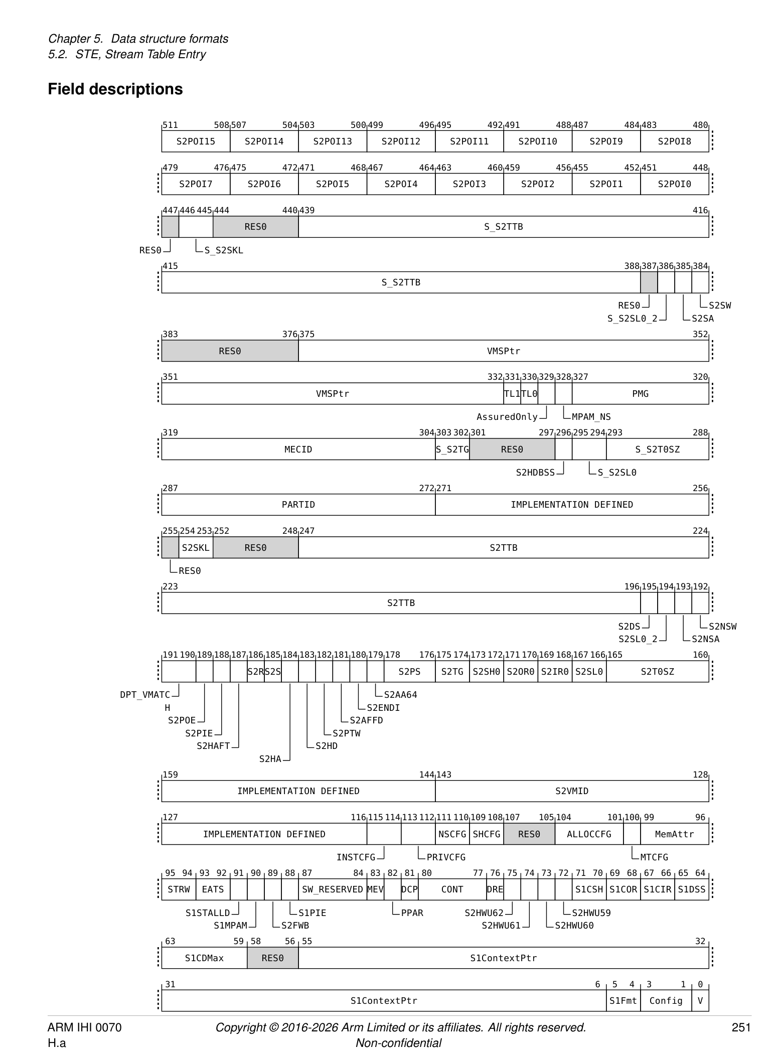
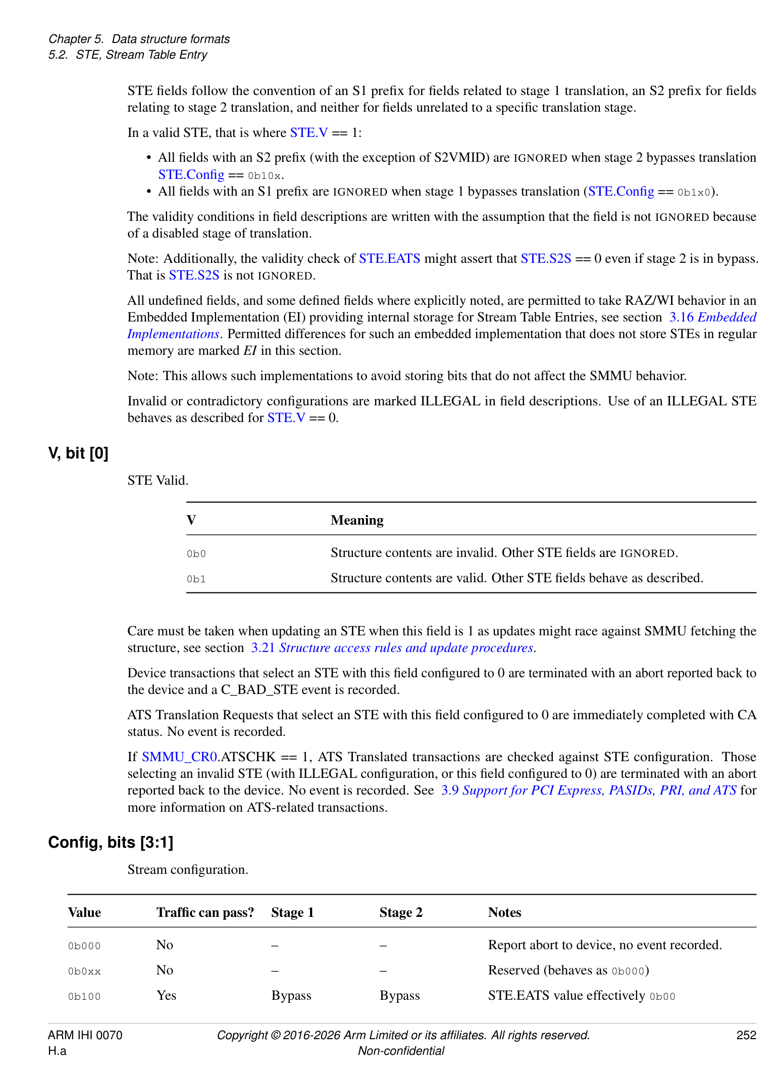
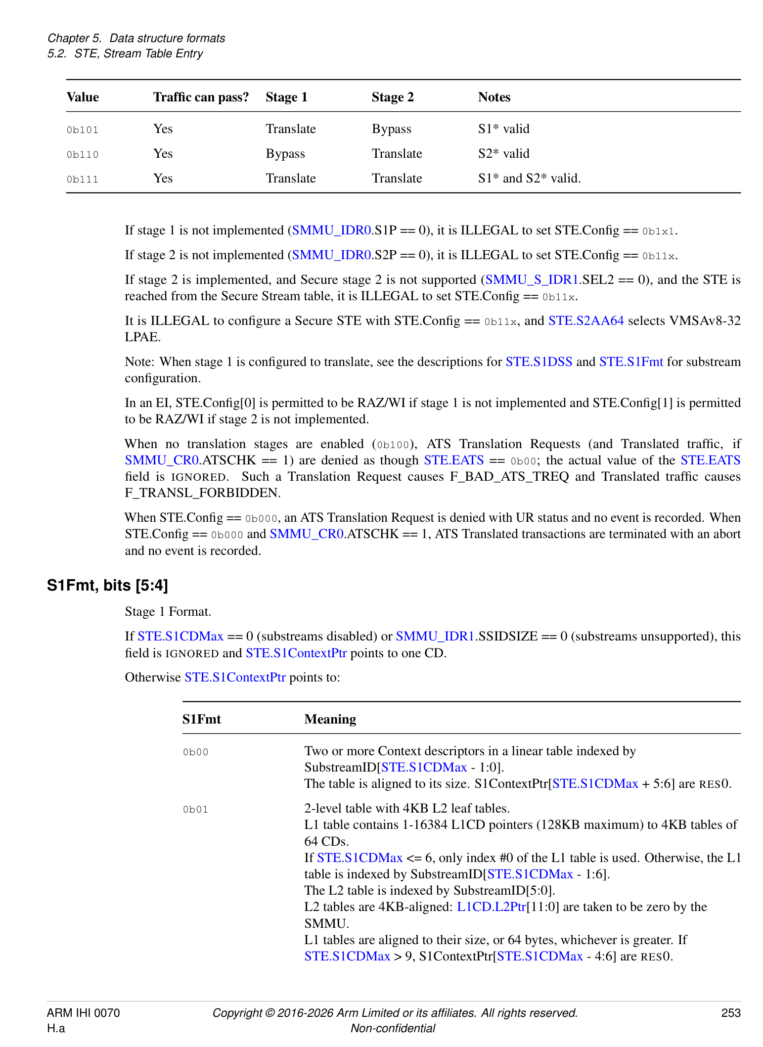
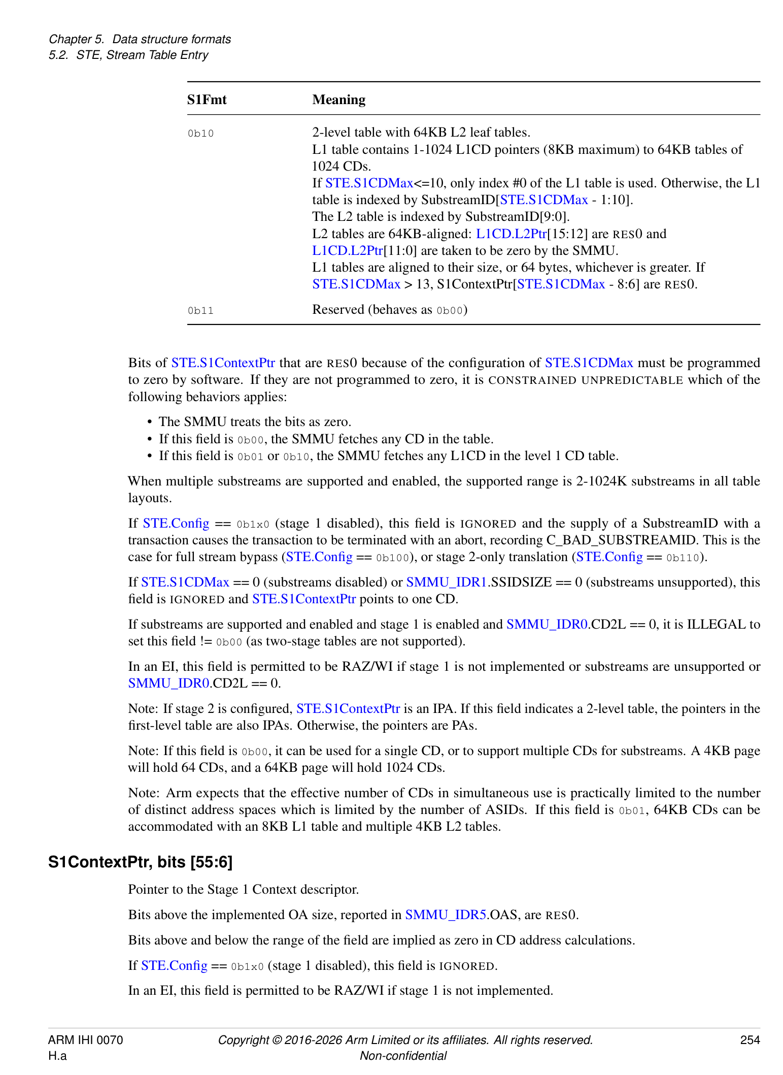
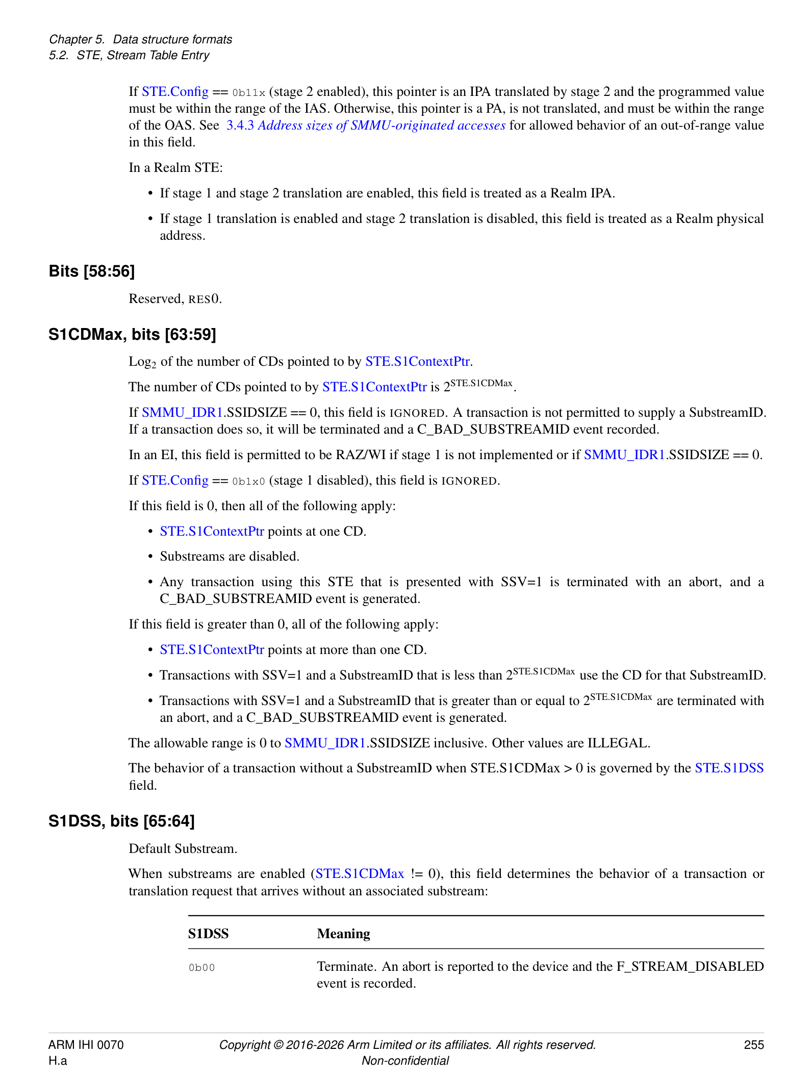
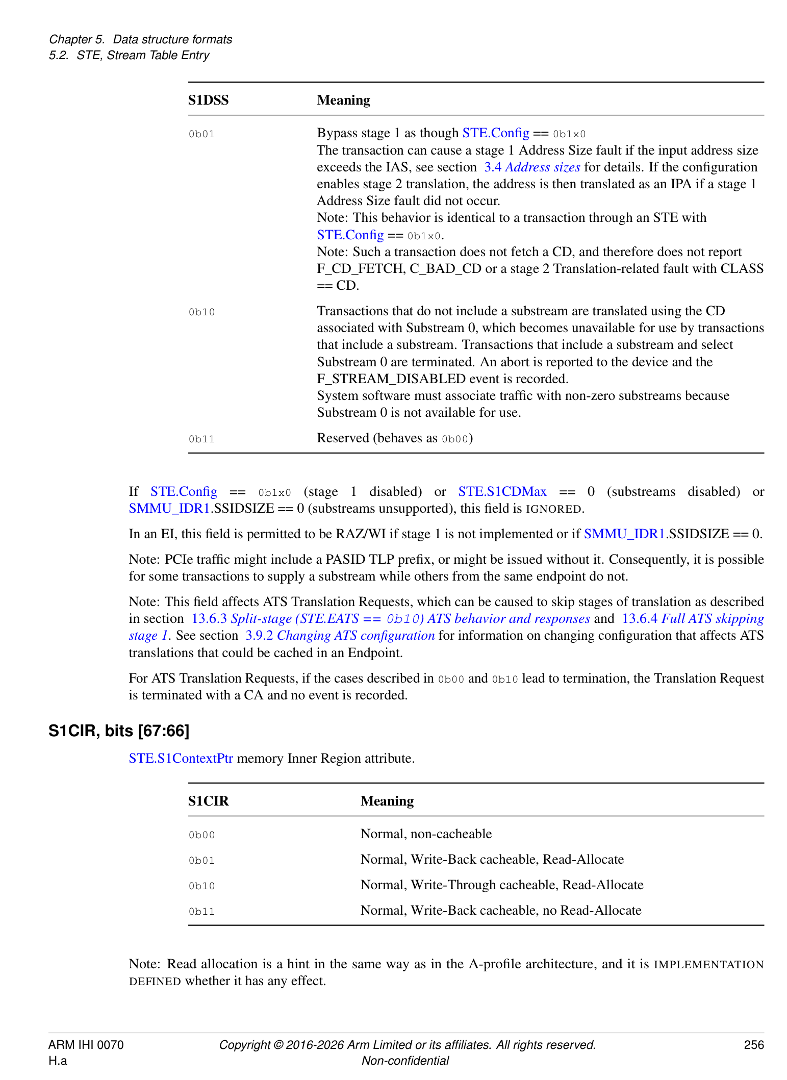
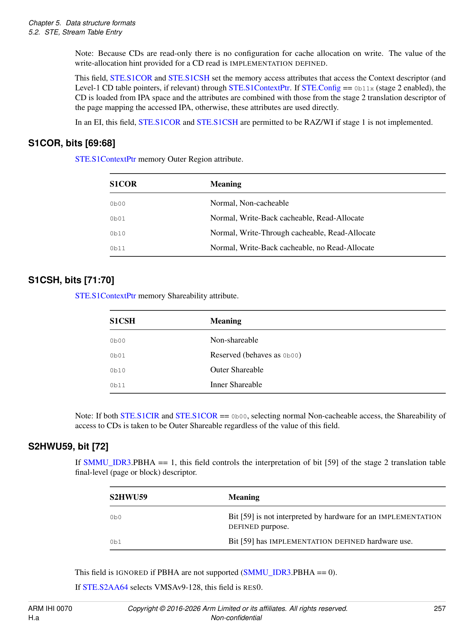
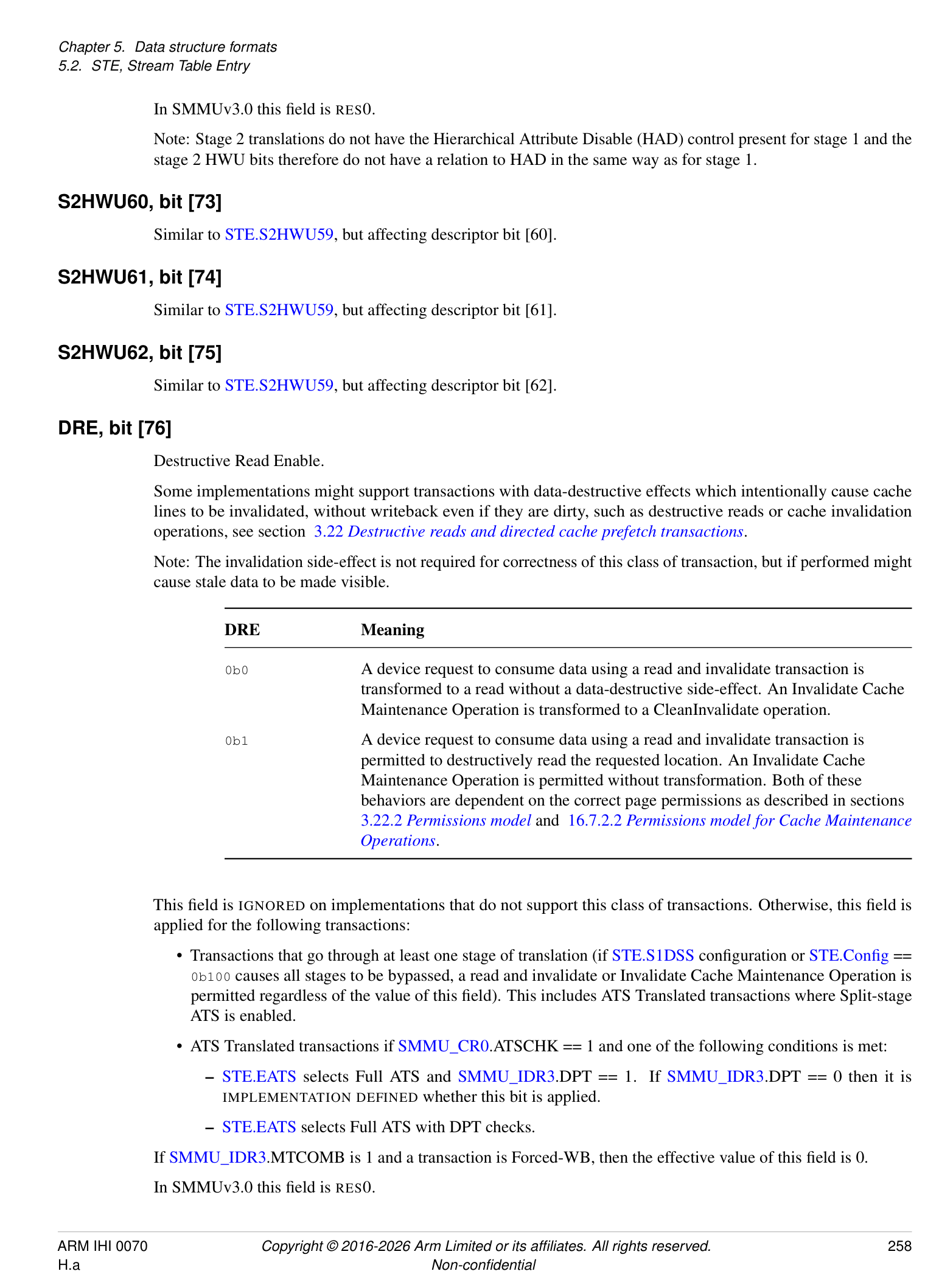
STE fields follow the convention of an S1 prefix for fields related to stage 1 translation, an S2 prefix for fields relating to stage 2 translation, and neither for fields unrelated to a specific translation stage.
In a valid STE, that is where STE.V == 1:
-
All fields with an S2 prefix (with the exception of S2VMID) are IGNORED when stage 2 bypasses translation STE.Config == 0b10x.
-
All fields with an S1 prefix are IGNORED when stage 1 bypasses translation (STE.Config == 0b1x0).
The validity conditions in field descriptions are written with the assumption that the field is not IGNORED because of a disabled stage of translation.
Note: Additionally, the validity check of STE.EATS might assert that STE.S2S == 0 even if stage 2 is in bypass. That is STE.S2S is not IGNORED.
All undefined fields, and some defined fields where explicitly noted, are permitted to take RAZ/WI behavior in an Embedded Implementation (EI) providing internal storage for Stream Table Entries, see section 3.16 Embedded Implementations . Permitted differences for such an embedded implementation that does not store STEs in regular memory are marked EI in this section.
Note: This allows such implementations to avoid storing bits that do not affect the SMMU behavior.
Invalid or contradictory configurations are marked ILLEGAL in field descriptions. Use of an ILLEGAL STE behaves as described for STE.V == 0.
V, bit [0]
STE Valid.
| V | Meaning |
|---|---|
| 0b0 | Structure contents are invalid. Other STE felds are IGNORED. |
| 0b1 | Structure contents are valid. Other STE felds behave as described. |
Care must be taken when updating an STE when this field is 1 as updates might race against SMMU fetching the structure, see section 3.21 Structure access rules and update procedures .
Device transactions that select an STE with this field configured to 0 are terminated with an abort reported back to the device and a C_BAD_STE event is recorded.
ATS Translation Requests that select an STE with this field configured to 0 are immediately completed with CA status. No event is recorded.
If SMMU_CR0.ATSCHK == 1, ATS Translated transactions are checked against STE configuration. Those selecting an invalid STE (with ILLEGAL configuration, or this field configured to 0) are terminated with an abort reported back to the device. No event is recorded. See 3.9 Support for PCI Express, PASIDs, PRI, and ATS for more information on ATS-related transactions.
Config, bits [3:1]
Stream configuration.
| Value | Traffc can pass? | Stage 1 | Stage 2 | Notes |
|---|---|---|---|---|
| 0b000 | No | – | – | Report abort to device, no event recorded. |
| 0b0xx | No | – | – | Reserved (behaves as 0b000) |
| 0b100 | Yes | Bypass | Bypass | STE.EATS value effectively 0b00 |
| Value | Traffc can pass? | Stage 1 | Stage 2 | Notes |
|---|---|---|---|---|
| 0b101 | Yes | Translate | Bypass | S1* valid |
| 0b110 | Yes | Bypass | Translate | S2* valid |
| 0b111 | Yes | Translate | Translate | S1* and S2* valid. |
If stage 1 is not implemented (SMMU_IDR0.S1P == 0), it is ILLEGAL to set STE.Config == 0b1x1.
If stage 2 is not implemented (SMMU_IDR0.S2P == 0), it is ILLEGAL to set STE.Config == 0b11x.
If stage 2 is implemented, and Secure stage 2 is not supported (SMMU_S_IDR1.SEL2 == 0), and the STE is reached from the Secure Stream table, it is ILLEGAL to set STE.Config == 0b11x.
It is ILLEGAL to configure a Secure STE with STE.Config == 0b11x, and STE.S2AA64 selects VMSAv8-32 LPAE.
Note: When stage 1 is configured to translate, see the descriptions for STE.S1DSS and STE.S1Fmt for substream configuration.
In an EI, STE.Config[0] is permitted to be RAZ/WI if stage 1 is not implemented and STE.Config[1] is permitted to be RAZ/WI if stage 2 is not implemented.
When no translation stages are enabled (0b100), ATS Translation Requests (and Translated traffic, if SMMU_CR0.ATSCHK == 1) are denied as though STE.EATS == 0b00; the actual value of the STE.EATS field is IGNORED. Such a Translation Request causes F_BAD_ATS_TREQ and Translated traffic causes F_TRANSL_FORBIDDEN.
When STE.Config == 0b000, an ATS Translation Request is denied with UR status and no event is recorded. When STE.Config == 0b000 and SMMU_CR0.ATSCHK == 1, ATS Translated transactions are terminated with an abort and no event is recorded.
S1Fmt, bits [5:4]
Stage 1 Format.
If STE.S1CDMax == 0 (substreams disabled) or SMMU_IDR1.SSIDSIZE == 0 (substreams unsupported), this field is IGNORED and STE.S1ContextPtr points to one CD.
Otherwise STE.S1ContextPtr points to:
| S1Fmt | Meaning |
|---|---|
| 0b00 | Two or more Context descriptors in a linear table indexed by |
| SubstreamID[STE.S1CDMax- 1:0]. | |
| The table is aligned to its size. S1ContextPtr[STE.S1CDMax+ 5:6] are RES0. | |
| 0b01 | 2-level table with 4KB L2 leaf tables. |
| L1 table contains 1-16384 L1CD pointers (128KB maximum) to 4KB tables of | |
| 64 CDs. | |
| IfSTE.S1CDMax<= 6, only index #0 of the L1 table is used. Otherwise, the L1 | |
| table is indexed by SubstreamID[STE.S1CDMax- 1:6]. | |
| The L2 table is indexed by SubstreamID[5:0]. | |
| L2 tables are 4KB-aligned: L1CD.L2Ptr[11:0] are taken to be zero by the | |
| SMMU. | |
| L1 tables are aligned to their size, or 64 bytes, whichever is greater. If | |
| STE.S1CDMax> 9, S1ContextPtr[STE.S1CDMax- 4:6] are RES0. |
| S1Fmt | Meaning |
|---|---|
| 0b10 | 2-level table with 64KB L2 leaf tables. |
| L1 table contains 1-1024 L1CD pointers (8KB maximum) to 64KB tables of | |
| 1024 CDs. | |
| IfSTE.S1CDMax<=10, only index #0 of the L1 table is used. Otherwise, the L1 | |
| table is indexed by SubstreamID[STE.S1CDMax- 1:10]. | |
| The L2 table is indexed by SubstreamID[9:0]. | |
| L2 tables are 64KB-aligned: L1CD.L2Ptr[15:12] are RES0 and | |
| L1CD.L2Ptr[11:0] are taken to be zero by the SMMU. | |
| L1 tables are aligned to their size, or 64 bytes, whichever is greater. If | |
| STE.S1CDMax> 13, S1ContextPtr[STE.S1CDMax- 8:6] are RES0. | |
| 0b11 | Reserved (behaves as 0b00) |
Bits of STE.S1ContextPtr that are RES0 because of the configuration of STE.S1CDMax must be programmed to zero by software. If they are not programmed to zero, it is CONSTRAINED UNPREDICTABLE which of the following behaviors applies:
-
The SMMU treats the bits as zero.
-
If this field is 0b00, the SMMU fetches any CD in the table.
-
If this field is 0b01 or 0b10, the SMMU fetches any L1CD in the level 1 CD table.
When multiple substreams are supported and enabled, the supported range is 2-1024K substreams in all table layouts.
If STE.Config == 0b1x0 (stage 1 disabled), this field is IGNORED and the supply of a SubstreamID with a transaction causes the transaction to be terminated with an abort, recording C_BAD_SUBSTREAMID. This is the case for full stream bypass (STE.Config == 0b100), or stage 2-only translation (STE.Config == 0b110).
If STE.S1CDMax == 0 (substreams disabled) or SMMU_IDR1.SSIDSIZE == 0 (substreams unsupported), this field is IGNORED and STE.S1ContextPtr points to one CD.
If substreams are supported and enabled and stage 1 is enabled and SMMU_IDR0.CD2L == 0, it is ILLEGAL to set this field != 0b00 (as two-stage tables are not supported).
In an EI, this field is permitted to be RAZ/WI if stage 1 is not implemented or substreams are unsupported or SMMU_IDR0.CD2L == 0.
Note: If stage 2 is configured, STE.S1ContextPtr is an IPA. If this field indicates a 2-level table, the pointers in the first-level table are also IPAs. Otherwise, the pointers are PAs.
Note: If this field is 0b00, it can be used for a single CD, or to support multiple CDs for substreams. A 4KB page will hold 64 CDs, and a 64KB page will hold 1024 CDs.
Note: Arm expects that the effective number of CDs in simultaneous use is practically limited to the number of distinct address spaces which is limited by the number of ASIDs. If this field is 0b01, 64KB CDs can be accommodated with an 8KB L1 table and multiple 4KB L2 tables.
S1ContextPtr, bits [55:6]
Pointer to the Stage 1 Context descriptor.
Bits above the implemented OA size, reported in SMMU_IDR5.OAS, are RES0.
Bits above and below the range of the field are implied as zero in CD address calculations.
If STE.Config == 0b1x0 (stage 1 disabled), this field is IGNORED.
In an EI, this field is permitted to be RAZ/WI if stage 1 is not implemented.
If STE.Config == 0b11x (stage 2 enabled), this pointer is an IPA translated by stage 2 and the programmed value must be within the range of the IAS. Otherwise, this pointer is a PA, is not translated, and must be within the range of the OAS. See 3.4.3 Address sizes of SMMU-originated accesses for allowed behavior of an out-of-range value in this field.
In a Realm STE:
-
If stage 1 and stage 2 translation are enabled, this field is treated as a Realm IPA.
-
If stage 1 translation is enabled and stage 2 translation is disabled, this field is treated as a Realm physical address.
Bits [58:56]
Reserved, RES0.
S1CDMax, bits [63:59]
Log2 of the number of CDs pointed to by STE.S1ContextPtr.
The number of CDs pointed to by STE.S1ContextPtr is 2[STE.S1CDMax] .
If SMMU_IDR1.SSIDSIZE == 0, this field is IGNORED. A transaction is not permitted to supply a SubstreamID. If a transaction does so, it will be terminated and a C_BAD_SUBSTREAMID event recorded.
In an EI, this field is permitted to be RAZ/WI if stage 1 is not implemented or if SMMU_IDR1.SSIDSIZE == 0.
If STE.Config == 0b1x0 (stage 1 disabled), this field is IGNORED.
If this field is 0, then all of the following apply:
-
STE.S1ContextPtr points at one CD.
-
Substreams are disabled.
-
Any transaction using this STE that is presented with SSV=1 is terminated with an abort, and a C_BAD_SUBSTREAMID event is generated.
If this field is greater than 0, all of the following apply:
-
STE.S1ContextPtr points at more than one CD.
-
Transactions with SSV=1 and a SubstreamID that is less than 2[STE.S1CDMax] use the CD for that SubstreamID.
-
Transactions with SSV=1 and a SubstreamID that is greater than or equal to 2[STE.S1CDMax] are terminated with an abort, and a C_BAD_SUBSTREAMID event is generated.
The allowable range is 0 to SMMU_IDR1.SSIDSIZE inclusive. Other values are ILLEGAL.
The behavior of a transaction without a SubstreamID when STE.S1CDMax > 0 is governed by the STE.S1DSS field.
S1DSS, bits [65:64]
Default Substream.
When substreams are enabled (STE.S1CDMax != 0), this field determines the behavior of a transaction or translation request that arrives without an associated substream:
| S1DSS | Meaning |
|---|---|
| 0b00 | Terminate. An abort is reported to the device and the F_STREAM_DISABLED |
| event is recorded. |
| S1DSS | Meaning |
|---|---|
| 0b01 | Bypass stage 1 as thoughSTE.Confg== 0b1x0 |
| The transaction can cause a stage 1 Address Size fault if the input address size | |
| exceeds the IAS, see section 3.4_Address sizes_for details. If the confguration | |
| enables stage 2 translation, the address is then translated as an IPA if a stage 1 | |
| Address Size fault did not occur. | |
| Note: This behavior is identical to a transaction through an STE with | |
| STE.Confg== 0b1x0. | |
| Note: Such a transaction does not fetch a CD, and therefore does not report | |
| F_CD_FETCH, C_BAD_CD or a stage 2 Translation-related fault with CLASS | |
| == CD. | |
| 0b10 | Transactions that do not include a substream are translated using the CD |
| associated with Substream 0, which becomes unavailable for use by transactions | |
| that include a substream. Transactions that include a substream and select | |
| Substream 0 are terminated. An abort is reported to the device and the | |
| F_STREAM_DISABLED event is recorded. | |
| System software must associate traffc with non-zero substreams because | |
| Substream 0 is not available for use. | |
| 0b11 | Reserved (behaves as 0b00) |
If STE.Config == 0b1x0 (stage 1 disabled) or STE.S1CDMax == 0 (substreams disabled) or SMMU_IDR1.SSIDSIZE == 0 (substreams unsupported), this field is IGNORED.
In an EI, this field is permitted to be RAZ/WI if stage 1 is not implemented or if SMMU_IDR1.SSIDSIZE == 0.
Note: PCIe traffic might include a PASID TLP prefix, or might be issued without it. Consequently, it is possible for some transactions to supply a substream while others from the same endpoint do not.
Note: This field affects ATS Translation Requests, which can be caused to skip stages of translation as described in section 13.6.3 Split-stage (STE.EATS == 0b10) ATS behavior and responses and 13.6.4 Full ATS skipping stage 1 . See section 3.9.2 Changing ATS configuration for information on changing configuration that affects ATS translations that could be cached in an Endpoint.
For ATS Translation Requests, if the cases described in 0b00 and 0b10 lead to termination, the Translation Request is terminated with a CA and no event is recorded.
S1CIR, bits [67:66]
STE.S1ContextPtr memory Inner Region attribute.
| S1CIR | Meaning |
|---|---|
| 0b00 | Normal, non-cacheable |
| 0b01 | Normal, Write-Back cacheable, Read-Allocate |
| 0b10 | Normal, Write-Through cacheable, Read-Allocate |
| 0b11 | Normal, Write-Back cacheable, no Read-Allocate |
Note: Read allocation is a hint in the same way as in the A-profile architecture, and it is IMPLEMENTATION DEFINED whether it has any effect.
Note: Because CDs are read-only there is no configuration for cache allocation on write. The value of the write-allocation hint provided for a CD read is IMPLEMENTATION DEFINED.
This field, STE.S1COR and STE.S1CSH set the memory access attributes that access the Context descriptor (and Level-1 CD table pointers, if relevant) through STE.S1ContextPtr. If STE.Config == 0b11x (stage 2 enabled), the CD is loaded from IPA space and the attributes are combined with those from the stage 2 translation descriptor of the page mapping the accessed IPA, otherwise, these attributes are used directly.
In an EI, this field, STE.S1COR and STE.S1CSH are permitted to be RAZ/WI if stage 1 is not implemented.
S1COR, bits [69:68]
STE.S1ContextPtr memory Outer Region attribute.
| S1COR | Meaning |
|---|---|
| 0b00 | Normal, Non-cacheable |
| 0b01 | Normal, Write-Back cacheable, Read-Allocate |
| 0b10 | Normal, Write-Through cacheable, Read-Allocate |
| 0b11 | Normal, Write-Back cacheable, no Read-Allocate |
S1CSH, bits [71:70]
STE.S1ContextPtr memory Shareability attribute.
| S1CSH | Meaning |
|---|---|
| 0b00 | Non-shareable |
| 0b01 | Reserved (behaves as 0b00) |
| 0b10 | Outer Shareable |
| 0b11 | Inner Shareable |
Note: If both STE.S1CIR and STE.S1COR == 0b00, selecting normal Non-cacheable access, the Shareability of access to CDs is taken to be Outer Shareable regardless of the value of this field.
S2HWU59, bit [72]
If SMMU_IDR3.PBHA == 1, this field controls the interpretation of bit [59] of the stage 2 translation table final-level (page or block) descriptor.
| S2HWU59 | Meaning |
|---|---|
| 0b0 | Bit [59] is not interpreted by hardware for an IMPLEMENTATION |
| DEFINEDpurpose. | |
| 0b1 | Bit [59] has IMPLEMENTATION DEFINEDhardware use. |
This field is IGNORED if PBHA are not supported (SMMU_IDR3.PBHA == 0).
If STE.S2AA64 selects VMSAv9-128, this field is RES0.
In SMMUv3.0 this field is RES0.
Note: Stage 2 translations do not have the Hierarchical Attribute Disable (HAD) control present for stage 1 and the stage 2 HWU bits therefore do not have a relation to HAD in the same way as for stage 1.
S2HWU60, bit [73]
Similar to STE.S2HWU59, but affecting descriptor bit [60].
S2HWU61, bit [74]
Similar to STE.S2HWU59, but affecting descriptor bit [61].
S2HWU62, bit [75]
Similar to STE.S2HWU59, but affecting descriptor bit [62].
DRE, bit [76]
Destructive Read Enable.
Some implementations might support transactions with data-destructive effects which intentionally cause cache lines to be invalidated, without writeback even if they are dirty, such as destructive reads or cache invalidation operations, see section 3.22 Destructive reads and directed cache prefetch transactions .
Note: The invalidation side-effect is not required for correctness of this class of transaction, but if performed might cause stale data to be made visible.
| DRE | Meaning |
|---|---|
| 0b0 | A device request to consume data using a read and invalidate transaction is |
| transformed to a read without a data-destructive side-effect. An Invalidate Cache | |
| Maintenance Operation is transformed to a CleanInvalidate operation. | |
| 0b1 | A device request to consume data using a read and invalidate transaction is |
| permitted to destructively read the requested location. An Invalidate Cache | |
| Maintenance Operation is permitted without transformation. Both of these | |
| behaviors are dependent on the correct page permissions as described in sections | |
| 3.22.2_Permissions model_and 16.7.2.2_Permissions model for Cache Maintenance_ | |
| Operations. |
This field is IGNORED on implementations that do not support this class of transactions. Otherwise, this field is applied for the following transactions:
-
Transactions that go through at least one stage of translation (if STE.S1DSS configuration or STE.Config == 0b100 causes all stages to be bypassed, a read and invalidate or Invalidate Cache Maintenance Operation is permitted regardless of the value of this field). This includes ATS Translated transactions where Split-stage ATS is enabled.
-
ATS Translated transactions if SMMU_CR0.ATSCHK == 1 and one of the following conditions is met:
-
STE.EATS selects Full ATS and SMMU_IDR3.DPT == 1. If SMMU_IDR3.DPT == 0 then it is IMPLEMENTATION DEFINED whether this bit is applied.
-
STE.EATS selects Full ATS with DPT checks.
-
If SMMU_IDR3.MTCOMB is 1 and a transaction is Forced-WB, then the effective value of this field is 0.
In SMMUv3.0 this field is RES0.
CONT, bits [80:77]
Contiguous Hint.
This field provides a hint to SMMU caching structures that a fetched STE is identical to its neighbors within a particular span of StreamIDs, and that a cache of the STE might be matched for any future lookup of StreamID for translation purposes within this span. The field is a 4-bit unsigned value specifying the span size. This field does not affect configuration invalidation. Software must ensure every STE in the required range is targeted by appropriate CMD_CFGI_* commands, regardless of the value of the field.
When CONT == 0, the STE is an individual STE bordered by STEs not considered identical. Otherwise, the span is defined as a contiguous block of 2[CONT] STEs starting at a StreamID for which StreamID[CONT-1:0]=0.
All defined fields, except for CONT, in all STEs within the stated span must be identical, otherwise the result of an STE lookup has one of the following CONSTRAINED UNPREDICTABLE behaviors:
-
The requested STE is used as it is represented in the Stream table.
-
A neighboring STE within the CONT span is used.
-
An F_CFG_CONFLICT event is reported and the transaction or translation request that led to the STE lookup is aborted.
Note: During the process of marking STEs as members of a contiguous span (or taking away such hints), the STEs might differ by their CONT field values.
Note: Arm expects that the CONT value is changed in valid STEs and that the STEs in the span are not made invalid before changing CONT. This ensures that the STEs in the span remain identical.
A span greater than the size of the Stream table is capped by the SMMU by the size of the Stream table, and does not allow StreamIDs beyond the Stream table span to match an STE.
For a given valid STE in a 2-level Stream table, if STE.CONT is configured to a range greater than the number of entries in the level 2 array that locates that STE, use of StreamIDs within the range of that STE.CONT is CONSTRAINED UNPREDICTABLE. Either one of these behaviors is permitted:
-
The transaction is terminated and a C_BAD_STREAMID error is raised, if the StreamID is outside of the range represented by the Span of the corresponding L1STD. Note: This is the expected behavior when using a StreamID outside of an L1STD.Span range.
-
The transaction uses any STE from the same Security state as the stream.
-
In an EI, this field is permitted to be RAZ/WI.
DCP, bit [81]
Directed Cache Prefetch.
Some implementations might support directed cache prefetch hint operations which are a standalone hint transaction, or a read/write transaction with hint side-effect, that changes the cache allocation in a part of the cache hierarchy that is not on the direct path to memory. This class of operation does not include those with data-destructive side-effects, see section 3.22 Destructive reads and directed cache prefetch transactions .
DCP Meaning 0b0 Directed cache prefetch operations are inhibited. A transaction input with hint side-effect is stripped of the hint. A standalone hint operation completes successfully having no effect on the system.
| DCP | Meaning |
|---|---|
| 0b1 | A directed cache prefetch operation is permitted as follows: |
| • A transaction with hint side-effect is performed if the fnal translation | |
| permissions permit the transaction. | |
| – Note: This permits a write with side-effect to progress if permissions | |
| grant write access, otherwise a Permission fault occurs. | |
| • A standalone hint operation is performed if the fnal permissions grant | |
| either read or write or execute permission for the requested address, | |
| otherwise the hint completes successfullyhavingno effect on the system. |
This field is IGNORED on implementations that do not support this class of transactions. Otherwise, this field is applied for the following transactions:
-
Transactions that go through at least one stage of translation (if STE.S1DSS configuration or STE.Config == 0b100 causes all stages to be bypassed, a directed cache prefetch is permitted regardless of the value of this field). This includes ATS Translated transactions where Split-stage ATS is enabled.
-
ATS Translated transactions if SMMU_CR0.ATSCHK == 1 and one of the following conditions is met:
-
STE.EATS selects Full ATS and SMMU_IDR3.DPT == 1. If SMMU_IDR3.DPT == 0 then it is IMPLEMENTATION DEFINED whether this bit is applied.
-
STE.EATS selects Full ATS with DPT checks.
-
In SMMUv3.0 this field is RES0.
PPAR, bit [82]
PRI Page request Auto Responses.
| PPAR | Meaning |
|---|---|
| 0b0 | Auto-generated responses on PRI queue overfow do not include a PASID |
| TLP prefx. | |
| 0b1 | Auto-generated responses on PRI queue overfow include a PASID TLP prefx |
| if permitted. |
See sections 8.1 PRI queue overflow and 8.2 Miscellaneous for the conditions that permit a PASID TLP prefix to be used on an auto-generated response.
If SMMU_IDR0.PRI == 0 or SMMU_IDR1.SSIDSIZE == 0, this field is RES0.
If SMMU_IDR3.PPS == 1, this field is IGNORED and the behavior of an auto-generated response is the same as described for PPAR == 1.
MEV, bit [83]
Merge Events arising from terminated transactions from this stream.
| MEV Meaning | |
|---|---|
| 0b0 Do not merge similar fault records 0b1 Permit similar fault records to be merged | |
The SMMU might be able to reduce the usage of the Event queue by coalescing fault records that share the same page granule of address, access type and SubstreamID.
Setting MEV == 1 does not guarantee that faults will be coalesced.
Setting MEV == 0 causes a physical SMMU to prevent coalescing of fault records, however, a hypervisor might not honour this setting if it deems a guest to be too verbose.
Note: Software must expect, and be able to deal with, coalesced fault records even when MEV == 0.
In an EI, this field is permitted to be RAZ/WI if the implementation does not merge events.
See section 7.3.1 Event record merging for details on event merging.
SWRESERVED, bits [87:84]
Reserved for software use.
This field is IGNORED by the SMMU.
In an EI, storage must be provided for this field.
S1PIE, bit [88]
Stage 1 permission indirection enable.
| S1PIE | Meaning |
|---|---|
| 0b0 | CDs fetched via this STE cannot enable stage 1 permission indirection. |
| 0b1 | CDs fetched via this STE can enable stage 1 permission indirection. |
If SMMU_IDR3.S1PI == 0 this field is RES0.
S2FWB, bit [89]
Stage 2 control of attributes.
| S2FWB | Meaning |
|---|---|
| 0b0 | Attribute calculation behaves as described in Chapter 13_Attribute_ |
| Transformation. | |
| 0b1 | Output attribute calculation and the behavior of the stage 2 page or block |
| descriptor bits [4:2] are affected as described in the VMSA in the A-profle | |
| architecture[2] for HCR_EL2.FWB == 1. |
Note: The VMSA FWB behavior allows the stage 2 memory type to be output directly instead of being combined with that of the stage 1 translation, redefining bit [4] of a stage 2 page or block descriptor to do so.
This field applies when both stage 1 and stage 2 translation is performed or when stage 2-only translation is performed. This field is IGNORED when stage 2 translation is not performed.
Otherwise, when stage 2 translation is performed, it is ILLEGAL to set this field to 1 when STE.S2AA64 selects VMSAv8-32 LPAE.
If SMMU_IDR3.MTEPERM == 1, the effects of this field on the interpretation of memory attributes change. See 3.23 Memory Tagging Extension .
Prior to SMMUv3.2 this field is RES0.
S1MPAM, bit [90]
Enable stage 1 control of MPAM.
| S1MPAM | Meaning |
|---|---|
| 0b0 | The PARTID and PMG for transactions and SMMU-originated requests relating to |
| this stream are assigned bySTE.PARTIDandSTE.PMG. | |
| 0b1 | The PARTID and PMG for transactions are assigned by theCD.PARTIDand |
| CD.PMGfelds, which might be translated using the PARTID_MAP. See section | |
| 17.2_Assignment of PARTID and PMG for client transactions_. |
Prior to SMMUv3.2, and if MPAM is not supported in the corresponding Security state, this field is RES0. Otherwise, when MPAM is supported in the corresponding Security state then:
-
When stage 1 translation is performed, this field controls whether the MPAM IDs are given by the CD or the STE. This applies to stage 1-only and nested configurations. In a nested configuration that has this field configured to 1, CD.PARTID is translated using VMS.PARTID_MAP as described in section 17.2 Assignment of PARTID and PMG for client transactions .
-
When stage 1 translation is not performed, this field is IGNORED and the STE.PARTID and STE.PMG fields are used.
- This applies to STE.Config == 0b1x0 and to scenarios where STE.S1DSS causes stage 1 to bypass.
S1STALLD, bit [91]
Stage 1 Stall Disable.
| S1STALLD | Meaning |
|---|---|
| 0b0 | Allow stalling fault model for stage 1 (confgured in CD) |
| 0b1 | Disallow stalls to be confgured for Stage 1 (faults terminate |
| immediately) |
If stage 1 is not implemented (SMMU_IDR0.S1P == 0), this field is RES0.
If stage 1 is not enabled (STE.Config == 0b1x0), this field is IGNORED.
Otherwise, if stage 1 is enabled and SMMU_(*_)IDR0.STALL_MODEL is not 0b00, it is ILLEGAL to set this field to 1 because the Stall model is not supported or not configurable.
When the Stall model is configurable, this field must be set for StreamIDs associated with stall-unsafe system topologies or for PCIe clients.
EATS, bits [93:92]
Enable PCIe ATS translation and traffic.
This field enables responses to ATS Translation Requests, and if SMMU_CR0.ATSCHK == 1, controls whether ATS Translated traffic can pass into the system.
| EATS | Meaning |
|---|---|
| 0b00 | ATS Translation Requests are returned unsuccessful or aborted (UR) and |
| F_BAD_ATS_TREQ is recorded. | |
| Additionally, ifSMMU_CR0.ATSCHK == 1, Translated traffc associated with | |
| the StreamID of the STE is prevented from bypassing the SMMU. Such traffc is | |
| terminated with an abort and a F_TRANSL_FORBIDDEN event is recorded. | |
| 0b01 | Full ATS: ATS Translation Requests are serviced by translating at all enabled |
| stages of translation. | |
| Translated traffc from the StreamID of the STE is allowed to bypass (regardless of | |
| SMMU_CR0.ATSCHK). | |
| In implementations of SMMUv3.1 and later, this confguration is ILLEGAL if this | |
| feld is not IGNOREDandSTE.Confg== 0b11xandSTE.S2S== 1. | |
| In SMMUv3.0 implementations, this confguration is ILLEGAL if this feld is not | |
| IGNOREDandSTE.S2S== 1. It is CONSTRAINED UNPREDICTABLEwhether or | |
| not this check ofSTE.S2Soccurs whenSTE.Confg== 0b10x. Arm recommends | |
| thatSTE.S2S== 1 causes STE.EATS == 0b01to be ILLEGAL only when | |
| STE.Confg== 0b11x. This condition is represented by | |
| CONSTR_UNPRED_EATS_S2Sin the pseudocode description. | |
| 0b10 | Split-stage ATS: |
| ATS Translation responses return the IPA output of stage 1 translation to the | |
| Endpoint or ATC. Subsequent Translated transactions are generated by the | |
| Endpoint with IPAs and these undergo stage 2 translation in the SMMU, see | |
| section 13.6.3_Split-stage (STE.EATS == 0b10) ATS behavior and responses_for | |
| details. | |
| This confguration must only be used when: | |
| • The stream has both stage 1 and stage 2 translation (STE.Confg== 0b111) | |
| • STE.S2S== 0 | |
| • SMMU_IDR0.NS1ATS == 0 | |
| • SMMU_CR0.ATSCHK == 1 | |
| If any of the following hold, the STE is ILLEGAL (if it is not IGNORED): | |
| • STE.Confg!= 0b111 | |
| • STE.S2S== 1. | |
| • SMMU_IDR0.NS1ATS == 1. | |
| IfSTE.Confg== 0b111andSTE.S2S== 0 andSMMU_IDR0.NS1ATS == 0, but | |
| SMMU_CR0.ATSCHK == 0 then STE.EATS == 0b10confguration behaves as | |
| 0b00. | |
| Note: See section 13.6.3_Split-stage (STE.EATS == 0b10) ATS behavior and_ | |
| _responses_and 13.6.4_Full ATS skipping stage 1_which describes interaction of this | |
| feld withSTE.S1DSS. |
| EATS | Meaning |
|---|---|
| 0b11 | Enable Full ATS with DPT checks: |
| IfSMMU_R_IDR3.DPT == 0, then this encoding is Reserved for Realm STEs | |
| and behaves as 0b00. | |
| IfSMMU_IDR3.DPT == 0, then this encoding is Reserved for Non-secure STEs | |
| and behaves as 0b00. | |
| If the correspondingSMMU_(R_)IDR3.DPT == 1 and StreamWorld is not EL1, | |
| this encoding is ILLEGAL and results in C_BAD_STE. | |
| For a Non-secure STE, if this encoding is not ILLEGAL and | |
| SMMU_CR0.ATSCHK == 0, then this encoding is treated as 0b00. | |
| This confguration is ILLEGAL if this feld is not IGNOREDandSTE.Confg== | |
| 0b11xandSTE.S2S== 1. | |
| Otherwise: | |
| Same as encoding 0b01but additionally enables per-granule checking of | |
| ATS-translated transactions. | |
| See also 3.24.1_DPT check_. |
If the STE is Secure, this field is RES0 and has an effective value of 0b00.
This field is IGNORED if any of the following hold:
-
SMMU_IDR0.ATS == 0
- ATS is not supported by the SMMU implementation. No ATS requests can be made, nor Translated traffic passed.
-
STE.Config[1:0] == 0b00
-
When STE.Config == 0b100, the effective value of this field is 0b00.The responses and events recorded for Translation Requests and Translated transactions are as described in this table for STE.EATS == 0b00.
-
When STE.Config == 0b000, Translation Requests are silently terminated with UR and, if SMMU_CR0.ATSCHK == 1, Translated transactions are silently aborted.
-
Incoming PCIe traffic marked Translated is only checked against the effective value of STE.EATS if SMMU_CR0.ATSCHK == 1, otherwise traffic marked Translated bypasses the SMMU.
Incoming ATS Translation Requests are always checked against the effective value of STE.EATS.
The behavior when STE.EATS == 0b10 or 0b11 is dependent on SMMU_CR0.ATSCHK; see section 3.9.2 Changing ATS configuration for details on changing ATS configuration. An implementation is permitted to cache ATSCHK in configuration caches, so if ATSCHK is changed while STEs exist with STE.EATS == 0b10 or 0b11 it is UNPREDICTABLE as to whether the behavior on receipt of new requests related to those STEs is as though this field is configured to 0b00 or 0b10.
In an EI, this field is permitted to be RAZ/WI if SMMU_IDR0.ATS == 0.
Note: There is no dependency between this field being non-zero and the ability for a CD to select the stall fault model with CD.S == 1. Arm expects that the Stall model is not enabled for PCIe-related streams both at stage 2 (STE.S2S == 0) and at stage 1 (CD.S == 0) and that STE.S1STALLD == 1 is used if necessary to ensure that a CD cannot use CD.S == 1 when the CD configuration is not managed the highest-privilege entity in the system. This expectation is present regardless of whether the stream uses ATS or not. If STE.S1STALLD == 0 and CD.S == 1, the Stall model might (if supported) cause PCIe traffic to stall upon fault.
STRW, bits [95:94]
StreamWorld control.
Selects the translation regime and associated Exception level controlling this stream, in conjunction with the Security state of the STE as defined by being fetched using the Stream table associated with that Security state, when stage 1 translation is used.
If stage 1 is not implemented (SMMU_IDR0.S1P == 0), this field is RES0. In this case, the effective StreamWorld is determined by STE.Config[1].
If SMMU_IDR0.Hyp == 0 and the STE is in the Non-secure Stream table this field is RES0.
If STE.Config == 0b11x (stage 2 translation enabled) and the STE is in the Non-secure or Realm Stream table, STRW is IGNORED (if it is not already RES0) and the effective StreamWorld is NS-EL1 or Realm-EL1 respectively.
If STE.Config == 0b11x and the STE is Secure and Secure stage 2 is supported, then STRW is IGNORED (if it is not already RES0) and the effective StreamWorld is Secure.
If STE.Config == 0b10x (stage 2 bypass) and STE.Config == 0b1x0 (stage 1 bypass), STRW is IGNORED (if it is not already RES0) as no translations are performed.
Note: The STRW field is not the same as the StreamWorld, which is an attribute whose Effective value might be influenced by STRW in some configurations, but not in others. See section 3.3.3 Configuration and Translation lookup for a definition of StreamWorld.
If Config == 0b101 (stage 1 only), then StreamWorld is determined from the Security state of the Stream table, STRW and SMMU_(*_)CR2.E2H as described below.
For STEs reached using the Non-secure Stream table, if STRW is not RES0 or IGNORED then StreamWorld is determined from STRW and SMMU_CR2.E2H as follows:
| STRW | E2H | Resulting StreamWorld |
|---|---|---|
| 0b00 | X | NS-EL1 |
| 0b10 | 0 | NS-EL2 |
| 0b10 | 1 | NS-EL2-E2H |
| 0bx1 | X | Reserved, ILLEGAL |
For STEs reached using the Realm Stream table, if STRW is not RES0, then StreamWorld is determined from STRW and SMMU_R_CR2.E2H as follows:
| STE.Confg | STE.STRW | Mode | Properties |
|---|---|---|---|
| 0b0xx | 0bxx | Stream disabled | See 3.10.3.2_Realm stream disabled_. |
| 0b100 | 0bxx | Stream bypass | See 3.10.3.3_Realm stream bypass_. |
| 0b101 | 0b00 | EL1 stage 1 only | Realm EL1&0 stage 1 translation, with stage 2 translation |
| disabled. | |||
| 0b101 | 0b10 | EL2 or EL2-E2H | IfSMMU_R_CR2.E2H=0 then Realm EL2 stage 1 stage 1 |
| translation. IfSMMU_R_CR2.E2H=1, then Realm EL2&0 | |||
| stage 1 translation. | |||
| 0b111 | 0bxx | EL1 stage 1 and 2 | Realm EL1&0 stage 1 translation, with stage 2 translation |
| enabled. | |||
| 0b110 | 0bxx | EL1 stage 2 only | Realm EL1&0 stage 1 translation disabled, with stage 2 |
| translation enabled. |
For STEs reached using the Secure Stream table, if STRW is not RES0 or IGNORED then StreamWorld is determined from STRW and SMMU_S_CR2.E2H as follows:
| STRW | E2H | Resulting StreamWorld | ILLEGAL when |
|---|---|---|---|
| 0b00 | X | Secure | - |
| 0b10 | 0 | S-EL2 | SMMU_S_IDR1.SEL2 == 0 |
| 0b10 | 1 | S-EL2-E2H | SMMU_S_IDR1.SEL2 == 0 |
| 0b01 | X | EL3 | SMMU_IDR0.RME_IMPL == 1 |
| 0b11 | X | Reserved, ILLEGAL | Always |
The behaviors of these StreamWorlds are as follows:
-
Secure tags TLB entries as Secure with an ASID and Arm expects this StreamWorld to be selected for Secure streams used by:
-
Secure software on an Armv7-A host PE, or Armv8-A host PE whose EL3 runs in AArch32.
-
Secure-EL1 software on an Armv8-A host PE whose EL3 runs in AArch64.
-
-
When Secure stage 2 is supported, that is SMMU_S_IDR1.SEL2 == 1, the Secure StreamWorld additionally tags TLB entries a VMID.
-
S-EL2 tags TLB entries as Secure EL2 without an ASID.
-
S-EL2-E2H tags TLB entries as Secure EL2 with an ASID, using E2H mode.
-
EL3 tags TLB entries as Secure EL3, without an ASID.
-
Note: The StreamWorld affects three things:
-
The tagging of resulting TLB entries, that is the translation regime, and ASID or VMID.
-
The number of translation tables used in the CD for stage 1.
-
The Permissions model used in stage 1 translation table
-
See also:
-
3.3.3 Configuration and Translation lookup .
-
3.3.4 Transaction attributes: incoming, two-stage translation and overrides .
MemAttr, bits [99:96]
Memory Attribute override value.
If MTCFG == 1, MemAttr provides memory type override for incoming transactions. The encoding matches the VMSAv8-64 stage 2 MemAttr[3:0] field as described in the A-profile architecture[2], except that the following encodings are Reserved (not UNPREDICTABLE) and behave as Device-nGnRnE:
-
0b0100
-
0b1000
-
0b1100
Note: In the A-profile architecture[2], FEAT_MTE_PERM introduces the encoding 0b0100 for the stage 2 MemAttr[3:0] field. This behavior is implemented in the SMMU if SMMU_IDR3.MTEPERM == 1. For STE.MemAttr this encoding remains Reserved and behaves as Device-nGnRnE. See section 3.23.1 SMMU support for FEAT_MTE_PERM .
Note: This encoding matches the encoding of the stage 2 translation table descriptor MemAttr field that is used when S2FWB == 0. The S2FWB field only affects the stage 2 translation table descriptor MemAttr field, and does not affect the encoding of this field.
If MTCFG == 0 or SMMU_IDR1.ATTR_TYPES_OVR == 0, this field is RES0.
MTCFG, bit [100]
Memory Type configuration.
| MTCFG | Meaning |
|---|---|
| 0b0 | Use incoming type or Cacheability |
| 0b1 | Replace incoming type or Cacheability with that defned by MemAttr |
| feld |
If SMMU_IDR1.ATTR_TYPES_OVR == 0, this field is RES0 and the incoming Memory Type is used.
When SMMU_IDR3.MTCOMB is 0, it is IMPLEMENTATION DEFINED whether MTCFG applies to streams associated with PCIe devices or whether the incoming Memory Type is used for such streams regardless of the field value.
ALLOCCFG, bits [104:101]
Allocation hints override.
-
0b0xxx: Use incoming RA, WA, TR hints
-
0b1RWT: Hints are overridden to given values:
-
Read Allocate == R
-
Write Allocate == W
-
Transient == T
-
When overridden by this field, for each of RA/WA and TR, both inner and outer hints are set to the same value. Because it is not architecturally possible to express hints for types that are any-Device or Normal-Non-cacheable, this field has no effect on memory types that are not Normal-WB or Normal-WT, whether such types are provided with transaction from the client device or overridden using MTCFG/MemAttr.
Note: A value of 0b1001 encodes Transient with no-allocate. When the SMMU ensures output attribute consistency (see section 13.1.7 Ensuring consistent output attributes ), no-allocate is considered to be non-transient. As there is no value of stage 1/stage 2 attribute with which Transient-no-allocate could combine to cause an allocating Transient attribute to be output, 0b1001 is functionally equivalent to 0b1000 (non-Transient, no-allocate).
If SMMU_IDR1.ATTR_TYPES_OVR == 0, this field is RES0 and the incoming Allocation hints are used.
When SMMU_IDR3.MTCOMB is 0, it is IMPLEMENTATION DEFINED whether ALLOCCFG applies to streams associated with PCIe devices or whether the incoming allocation hints are used for such streams regardless of the field value.
When SMMU_IDR3.MTCOMB is 0 and STE.MTCFG is 0, it is CONSTRAINED UNPREDICTABLE whether ALLOCCFG has any effect on the allocation hints for the cacheability domains of a transaction.
Bits [107:105]
Reserved, RES0.
SHCFG, bits [109:108]
Shareability configuration.
| SHCFG | Meaning |
|---|---|
| 0b00 | Non-shareable |
| 0b01 | Use incoming Shareability attribute |
| 0b10 | Outer shareable |
| 0b11 | Inner shareable |
Architecturally, any-Device and Normal-iNC-oNC are OSH and Shareability is only variable where cacheable types are used. This field has no effect on memory types that do not contain Normal-{i,o}WB or Normal-{i,o}WT, whether such types are provided with transaction from the client device or overridden using MTCFG/MemAttr.
If SMMU_IDR1.ATTR_TYPES_OVR == 0, this field is RES0 and the incoming Shareability attribute is used.
When SMMU_IDR3.MTCOMB is 0, it is IMPLEMENTATION DEFINED whether SHCFG applies to streams associated with PCIe devices or whether the incoming Shareability attribute is used for such streams regardless of the field value.
NSCFG, bits [111:110]
Non-secure attribute configuration.
For a Secure stream, NSCFG is interpreted as follows:
| NSCFG | Meaning |
|---|---|
| 0b00 | Use incoming NS attribute |
| 0b01 | Reserved, behaves as 0b00. |
| 0b10 | Secure |
| 0b11 | Non-secure |
NSCFG is IGNORED when the STE is in the Non-secure Stream table.
NSCFG is IGNORED when the STE is in the Secure Stream table and stage 1 translation is enabled. In this case the final NS attribute is determined entirely by the translation process (see CD.NSCFGx, the TTD.NSTable and TTD.NS bits). The input NS attribute and this field are not used. If Secure stage 2 is enabled, the output IPA space determined from the stage 1 translation is input into stage 2. See section 3.10.2.2 Secure EL2 and support for Secure stage 2 translation .
Otherwise, when the STE is in the Secure Stream table and stage 1 translation is disabled (STE.Config == 0b1x0):
-
If SMMU_IDR1.ATTR_PERMS_OVR == 0, this field is RES0 and the incoming NS attribute is output from stage 1 directly. If Secure stage 2 is enabled, the NS attribute is input into stage 2 and selects between the Secure and Non-secure IPA spaces.
-
If SMMU_IDR1.ATTR_PERMS_OVR == 1, this field determines the target IPA or PA space of transactions that bypass stage 1 translation and this value is output from stage 1 as the target IPA or PA space.
- Note: Arm recommends that SMMU_IDR1.ATTR_PERMS_OVR == 1 if an implementation might be used in a system where the input NS attribute from a client device on a Secure stream is not accurate, and is required to be overridden by the SMMU configuration.
-
If Secure stage 2 is enabled, the resulting NS attribute is input into stage 2. See section 3.10.2.2 Secure EL2 and support for Secure stage 2 translation .
Note: The function of this field is not related to the CD.NSCFG{0,1} fields (whose purpose is to affect the NS property of the translation table walk).
For a Realm stream, NSCFG is interpreted as follows:
| Value | Meaning |
|---|---|
| 0b00 | Use incoming NS attribute. |
| 0b01 | IfSMMU_R_IDR3.XT == 0, then Reserved, behaves as 0b00. IfSMMU_R_IDR3.XT == 1, then Check |
| incoming NS attribute. | |
| 0b10 | Override to Realm. |
| 0b11 | Override to Non-secure. |
Note: If the Realm client device does not provide an input NS attribute, the input NS attribute defaults to Realm.
Note: NSCFG is supported for Realm streams regardless of the value of SMMU_IDR1.ATTR_PERMS_OVR.
PRIVCFG, bits [113:112]
User/privileged attribute configuration.
| PRIVCFG | Meaning |
|---|---|
| 0b00 | Use incoming PRIV attribute |
| 0b01 | Reserved, behaves as 0b00. |
| 0b10 | Unprivileged |
| 0b11 | Privileged |
If SMMU_IDR1.ATTR_PERMS_OVR == 0, this field is RES0 and the incoming PRIV attribute is used.
INSTCFG, bits [115:114]
Inst/Data attribute configuration.
| INSTCFG | Meaning |
|---|---|
| 0b00 | Use incoming INST attribute |
| 0b01 | Reserved, behaves as 0b00. |
| 0b10 | Data |
| 0b11 | Instruction |
If SMMU_IDR1.ATTR_PERMS_OVR == 0, this field is RES0 and the incoming INST attribute is used.
INSTCFG only affects translations for reads, the SMMU considers incoming writes to be Data regardless of this field. See section 13.1.2 Attribute support .
IMPLEMENTATION DEFINED, bits [127:116]
IMPLEMENTATION DEFINED per-stream configuration. (For example, QoS overrides for configuration access, data streams.)
S2VMID, bits [143:128]
Virtual Machine Identifier
Marks TLB entries inserted because of translations located through this STE, differentiating them from translations belonging to different virtual machines.
For a Non-secure STE when stage 2 is implemented (SMMU_IDR0.S2P == 1) translations resulting from a StreamWorld == NS-EL1 configuration are VMID-tagged with STE.S2VMID when either of stage 1 (STE.Config == 0b1x1) or stage 2 (STE.Config == 0b11x) provide translation.
For a Secure STE when Secure stage 2 is implemented, that is SMMU_S_IDR1.SEL2 == 1, and when StreamWorld == Secure:
-
Translations are VMID-tagged with STE.S2VMID when stage 2 is enabled (STE.Config == 0b11x), including nested configuration.
-
When only stage 1 is enabled, this field is IGNORED and translations are tagged with VMID 0.
Note: Secure VMIDs and Non-secure VMIDs are different namespaces. See section 3.10.2.2 Secure EL2 and support for Secure stage 2 translation .
When an implementation supports only 8-bit VMIDs, that is when SMMU_IDR0.VMID16 == 0, it is ILLEGAL for bits STE.S2VMID[15:8] to be non-zero unless this field is IGNORED.
STE.S2VMID[15:0] is IGNORED and no VMID tagging occurs when any of the following are true:
-
Stage 2 is not implemented in the Security state corresponding to the STE.
-
STE.Config[1:0] == 0b00. Note: In this case, no TLB entries are inserted as translation is bypassed.
-
A Non-secure STE StreamWorld is not NS-EL1.
-
A Secure STE has a StreamWorld other than “Secure”.
-
A Realm STE StreamWorld is not Realm-EL1.
Note: If SMMU_IDR0.S2P == 0, then for broadcast TLB maintenance, the SMMU is only required to invalidate Non-secure EL1 or Secure StreamWorld TLB entries if VMID is 0 in the broadcast TLB maintenance operation. See 3.17 TLB tagging, VMIDs, ASIDs and participation in broadcast TLB maintenance .
In an EI, this field is permitted to be RAZ/WI if stage 2 is not implemented. In an EI implementing stage 2 with 8-bit VMIDs, STE.S2VMID[15:8] are permitted to be RAZ/WI.
If 16-bit VMIDs are supported by an implementation, the full VMID[15:0] value is used regardless of STE.S2AA64. Arm expects that legacy and AArch32 hypervisor software using 8-bit VMIDs will write zero-extended 8-bit values in the VMID field in this case.
See section 3.17 TLB tagging, VMIDs, ASIDs and participation in broadcast TLB maintenance for more information on ASID and VMID TLB tagging.
Changes to the STE.S2VMID field of an STE are not automatically reflected in cached translations, which must be subjected to separate TLB maintenance.
Note: This field might be supplied by an implementation in transactions to the memory system for IMPLEMENTATION DEFINED purposes.
IMPLEMENTATION DEFINED, bits [159:144]
IMPLEMENTATION DEFINED.
S2T0SZ, bits [165:160]
Size of IPA input region covered by stage 2 translation table.
This field is equivalent to VTCR_EL2.T0SZ in the A-profile architecture[2].
This field is 4 bits ([3:0]) and bits [5:4] are IGNORED when stage 2 translation is VMSAv8-32 LPAE, as indicated by STE.S2AA64. The input region size is calculated the same as in the A-profile architecture[2]. When STE.S2AA64 selects VMSAv8-64 or VMSAv9-128, this field is 6 bits and the region size is calculated the same as for VTCR_EL2 in the A-profile architecture[2].
If stage 2 translation is enabled (STE.Config == 0b11x), legal values of STE.S2SL0 and STE.S2TG relate to this field as defined by the Translation system in the A-profile architecture[2], in section D5.2.3, “Controlling Address translation stages”.
Note: This field is IGNORED when stage 2 is implemented but not enabled (STE.Config == 0b10x).
When STE.S2AA64 selects VMSAv8-64:
-
If SMMU_IDR3.STT == 0, the maximum valid value is 39.
-
If SMMU_IDR3.STT == 1, the maximum valid value is:
-
48, when STE.S2TG selects a 4KB or 16KB granule
-
47, when STE.S2TG selects a 64KB granule.
-
-
In SMMUv3.0, the minimum valid value for this field is (64-IAS).
-
In architectures after SMMUv3.0:
- If STE.S2TG selects a 4KB or 16KB granule and STE.S2DS == 0, the minimum valid value for this field is MAX(16, 64-IAS).
-
Otherwise, the minimum valid value for this field is MAX(12, 64-IAS).
When STE.S2AA64 selects VMSAv9-128:
-
The maximum valid value is:
-
48, when STE.S2TG selects a 4KB or 16KB granule.
-
47, when STE.S2TG selects a 64KB granule.
-
-
The minimum valid value is MAX(8, 64-IAS).
Note: see section 3.4 Address sizes for restrictions on IAS.
When STE.S2AA64 selects VMSAv8-32 LPAE, this field encodes a value from -8 to 7 as defined by the Translation system in the A-profile architecture[2].
Note: When STE.S2AA64 selects VMSAv8-32 LPAE all 4-bit values are valid, therefore it is not possible to use a value outside the valid range but it is still possible for this field to be inconsistent with STE.S2SL0.
In SMMUv3.0 implementations, the use of a value out of range of these maximum and minimum valid values is CONSTRAINED UNPREDICTABLE and has one of the following behaviors:
-
The STE becomes ILLEGAL.
-
The STE is not ILLEGAL and the effective value used by the translation is the maximum permitted value (if the programmed value is greater than the maximum permitted value) or the minimum permitted value (if the programmed value is less than the minimum permitted value).
Note: This condition is represented by constr_unpred_S2T0SZ_oor_ILLEGAL in the pseudocode description.
In implementations of SMMUv3.1 and later, an STE is treated as ILLEGAL if it contains a STE.S2T0SZ value out of range of these maximum and minimum values.
The usable range of values is further constrained by a function of the starting level set by STE.S2SL0 and, if STE.S2AA64 selects VMSAv8-64 or VMSAv8-32 LPAE, granule size set by STE.S2TG as described by the translation system in the A-profile architecture[2]. Use of a value of STE.S2T0SZ that is inconsistent with the permitted range (given STE.S2SL0 and STE.S2TG) is ILLEGAL.
Note: The SMMU behavior differs from the Translation system in the A-profile architecture[2], in which the legal range of VTCR_EL2.T0SZ values can also depend on whether EL1&0 stage 1 uses VMSAv8-32 LPAE or VMSAv8-64.
If stage 2 is not implemented, that is if SMMU_IDR0.S2P == 0, this field is RES0.
S2SL0, bits [167:166]
Starting level of stage 2 translation table walk.
If STE.S2DS == 1 and STE.S2TG selects 4KB, this field is considered in combination with the STE.S2SL0_2 field.
The stage 2 walk start level is a function of STE.{S2SL0_2, S2SL0} and the value of STE.S2TG.
When STE.S2AA64 selects VMSAv8-64, the encoding of STE.{S2SL0_2, S2SL0} is the same as for the VTCR_EL2.{SL2, SL0} fields in the A-profile architecture[2].
When STE.S2AA64 selects VMSAv8-32 LPAE, the encoding of this field is the same as for the VTCR.SL0 field in the A-profile architecture[2].
If stage 2 is not implemented, that is if SMMU_IDR0.S2P == 0, this field is RES0.
If stage 2 translation is enabled (STE.Config == 0b11x), it is ILLEGAL for the configuration of STE.{S2SL0_2, S2SL0} to be inconsistent with STE.S2T0SZ and STE.S2TG.
If STE.S2AA64 selects VMSAv9-128, this field is RES0.
S2IR0, bits [169:168]
Inner region Cacheability for stage 2 translation table access.
| S2IR0 | Meaning |
|---|---|
| 0b00 | Non-cacheable |
| 0b01 | Write-back Cacheable, Read-Allocate, Write-Allocate |
| 0b10 | Write-through cacheable, Read-Allocate |
| 0b11 | Write-back cacheable, Read-Allocate, no Write-Allocate |
The only time that translation table entries are written by the SMMU is when HTTU is in use, and because the read effect of the atomic update might cause read allocation of the affected translation table entry into a data cache, it is IMPLEMENTATION DEFINED as to whether 0b01 and 0b11 differ.
Many memory systems might require use of Normal Write-back Cacheable memory for the atomic updates of translation table entries to occur correctly.
If HTTU is enabled and this field is configured to 0b00 or 0b10, then it is IMPLEMENTATION DEFINED which of the following behaviors occurs for hardware updates of Access flag and dirty state:
-
The hardware update occurs correctly as an atomic read-modify-write operation.
-
The hardware update occurs, but the read-modify-write operation is not guaranteed to be atomic.
-
The hardware update is attempted but fails and generates an F_WALK_EABT event.
Arm recommends that software uses 0b01 or 0b11 when HTTU is enabled for this translation table unless the behavior of an implementation is otherwise known.
If stage 2 is not implemented, that is if SMMU_IDR0.S2P == 0, this field is RES0.
S2OR0, bits [171:170]
Outer region Cacheability for stage 2 translation table access.
Same as for S2IR0.
S2SH0, bits [173:172]
Shareability for stage 2 translation table access.
| S2SH0 | Meaning |
|---|---|
| 0b00 | Non-shareable |
| 0b01 | Reserved, behaves as 0b00. |
| 0b10 | Outer Shareable |
| 0b11 | Inner Shareable |
Note: If both S2IR0 and S2OR0 == 0b00, selecting normal Non-cacheable access, the Shareability of translation table access is taken to be OSH regardless of the value of this field.
If stage 2 is not implemented, that is if SMMU_IDR0.S2P == 0, this field is RES0.
S2TG, bits [175:174]
Stage 2 Translation Granule size.
| S2TG | Meaning |
|---|---|
| 0b00 | 4KB |
| 0b01 | 64KB |
| 0b10 | 16KB |
| 0b11 | Reserved |
If stage 2 is not implemented, that is when SMMU_IDR0.S2P == 0, this field is RES0.
Otherwise, if stage 2 translation is disabled (STE.Config == 0b10x), this field is IGNORED.
Otherwise, if stage 2 translation is enabled (STE.Config == 0b11x),
-
If STE.S2AA64 selects VMSAv8-32 LPAE, this field is RES0 and the effective value of this field is 4KB.
-
If STE.S2AA64 selects VMSAv8-64 or VMSAv9-128, this field must only select a granule supported by the SMMU, as described in SMMU_IDR5, and use of an unsupported size or Reserved value is ILLEGAL.
-
It is ILLEGAL for STE.S2T0SZ and STE.S2SL0 to be inconsistent with the value of this field, as described in the A-profile architecture[2].
S2PS, bits [178:176]
Physical address Size.
This field is equivalent to VTCR_EL2.PS in the A-profile architecture[2].
| S2PS | Meaning |
|---|---|
| 0b000 | 32 bits |
| 0b001 | 36 bits |
| 0b010 | 40 bits |
| 0b011 | 42 bits |
| 0b100 | 44 bits |
| 0b101 | 48 bits |
| 0b110 | 52 bits |
| In SMMUv3.0 implementations, this value is Reserved and behaves as | |
| 0b101. | |
| 0b111 | 56 bits. |
| In SMMUv3.0 implementations, this value is Reserved and behaves as | |
| 0b101. | |
| In implementations of SMMUv3.1 to SMMUv3.3, this value is Reserved | |
| and behaves as 0b110. |
Software must not rely on the behavior of Reserved values.
This field determines the Physical address size for the purpose of Address Size fault checking the output of stage 2 translation, see section 3.4 Address sizes .
If stage 2 is not implemented, that is when SMMU_IDR0.S2P == 0, this field is RES0.
If STE.S2AA64 selects VMSAv8-32 LPAE, this field is IGNORED and the effective stage 2 output address size is taken as 40 bits.
If STE.S2AA64 selects VMSAv8-64 or VMSAv9-128, the effective stage 2 output address size is given by:
eff_S2PS = MIN(S2PS, SMMU_IDR5.OAS);
The effective value of this field is capped to the OAS.
When STE.S2AA64 selects VMSAv8-64 or VMSAv9-128, setting this field to any value greater than the cap defined here behaves as though this field equals the cap size. Software must not rely on this behavior.
Note: This includes use of a Reserved value.
An Address Size fault occurs if stage 2 translation outputs an address that has non-zero bits above eff_S2PS .
If STE.S2AA64 selects VMSAv8-64, an address of 52 bits in size can be output from stage 2 when eff_S2PS is 52 and either:
-
64KB granule is in use for that translation table.
-
STE.S2DS == 1.
An address of 56 bits in size can be output from stage 2 when STE.S2AA64 selects VMSAv9-128.
Note: In configurations where eff_S2PS is larger than the address output from the stage 2 descriptor, output bits above the address are treated as zero and no Address Size fault can occur.
In SMMUv3.0 addresses are limited to 48 bits.
S2AA64, bit [179]
Stage 2 translation table format for S2TTB0, and S_S2TTB0 if appropriate.
| S2AA64 | Meaning | Applies when |
|---|---|---|
| 0b0 | Use VMSAv8-32 LPAE | SMMU_IDR0.TTF[0] == 1 |
| descriptor formats. | ||
| 0b0 | Use VMSAv9-128 descriptor | SMMU_IDR5.D128 == 1 |
| formats. | ||
| 0b1 | Use VMSAv8-64 descriptor | |
| formats. |
If stage 2 is not implemented, that is when SMMU_IDR0.S2P == 0, this field is RES0.
If SMMU_IDR5.D128 == 0 and stage 2 translation is enabled (STE.Config == 0b11x), it is ILLEGAL to select:
-
VMSAv8-32 LPAE tables when VMSAv8-32 LPAE tables are not supported (SMMU_IDR0.TTF[0] == 0).
-
VMSAv8-64 tables when VMSAv8-64 tables are not supported (SMMU_IDR0.TTF[1] == 0).
If an STE is in the Secure stream table and STE.Config == 0b11x, it is ILLEGAL to select VMSAv8-32 LPAE.
If this field selects VMSAv9-128, then STE.{S2SL0, S2SL0_2, S_S2SL0, S_S2SL0_2} fields are all RES0. If SMMU_IDR5.D128 == 1, the behavior of this field is equivalent to VTCR_EL2.D128 in the A-profile architecture[2], with reversed polarity.
Note: The stage 2 translation table permissions are interpreted slightly differently between VMSAv8-64 and VMSAv8-32 LPAE format tables, for example, a VMSAv8-64 stage 2 table can encode an execute-only page permission whereas a VMSAv8-32 LPAE stage 2 table cannot, see the A-profile architecture[2] for more information.
This field is permitted to be cached in a TLB.
S2ENDI, bit [180]
Stage 2 translation table endianness.
| S2ENDI | Meaning |
|---|---|
| 0b0 | Little Endian |
| 0b1 | Big Endian |
If Stage 2 translation is enabled (STE.Config == 0b11x), it is ILLEGAL for this field to select an unimplemented endianness (as indicated by SMMU_IDR0.TTENDIAN).
If stage 2 is not implemented, that is when SMMU_IDR0.S2P == 0, this field is RES0.
S2AFFD, bit [181]
Stage 2 Access Flag Fault Disable.
When HTTU is not in use at stage 2 because (STE.S2HA == 0 or HTTU is not supported, this flag determines the behavior on access of a stage 2 page whose descriptor has AF == 0:
| S2AFFD | Meaning |
|---|---|
| 0b0 | An Access fag fault occurs (behavior controlled bySTE.S2R |
| andSTE.S2Sbits) |
| S2AFFD | Meaning |
|---|---|
| 0b1 | An Access fag fault never occurs; the TTD.AF bit is |
| considered to be always 1. |
When (STE.S2HA == 1, this flag is IGNORED.
If stage 2 is not implemented, that is if SMMU_IDR0.S2P == 0, this field is RES0.
S2PTW, bit [182]
Protected Table Walk.
For an STE configured for translation at both stages, a stage 1 translation table walk access or CD fetch access made to a stage 2 page with any Device type is terminated and recorded as a stage 2 Permission fault if this field is set.
Note: This might provide early indication of a programming error.
| S2PTW | Meaning |
|---|---|
| 0b0 | IfSMMU_IDR3.PTWNNC == 0: CD fetch and stage 1 translation table walks |
| allowed to any valid stage 2 address. | |
| IfSMMU_IDR3.PTWNNC == 1: A translation table access or CD fetch | |
| mapped as any Device type occurs as if it is to Normal Non-cacheable memory. | |
| 0b1 | CD fetch or Stage 1 translation table walks to stage 2 addresses mapped as any |
| Device are terminated. A stage 2 Permission fault is recorded. |
If STE.Config[1:0] != 0b11, this field is IGNORED.
If stage 2 is not implemented, that is if SMMU_IDR0.S2P == 0, this field is RES0.
S2HD, bit [183]
Hardware Translation Table Update of stage 2 Dirty flags.
See definition of S2HA.
S2HA, bit [184]
Hardware Translation Table Update of stage 2 Access flags.
When combined with STE.S2HD as {STE.S2HA, STE.S2HD}:
-
0b00: HTTU disabled
-
0b10: Update of Access flag enabled
-
0b01: Reserved. If STE.S2HD == 1 is not ILLEGAL, behaves as (STE.S2HA == 0 and STE.S2HD == 0).
-
0b11: Update of Access flag and dirty state of the page enabled
If stage 2 translation is enabled (STE.Config == 0b11x),
-
It is ILLEGAL to set STE.S2HA or (STE.S2HD if STE.S2AA64 selects VMSAv8-32 LPAE.
-
It is ILLEGAL to set STE.S2HA if SMMU_IDR0.HTTU == 0b00.
-
It is ILLEGAL to set STE.S2HD if SMMU_IDR0.HTTU == 0b00 or 0b01.
These fields are RES0 if stage 2 is not implemented. In an EI, this field is permitted to be RAZ/WI if stage 2 is not implemented or SMMU_IDR0.HTTU == 0b00. In an EI, STE.S2HD is permitted to be RAZ/WI if stage 2 is not implemented or SMMU_IDR0.HTTU == 0b0x.
Note: If HTTU is enabled when S2OR0 or S2IR0 indicate Non-cacheable memory, behavior is IMPLEMENTATION DEFINED, see 3.15 Coherency considerations and memory access types . A system might only be able to perform atomic updates using cacheable normal memory, or might implement other means for doing so.
S2S, bit [185]
Stage 2 fault behavior - Stall.
See section 5.5 Fault configuration (A, R, S bits) for a description of fault configuration.
When STE.Config == 0b10x (Stage 2 disabled), {S2R, S2S} are IGNORED.
If stage 2 is not implemented, that is when SMMU_IDR0.S2P == 0, this field is RES0.
For accesses with PM = 1, this field is treated as 0 for all purposes other than STE validity checks.
S2R, bit [186]
Stage 2 fault behavior - Record.
See section 5.5 Fault configuration (A, R, S bits) for a description of fault configuration.
When STE.Config == 0b10x (Stage 2 disabled), {S2R, S2S} are IGNORED.
If stage 2 is not implemented, that is when SMMU_IDR0.S2P == 0, this field is RES0.
S2HAFT, bit [187]
Enable hardware update of Access flag in Table descriptors.
| S2HAFT | Meaning |
|---|---|
| 0b0 | Stage 2 HAFT disabled. |
| 0b1 | Stage 2 HAFT enabled. |
If STE.S2HA is 0 and not IGNORED, it is ILLEGAL to set this field to 1 and this results in C_BAD_STE. This field is permitted to be cached in a TLB.
If SMMU_IDR0.HTTU != 0b11 this field is RES0.
S2PIE, bit [188]
Stage 2 permissions indirection enable.
This field is equivalent to VCTR_EL2.S2PIE in the A-profile architecture[2].
| S2PIE | Meaning |
|---|---|
| 0b0 | Stage 2 translations use the Direct Permission Scheme. |
| 0b1 | Stage 2 translations use the Indirect Permission Scheme. |
Note: For each Security state, this field must be configured consistently for all STEs that have the same value of STE.S2VMID.
If STE.S2AA64 selects VMSAv9-128, this field is RES0 and stage 2 translations use the Indirect Permission Scheme.
If SMMU_IDR3.S2PI == 0 or STE.S2AA64 selects VMSAv8-32 this field is RES0.
This field is permitted to be cached in a TLB.
S2POE, bit [189]
Stage 2 permission overlay enable.
This field is similar to VCTR_EL2.S2POE in the A-profile architecture[2].
| S2POE | Meaning |
|---|---|
| 0b0 | Do not apply stage 2 overlay permissions. |
| 0b1 | Apply stage 2 overlay permissions. |
If stage 2 translations use the Direct Permission Scheme, it is ILLEGAL to set this field to 1 and this results in C_BAD_STE.
If any of STE.{S2HWU62, S2HWU61, S2HWU60, S2HWU59} are 1, it is ILLEGAL to set this field to 1 and this results in C_BAD_STE.
This field is permitted to be cached in a TLB.
Note: In the A-profile architecture[2], the equivalent bit is not permitted to be cached in a TLB, because it is expected to be updated in a manner that is synchronous relative to accesses made in the EL1&0 translation regime. However, this is not possible in the SMMU, as a device might make accesses at any time, so this field is permitted to be cached in a TLB.
If SMMU_IDR3.S2PO == 0 this field is RES0.
DPTVMATCH, bits [191:190]
VMID matching requirement for DPT checks.
If SMMU_(R_)IDR3.DPT == 0 or STE.EATS != 0b11, then this field is RES0.
For a Non-secure STE with STE.EATS == 0b11, the encoding is:
| DPT_VMATCH | Meaning |
|---|---|
| 0b00 | STE.S2VMIDis required to match or the DPT |
| entry is required to have AC = 0b10. | |
| 0b01 | STE.S2VMIDis required to match or the DPT |
| entry is required to have AC = 0b01or 0b10. | |
| 0b10 | S2VMID not required to match. |
| 0b11 | Reserved, behaves as 0b00. |
For a Realm STE with STE.EATS == 0b11, then all of the following apply:
-
The only permitted value is encoding 0b00, and this behaves as described for Non-secure STEs.
-
It is ILLEGAL to program this field to any value other than 0b00.
Note: If DPT_VMATCH is not consistently configured for all STEs with the same STE.S2VMID field, it is possible that accesses are checked according to the most-permissive DPT_VMATCH field for that group of STEs.
This field is not permitted to be cached in a TLB.
See also:
- 3.24.1 DPT check .
S2NSW, bit [192]
This field gives the NS bit used for all stage 2 translation table walks for the Secure stream Non-secure IPA space, that is, made through STE.S2TTB.
When the STE is not in the Secure Stream table then this field is RES0.
If SMMU_S_IDR1.SEL2 == 0 then this field is RES0.
If SMMU_S_IDR1.SEL2 == 1, this field is IGNORED in a Secure STE that has STE.Config == 0b10x.
S2NSA, bit [193]
This field gives the NS bit that is output for all stage 2 Secure stream Non-secure IPA translations.
When the STE is not in the Secure Stream table then this field is RES0.
If SMMU_S_IDR1.SEL2 == 0 then this field is RES0.
If SMMU_S_IDR1.SEL2 == 1, this field is IGNORED in a Secure STE that has STE.Config == 0b10x.
Otherwise, when STE.S2NSW == 1 or the effective value of STE.S2SA is 1, this field is IGNORED and the stage 2 Secure stream Non-secure IPA translation results in the target Non-secure PA space.
Note: The effective value of the STE.S2SA field is treated as being 1 when the STE.S2SW field is 1.
S2SL02, bit [194]
Bit [2] of STE.S2SL0.
See the definition of STE.S2SL0.
This field is IGNORED if stage 2 is implemented but not enabled.
If STE.S2AA64 selects VMSAv9-128, then this field is RES0.
If SMMU_IDR5.DS == 0 this field is RES0.
If STE.S2AA64 selects VMSAv8-32 LPAE then this field is RES0.
S2DS, bit [195]
Enable 52-bit input and output address size when using 4KB and 16KB granules.
| S2DS | Meaning |
|---|---|
| 0b0 | 52-bit address sizes when using 4KB and 16KB granules disabled. |
| 0b1 | 52-bit address sizes when using 4KB and 16KB granules enabled. |
The effect of this field on the interpretation of stage 2 translation table descriptors is the same as for the VTCR_EL2.DS bit as specified in FEAT_LPA2 in the A-profile architecture[2].
The effect of this field on the determination of whether the STE.{S2T0SZ, S2SL0, S_S2T0SZ, S_S2SL0} fields are configured inconsistently is the same as for the effect of the VTCR_EL2.DS bit on V(S)TCR_EL2.{T0SZ, SL0, SL2} specified in FEAT_LPA2 in the A-profile architecture[2].
If this field is 1, the Shareability attribute for a Cacheable location translated by tables pointed to by STE.S2TTB is taken from STE.S2SH0.
For a stream with Secure stage 2 translation enabled, if this field is 1, the Shareability attribute for a cacheable location translated by tables pointed to by STE.S_S2TTB is taken from STE.S2SH0.
This field is IGNORED if stage 2 is implemented but not enabled.
This field is RES0 if any of the following are true:
-
STE.S2AA64 selects VMSAv9-128.
-
STE.S2AA64 selects VMSAv8-32 LPAE.
-
STE.S2TG selects 64KB.
-
For a Secure stream, if STE.S_S2TG selects 64KB.
If SMMU_IDR5.DS == 0 this field is RES0.
S2TTB, bits [247:196]
In SMMUv3.1 and later, if STE.S2AA64 selects VMSAv9-128, then bits[247:196] represent the address of Stage 2 Translation Table base, bits[55:4]. Otherwise:
-
In SMMUv3.1 and later:
-
Bits[243:196] represent the address of Stage 2 Translation Table base, bits[51:4].
-
Bits[247:244] are RES0.
-
-
In SMMUv3.0:
-
Bits[239:196] represent the address of Stage 2 Translation Table base, bits[47:4].
-
Bits[247:240] are RES0.
-
Address bits above and below the field range are treated as zero.
Bits [(x-1):0] are treated as if all the bits are zero, where x is defined by the required alignment of the translation table as given in the A-profile architecture[2].
Note: The SMMU effectively aligns the value in this field before use.
For VMSAv8-64 a 64-byte minimum alignment on starting-level translation table addresses is imposed when the effective STE.S2PS value indicates 52-bit output. In this case bits [5:0] are treated as zero.
For VMSAv9-128 a 32-byte minimum alignment on starting-level translation table addresses is imposed regardless of the effective STE.S2PS value. In this case bits [4:0] are treated as zero.
If Stage 2 translation is enabled (STE.Config[1]=1), it is ILLEGAL for the address in this field to be outside the range described by the effective STE.S2PS value. It is ILLEGAL for the address in this field to be outside of a 48-bit range when STE.S2AA64 selects VMSAv8-64 and STE.S2TG selects a granule smaller than 64KB and STE.S2DS == 0.
If stage 2 is not implemented, that is if SMMU_IDR0.S2P == 0, this field is RES0.
In an EI, the high-order bits of TTB outside of the PA size (SMMU_IDR5.OAS) are permitted to be RAZ/WI. If these bits are not implemented as RAZ/WI, they must store the full address field and correctly support the ILLEGAL address range-check described above.
In a Realm STE, STE.S2TTB, if required, is treated as being a Realm physical address.
Bits [252:248]
Reserved, RES0.
S2SKL, bits [254:253]
Skip Level configuration for initial lookup for stage 2 translations using STE.S2TTB.
This field is equivalent to VTTBR_EL2.SKL in the A-profile architecture[2].
| S2SKL | Meaning |
|---|---|
| 0b00 | Skip 0 levels. |
| 0b01 | Skip 1 level. |
| 0b10 | Skip 2 levels. |
| 0b11 | Skip 3 levels. |
If STE.S2AA64 selects VMSAv9-128, this field is interpreted as the Skip Level for the initial lookup for stage 2 translations that use STE.S2TTB.
If STE.S2AA64 selects VMSAv8-64, then this field is RES0.
If SMMU_IDR5.D128 == 0 this field is RES0.
This field is permitted to be cached in a TLB.
Bit [255]
Reserved, RES0.
IMPLEMENTATION DEFINED, bits [271:256]
IMPLEMENTATION DEFINED.
PARTID, bits [287:272]
MPAM partition ID assigned to accesses related to this StreamID.
If MPAM is not supported in the corresponding Security state, then this field is RES0.
This field is interpreted as having an UNKNOWN value if it is configured with a value greater than the corresponding SMMU_(*_)MPAMIDR.PARTID_MAX.
The corresponding SMMU_(*_)MPAMIDR.PARTID_MAX is chosen as follows:
-
For a Non-secure Stream, then SMMU_MPAMIDR.PARTID_MAX.
-
For a Secure Stream, if SMMU_S_MPAMIDR.HAS_MPAM_NS == 0 or STE.MPAM_NS == 0, then SMMU_S_MPAMIDR.PARTID_MAX.
-
For a Secure Stream, if SMMU_S_MPAMIDR.HAS_MPAM_NS == 1 and STE.MPAM_NS == 1, then SMMU_MPAMIDR.PARTID_MAX.
Prior to SMMUv3.2 this field is RES0.
See Chapter 17 Memory System Resource Partitioning and Monitoring for more information on use of this field.
SS2T0SZ, bits [293:288]
Size of Secure IPA input region covered by stage 2 translation table.
This field is equivalent to VSTCR_EL2.T0SZ in the A-profile architecture[2].
This field is encoded the same as, and has the same validity requirements as STE.S2T0SZ.
Note: This field is not used with a stage 2 translation table for which STE.S2AA64 selects VMSAv8-32 LPAE, as this configuration is not permitted.
If SMMU_S_IDR1.SEL2 == 0 this field is RES0. If SMMU_S_IDR1.SEL2 == 1, this field is IGNORED in a Secure STE that has STE.Config == 0b10x. When the STE is not in the Secure Stream table this field is RES0.
SS2SL0, bits [295:294]
Secure stage 2 translation starting level for STE.S_S2TTB.
If STE.S2DS == 1 and STE.S_S2TG selects 4KB, this field is considered in combination with the STE.S_S2SL0_2 field.
STE.{S_S2SL0_2, S_S2SL0} are encoded the same as, and have the same validity requirements as STE.{S2SL0_2, S2SL0}.
When any of the following are true this field is RES0:
-
SMMU_S_IDR1.SEL2 == 0.
-
The STE is not fetched for Secure state.
-
STE.S2AA64 selects VMSAv9-128.
If SMMU_S_IDR1.SEL2 == 1, this field is IGNORED in a Secure STE that has STE.Config == 0b10x.
If stage 2 is not implemented, that is if SMMU_IDR0.S2P == 0, this field is RES0.
S2HDBSS, bit [296]
When SMMUIDR3.HDBSS == 1:
Dirty tracking enable.
| S2HDBSS | Meaning |
|---|---|
| 0b0 | Hardware Dirty state tracking Structure is disabled. |
| 0b1 | Hardware Dirty state tracking Structure is enabled. |
This field is RES0 if any of the following are true:
-
SMMU_IDR3.HDBSS == 0 and the STE is Non-secure.
-
SMMU_S_IDR3.HDBSS == 0 and the STE is Secure.
-
SMMU_R_IDR3.HDBSS == 0 and the STE is Realm.
-
STE.S2HD == 0.
Otherwise:
Reserved, RES0.
Bits [301:297]
Reserved, RES0.
SS2TG, bits [303:302]
Secure stage 2 translation granule for STE.S_S2TTB.
This field is encoded the same as, and has the same validity requirements, as STE.S2TG.
This field is equivalent to VSTCR_EL2.TG0 in the A-profile architecture[2].
If SMMU_S_IDR1.SEL2 == 0 this field is RES0. If SMMU_S_IDR1.SEL2 == 1, this field is IGNORED in a Secure STE that has STE.Config == 0b10x. When the STE is not in the Secure Stream table this field is RES0.
MECID, bits [319:304]
MECID for SMMU-originated and client-orientated accesses related to this StreamID.
The MECID value is used for all of the following accesses:
-
Stage 1 and stage 2 translation table accesses for this stream, including the stage 2 translation of addresses used in L1CD and CD fetches.
-
Fetches of L1CD and CD structures for this stream.
-
Client-originated accesses to Realm PA space for this stream.
-
If SMMU_IDR6.DCMDQ == 1:
-
DCMDQ fetches.
-
MSI writes due to a CMD_SYNC consumed on a DCMDQ.
-
-
If SMMU_IDR6.VSID == 1:
- CIT and VSTT fetches.
For STEs fetched for Non-secure or Secure streams this field is RES0.
If SMMU_R_IDR3.MEC == 0, this field is RES0.
For a Realm stream with STE.Config[2] == 0, this field is IGNORED.
Bits above the supported MECID size are RES0. The supported MECID size is indicated in SMMU_R_MECIDR.MECIDSIZE. If SMMU_R_MECIDR.MECIDSIZE is less than 0xf, the SMMU treats bits [15:MECIDSIZE+1] of this field as 0.
This field is permitted to be cached in a configuration cache.
Note: If multiple agents can access the same location with mismatched MECID values, the location can become UNKNOWN, as described in the FEAT_MEC specification in the A-profile architecture[2]. Arm expects all Realm STEs with matching STE.S2VMID values also have matching MECID values.
PMG, bits [327:320]
MPAM PMG assigned to accesses related to this StreamID.
If MPAM is not supported in the corresponding Security state this field is RES0.
For a Non-secure StreamID, this field is interpreted as having an UNKNOWN value if it is configured with a value greater than SMMU_MPAMIDR.PMG_MAX.
For a Secure StreamID if SMMU_S_MPAMIDR.HAS_MPAM_NS == 0 or STE.MPAM_NS == 0, this field is interpreted as having an UNKNOWN value if it is configured with a value greater than SMMU_S_MPAMIDR.PMG_MAX.
For a Secure StreamID if SMMU_S_MPAMIDR.HAS_MPAM_NS == 1 and STE.MPAM_NS == 1, this field is interpreted as having an UNKNOWN value if it is configured with a value greater than SMMU_MPAMIDR.PMG_MAX.
Prior to SMMUv3.2 this field is RES0.
See Chapter 17 Memory System Resource Partitioning and Monitoring for more information on use of this field.
MPAMNS, bit [328]
PARTID space value for accesses related to this StreamID.
| MPAM_NS | Meaning |
|---|---|
| 0b0 | Accesses for structures reached from this STE use the PARTID |
| space corresponding to the Security state of STE. | |
| 0b1 | Accesses for structures reached from this STE use the |
| Non-secure PARTID space. |
For a Non-secure STE this field is RES0.
For a Secure STE if SMMU_S_MPAMIDR.HAS_MPAM_NS == 0, this field is RES0.
for a Realm STE if SMMU_R_MPAMIDR.HAS_MPAM_NS == 0, this field is RES0.
If this field is 1, then accesses using MPAM information derived from information in this STE use Non-secure PARTID space. This STE.MPAM_NS field affects the PARTID space used for:
-
CD fetches
-
Stage 1 translation table walks
-
Stage 2 translation table walks
-
Client transactions
Note: This field does not affect the PARTID space used for VMS fetches. See 17.7 Determination of PARTID space values .
AssuredOnly, bit [329]
Stage 2 AssuredOnly behavior enable.
This field is equivalent to VTCR_EL2.AssuredOnly in the A-profile architecture[2], but with an additional requirement that CDs are fetched from AssuredOnly memory in order to permit a stage 1 translation to have the Assured Translation property.
| AssuredOnly | Meaning |
|---|---|
| 0b0 | AssuredOnly permission checks are disabled. |
| 0b1 | AssuredOnly permission checks are enabled. |
If STE.S2AA64 selects VMSAv9-128, this field is RES0 and AssuredOnly permission checks are enabled. If SMMU_IDR3.THE == 0, this field is RES0.
This field is permitted to be cached in a TLB.
TL0, bit [330]
Stage 2 TopLevel 0 check enable.
This field is equivalent to VTCR_EL2.TL0 in the A-profile architecture[2].
If SMMU_IDR3.THE == 0 this field is RES0.
This field is permitted to be cached in a TLB.
TL1, bit [331]
Stage 2 TopLevel 1 check enable.
This field is equivalent to VTCR_EL2.TL1 in the A-profile architecture[2].
If SMMU_IDR3.THE == 0 this field is RES0.
This field is permitted to be cached in a TLB.
VMSPtr, bits [375:332]
VMS pointer.
Bits above the implemented OA size, reported in SMMU_IDR5.OAS, are RES0.
Physical address pointer to the VMS structure associated with the stream. For an STE in the Non-secure Stream Table, this address belongs to Non-secure PA space. For an STE in the Secure Stream Table, this address belongs to Secure PA space.
For an STE in the Realm Stream table, this address belongs to the Realm PA space.
Prior to SMMUv3.2 and when the VMS is not supported, this field is RES0. See section Virtual Machine Structure for information on the VMS and when it is supported.
When the VMS is supported in the corresponding Security state:
-
The VMSPtr is enabled if all of the following are true:
-
STE.Config == 0b111 and STE.S1MPAM == 1.
-
STE.MPAM_NS selects a PARTID space for which SMMU_(*_)MPAMIDR.PARTID_MAX is non-zero.
-
If the VMSPtr is enabled, then an address greater than the OAS leads to a C_BAD_STE error.
-
Note: This refers to the OAS from SMMU_IDR5.OAS, not STE.S2PS.
-
If the VMSPtr is not enabled, then VMSPtr is IGNORED.
Note: These rules may change if other facilities are added to the VMS.
Address bits [11:0] and [63:56] are taken as zero.
Bits [383:376]
Reserved, RES0.
S2SW, bit [384]
This field gives the NS bit used for all stage 2 translation table walks for Secure IPA space, that is, made through STE.S_S2TTB.
When the STE is not in the Secure Stream table this field is RES0.
In a Secure STE if SMMU_S_IDR1.SEL2 == 0 this field is RES0.
If SMMU_S_IDR1.SEL2 == 1, this field is IGNORED in a Secure STE that has STE.Config == 0b10x.
S2SA, bit [385]
This field gives the NS bit that is output for all stage 2 Secure IPA translations.
When the STE is not in the Secure Stream table this field is RES0. In a Secure STE if SMMU_S_IDR1.SEL2 == 0, this field is RES0.
If SMMU_S_IDR1.SEL2 == 1, this field is IGNORED in a Secure STE that has STE.Config == 0b10x.
Otherwise, when STE.S2SW == 1, this field is IGNORED and the effective STE.S2SA value is treated as being 1.
Note: When this field is 1, both the stage 2 Non-secure IPA and the stage 2 Secure IPA translations target Non-secure PA space. See STE.S2NSA.
SS2SL02, bit [386]
Bit [2] of STE.S_S2SL0.
See the definition of STE.S_S2SL0.
This field is IGNORED if stage 2 is implemented but not enabled.
-
If STE.S2AA64 selects VMSAv9-128 then this field is RES0.
-
If STE.S2AA64 selects VMSAv8-32 LPAE then this field is RES0.
If SMMU_IDR5.DS == 0 this field is RES0.
Bit [387]
Reserved, RES0.
SS2TTB, bits [439:388]
In SMMUv3.1 and later, if STE.S2AA64 selects VMSAv9-128, then bits[439:388] represent the address of Secure Stage 2 Translation Table base, bits[55:4]. Otherwise:
-
In SMMUv3.1 and later:
-
Bits[435:388] represent the address of Secure Stage 2 Translation Table base, bits[51:4].
-
Bits[439:436] are RES0.
-
-
In SMMUv3.0:
-
Bits[431:388] represent the address of Secure Stage 2 Translation Table base, bits[47:4].
-
Bits[439:432] are RES0.
-
This field is encoded the same, and has the same validity requirements, as STE.S2TTB.
The STE.S_S2TTB translation table is configured using the same STE.S2* fields as STE.S2TTB, with the exception of the following fields which are specific to STE.S_S2TTB:
-
STE.S_S2SL0.
-
STE.S_S2TG.
-
STE.S_S2T0SZ.
-
STE.S2SW.
-
STE.S2SA.
If SMMU_S_IDR1.SEL2 == 0 this field is RES0. If SMMU_S_IDR1.SEL2 == 1, this field is IGNORED in a Secure STE that has STE.Config == 0b10x. When the STE is not in the Secure Stream table this field is RES0.
Bits [444:440]
Reserved, RES0.
SS2SKL, bits [446:445]
Skip Level configuration for initial lookup for stage 2 translations using STE.S_S2TTB.
If STE.S2AA64 selects VMSAv9-128, this field is interpreted as the Skip Level for the initial lookup for stage 2 translations that use STE.S_S2TTB.
This field is equivalent to VSTTBR_EL2.SKL in the A-profile architecture[2].
| S_S2SKL | Meaning |
|---|---|
| 0b00 | Skip 0 levels. |
| 0b01 | Skip 1 level. |
| 0b10 | Skip 2 levels. |
| 0b11 | Skip 3 levels. |
This field is RES0 if any of the following are true:
-
STE.S2AA64 selects VMSAv8-64.
-
SMMU_IDR5.D128 == 0.
-
The STE is not in the Secure Stream table.
This field is permitted to be cached in a TLB.
Bit [447]
Reserved, RES0.
S2POI<p> , bits [4p+451:4p+448], for p = 15 to 0
Stage 2 permission overlay interpretation.
This field is equivalent to S2POR_EL1 in the A-profile architecture[2].
The set of 16 stage 2 permission overlay interpretations for this stream.
This field is indexed by the POIndex value derived from the translation table descriptor, as STE.S2POI[4POIndex+3:4POIndex].
| S2POI<p> | Meaning |
|---|---|
| 0b0000 | No Access |
| 0b0001 | Reserved, treated as C_BAD_STE. |
| 0b0010 | MRO |
| 0b0011 | MRO-TL1 |
| 0b0100 | WO |
| 0b0101 | Reserved, treated as C_BAD_STE. |
| 0b0110 | MRO-TL0 |
| 0b0111 | MRO-TL01 |
| 0b1000 | RO |
| 0b1001 | RO+uX |
| 0b1010 | RO+pX |
| 0b1011 | RO+puX |
| 0b1100 | RW |
| 0b1101 | RW+uX |
| 0b1110 | RW+pX |
| S2POI<p> | Meaning |
|---|---|
| 0b1111 | RW+puX |
This field is RES0 if any of the following are true:
-
SMMU_IDR3.S2PO is 0.
-
STE.S2POE is 0.
-
Stage 2 permission indirection is not enabled. Note: This can be configured in STE.S2PIE, but if STE.S2AA64 selects VMSAv9-128 then stage 2 permission indirection is implicitly enabled.
-
STE.S2AA64 selects VMSAv8-32 LPAE.
This field is IGNORED if stage 2 translation is disabled.
The effect of this field on the stage 2 translation of an output address from stage 1 is not permitted to be cached in a TLB.
The effect of this field on the stage 2 translation of a stage 1 translation table walk is permitted to be cached in a TLB.
If SMMU_IDR3.S2PO == 0 this field is RES0.
5.2.1 General properties of the STE
If V == 1 and Config == 0b100 (Stream Bypass), the S1* and S2* fields are IGNORED. The following fields are used to apply attributes to the Bypass transactions:
-
MTCFG/MemAttr, ALLOCCFG, SHCFG.
-
NSCFG (Ignored unless STE is selected from Secure Stream table).
-
PRIVCFG, INSTCFG.
If V == 1 and Config == 0b000 (disabled), the CONT field is permitted to be obeyed. The remaining fields contain no relevant configuration and are IGNORED. Transactions selecting such an STE will be silently terminated with an abort.
For more details on the memory attribute and permissions overrides (MTCFG, ALLOCCFG, SHCFG, NSCFG, PRIVCFG, INSTCFG), see Chapter 13 Attribute Transformation .
An STE or L1STD that is successfully fetched might be cached by the SMMU in any state, therefore any modification, commissioning or decommissioning of an STE must be followed by a CMD_CFGI_STE command. A failed fetch (F_STE_FETCH) does not cause an STE or L1STD to be cached.
When cached, an STE is uniquely identified by SEC_SID and StreamID.
Note: An STE from one Stream table index X is unrelated to the STE at index X of the Stream table of the other Security state.
If an implementation supports bypass transactions (because STE.Config == 0b100) by creating ‘identity-mapped’ TLB entries, the presence of these entries is not visible to software. Changing STE.Config does not require explicit TLB invalidation.
Note: STE configuration invalidation is required for any alteration to an STE.
Note: StreamWorld (as determined from the STRW field, SMMU_CR2.E2H, SMMU_S_CR2.E2H, Config[1:0] and the Security state of the Stream table that fetches the STE) controls the tagging of TLB entries, so a change of the StreamWorld of a stream makes lookups performed for the stream fail to match TLB entries of a prior StreamWorld or translation regime. Software must consider the possibility of such TLB entries still being present if a prior StreamWorld configuration is returned to, unless explicit invalidation has occurred. Arm recommends that TLB entries that are made unreachable by a change in StreamWorld are invalidated after the change to avoid their unanticipated use by a future configuration that happens to match the old StreamWorld, ASID and VMID (if appropriate).
Note: The following STE properties affect the interpretation of a CD located through the STE:
-
StreamWorld.
-
S1STALLD.
-
VMSAv8-32 LPAE stage 2 translation (STE.Config == 0b11x and STE.S2AA64 selects VMSAv8-32 LPAE).
When stage 2 translation is enabled (STE.Config == 0b11x), the correct setting of the stage 2 table walk starting level, S2SL0, is dependent on the granule size, S2TG, and the required IPA address size (S2T0SZ). All three fields must be set in a manner consistent with the equivalent Armv8-A fields. A mismatch causes the STE to be considered ILLEGAL. When Secure stage 2 is supported and enabled, the same requirement also applies to S_S2SL0, S_S2TG0 and S_S2T0SZ.
Note: In Armv8-A, an inconsistency between SL0, TG and T0SZ is reported as a Translation fault.
In addition, a S2TTB base address outside the range indicated by the effective STE.S2PS value makes the STE ILLEGAL. When Secure stage 2 is enabled, this rule also applies to S_S2TTB.
Note: In Armv8-A, an inconsistency between TTBR and PS is reported as an Address Size fault.
The following STE fields are permitted to be cached as part of a translation or TLB entry and, when altered, software must perform explicit invalidation of any TLB entry that might have cached these fields, after performing STE structure cache invalidation:
-
S2TTB.
-
S2PTW.
-
S2VMID.
-
S2T0SZ.
-
S2IR0.
-
S2OR0.
-
S2SH0.
-
S2SL0.
-
S2TG.
-
S2PS.
-
S2AFFD.
-
S2HA.
-
S2HD.
-
S2ENDI.
-
S2AA64.
-
S_S2TTB.
-
S2NSW.
-
S2NSA.
-
S2SW.
-
S2SA.
-
S_S2SL0.
-
S_S2TG0.
-
S_S2T0SZ.
-
S2FWB.
-
TL1.
-
TL0.
-
AssuredOnly.
-
S2PIE.
-
S2POE.
-
S2POI.
-
S2SKL.
-
S_S2SKL.
-
S2HAFT.
All other STE fields are not permitted to be cached as part of a translation or TLB entry, which means that alterations to all other STE fields do not require invalidation of TLB entries. IMPLEMENTATION DEFINED STE
fields might have IMPLEMENTATION DEFINED invalidation requirements.
Note: Invalidation of an STE also implicitly invalidates cached CDs fetched through the STE.
For a given Security state, stage 2 configuration from STEs with the same S2VMID is considered interchangeable by the SMMU.
Note: Software must ensure that all STEs containing the same S2VMID value are identical for non- IGNORED fields permitted to be cacheable as part of a TLB entry, in the list in this section. Fields that are IGNORED because of a stage 2 bypass (STE.Config == 0b10x) are not covered by this rule.
Note: As the properties of TLB entries inserted from an STE depend on the fields listed here, a difference would cause TLB entries to be cached with different properties. It would be UNPREDICTABLE as to whether a TLB entry was cached using a particular STE sharing an S2VMID value, therefore the properties returned by a general TLB lookup under the given VMID become UNPREDICTABLE.
5.2.2 Validity of STE
The following pseudocode indicates whether an STE is considered valid or ILLEGAL, for the purposes of determining a configuration error (C_BAD_STE). Further checks are required (for example, on the extent of an incoming SubstreamID with respect to STE.S1CDMax) after an STE is discovered to be valid.
// IgnoreSTESTRW() // =============== // Returns TRUE if STE.STRW is unused // Returns FALSE otherwise boolean IgnoreSTESTRW( bits (3) Config, SecurityState sec_sid) // Stage 1 not implemented if SMMU_IDR0.S1P == ‘0’ then return TRUE; // Non-Secure AND Hyp not supported if sec_sid == SS_NonSecure && SMMU_IDR0.Hyp == ‘0’ then return TRUE; // Stage 2 translation enabled if Config == ‘11x’ then return TRUE; // Bypass, no translations if Config == ‘100’ then return TRUE; // STRW is used return FALSE;
// IgnoreSTES2VMID() // ================= // Returns TRUE if STE.S2VMID is ignored // Returns FALSE otherwise
boolean IgnoreSTES2VMID( bits (3) Config, bits (2) STRW, SecurityState sec_sid) if Config == ‘0xx’ then // Translation is disabled return TRUE; if sec_sid == SS_NonSecure && SMMU_IDR0.S2P == ‘0’ then // STE is NS and NS stage 2 is not implemented return TRUE; if sec_sid == SS_Secure && SMMU_S_IDR1.SEL2 == ‘0’ then // STE is Secure and S-stage 2 not implemented return TRUE; if Config == ‘100’ then // Bypass, no translations return TRUE; if STRW != ‘00’ && !IgnoreSTESTRW(Config, sec_sid) then // Not using an EL1 streamworld return TRUE; if sec_sid == SS_Secure && Config == ‘101’ then // Secure, only Stage 1 return TRUE; // S2VMID is not ignored
return FALSE;
| // Assuming SMMU_S_IDR1.SECURE_IMPL == 1, NSSTALLD may affect |
|---|
| // the Non-secure STALL_MODEL: See section 3.12. |
| bits(2) EffectiveSMMU_IDR0_STALL_MODEL() |
| return SMMU_S_IDR0.STALL_MODEL == 0b00 ? |
| (SMMU_S_CR0.NSSTALLD == 0 ? 0b00 : 0b01) |
| : SMMU_S_IDR0.STALL_MODEL; |
| // SteIllegal() |
| // ============ |
| // Returns TRUE if STE is considered ILLEGAL |
| // Returns FALSE otherwise |
| boolean SteIllegal(STE_t STE, bits(2) SEC_SID, bits(32) SID) |
| // Intermediate Values |
| SecurityState sec_sid = DecodeSecSid(SEC_SID); |
| integer pa_range = CalcPARange(STE.S2PS, STE.S2AA64); |
| boolean strw_unused = IgnoreSTESTRW(STE.Config, sec_sid); |
| boolean s2vmid_ignored = IgnoreSTES2VMID(STE.Config, STE.STRW, sec_sid); |
| bits(2) eff_idr0_stall_model = EffectiveSMMU_IDR0_STALL_MODEL(); |
| TGSize s2tg = TG0(STE.S2TG); |
| TGSize s_s2tg = TG0(STE.S_S2TG); |
| boolean using_vmsa32 = SMMU_IDR5.D128 == ‘0’ && STE.S2AA64 == ‘0’; |
| boolean using_vmsa64 = STE.S2AA64 == ‘1’; |
| boolean using_vmsa128 = SMMU_IDR5.D128 == ‘1’ && STE.S2AA64 == ‘0’; |
| // See the definition of the STE.EATS field in section 5.2 |
| boolean constr_unpred_EATS_S2S; |
| // See the definition of the STE.S2T0SZ field in section 5.2 |
| boolean constr_unpred_S2T0SZ_or_ILLEGAL; |
| // Check if SID belongs to the qSID range |
| integer log2nump = Log2NumDCMDQPages(sec_sid); |
| bits(32) qsid_base = QsidBase(sec_sid); |
| boolean from_dcmdq = SID<31:log2nump> == qsid_base<31:log2nump>; |
| // For STEs associated with DCMDQ control pages, it is IMPLEMENTATION DEFINED |
| // whether, in addition to the general STE validity checks: |
| // * No additional checks are performed. |
| // * Additional checks are performed on STE.Config, STE.{MTCFG,SHCFG} |
| // and STE.{S2S,S2R}. This is represented by the “Apply DCMDQ STE checks” |
| // && “Account for S2S in STE check for DCMDQ” boolean expression. |
| // * Additional checks are performed on STE.Config, STE.{MTCFG,SHCFG} |
| // and STE.S2R. Note: The value of STE.S2S does not affect STE validity |
| // in this case. This is represented by the “Apply DCMDQ STE checks” |
| // && !“Account for S2S in STE check for DCMDQ” boolean expression. |
| if from_dcmdq && boolean IMPLEMENTATION_DEFINED “Apply DCMDQ STE checks” then |
| // STEs fetched using a qSID require Stage 2 only translation. |
| if STE.Config != ‘110’ then |
| return TRUE; |
| // STEs fetched using a qSID require that cacheability and shareability are not |
| // overridden. |
| if SMMU_IDR1.ATTR_TYPES_OVR == ‘1’ && STE.<MTCFG, SHCFG> != ‘001’ then |
| return TRUE; |
| // STEs fetched using a qSID require a configuration that does not ignore S2VMID. |
| if s2vmid_ignored then |
| return TRUE; |
| // STEs fetched using a qSID require that faults are recorded. |
| if STE.S2R == ‘0’ then |
| return TRUE; |
| if boolean IMPLEMENTATION_DEFINED “Account for S2S in STE check for DCMDQ” then |
| // STEs fetched using a qSID require that transactions do not stall |
| // on a fault. |
if STE.S2S == ‘1’ then return TRUE; if SMMU_AIDR.ArchMajorRev == ‘0000’ && SMMU_AIDR.ArchMinorRev == ‘0000’ then constr_unpred_EATS_S2S = ConstrainUnpredictableBool(); constr_unpred_S2T0SZ_oor_ILLEGAL = ConstrainUnpredictableBool(); else // In SMMUv3.1 and later, these cases are always ILLEGAL constr_unpred_EATS_S2S = FALSE; constr_unpred_S2T0SZ_or_ILLEGAL = TRUE; // Check if Valid if STE.V == ‘0’ then return TRUE; // Check if performing Translation if STE.Config == ‘0xx’ then return FALSE; // Check STE.Config[0] if STE.Config == ‘1x1’ && SMMU_IDR0.S1P == ‘0’ then // Stage 1 enabled but not supported return TRUE; // Check for cases where stage 2 translation is enabled but not supported if STE.Config == ‘11x’ then if SMMU_IDR0.S2P == ‘0’ then // Stage 2 not supported return TRUE; if SMMU_IDR0.S2P == ‘1’ && sec_sid == SS_Secure && SMMU_S_IDR1.SEL2 == ‘0’ then // Secure stage 2 not supported return TRUE; if using_vmsa32 && sec_sid != SS_NonSecure then // Cannot use Secure or Realm stage 2 in VMSAv8-32 LPAE return TRUE; // Check ATS configuration if ((sec_sid == SS_NonSecure && SMMU_IDR0.ATS == ‘1’) || (sec_sid == SS_Realm && SMMU_R_IDR0.ATS == ‘1’)) && STE.Config != ‘x00’ then // Needs to be NS/Realm, ATS enabled, and not Bypass if STE.EATS == ‘10’ then // Split-stage ATS mode if STE.Config != ‘111’ || STE.S2S == ‘1’ || SMMU_IDR0.NS1ATS == ‘1’ then // Either STE not configured for split-stage ATS // or it’s not supported return TRUE; if STE.EATS == ‘01’ && STE.S2S == ‘1’ then // Full ATS mode if STE.Config == ‘11x’ || constr_unpred_EATS_S2S then // if stage 2 enabled or CONSTRAINED UNPREDICTABLE for SMMUv3.0 return TRUE; if STE.EATS == ‘11’ then if ((sec_sid == SS_Realm && SMMU_R_IDR3.DPT == 1) || (sec_sid == SS_NonSecure && SMMU_IDR3.DPT == 1)) && !strw_unused && STE.STRW != ‘00’ then // StreamWorld other than EL1 is ILLEGAL for DPT use return TRUE; if sec_sid == SS_Realm && SMMU_R_IDR3.DPT == 1 && STE.DPT_VMATCH != ‘00’ then // For Realm, the only permitted DPT_VMATCH is 0b00 return TRUE;
// Check STE.STRW if sec_sid != SS_Secure && !strw_unused && STE.STRW == ‘x1’ then // Reserved NS & R STRW values are ILLEGAL if STRW is used return TRUE; if sec_sid == SS_Secure && !strw_unused && STE.STRW == ‘11’ then // Reserved S STRW value is ILLEGAL if STRW used return TRUE; if sec_sid == SS_Secure && !strw_unused && STE.STRW == ‘01’ && SMMU_IDR0.RME_IMPL == ‘1’ then // EL3 is not supported if RME is supported return TRUE; if sec_sid == SS_Secure && SMMU_S_IDR1.SEL2 == ‘0’ && STE.STRW == ‘10’ && STE.Config == ‘101’ then // Secure EL2(-E2H) but Secure EL2 not supported return TRUE; // Stage 1 Translation if STE.Config == ‘1x1’ then // Check STE.S1STALLD if STE.S1STALLD == ‘1’ then if sec_sid == SS_NonSecure && eff_idr0_stall_model != ‘00’ then // NS Stall Model != Stall and Terminate return TRUE; if sec_sid == SS_Secure && SMMU_S_IDR0.STALL_MODEL != ‘00’ then // S Stall Model != Stall and Terminate return TRUE; if sec_sid == SS_Realm && SMMU_R_IDR0.STALL_MODEL == ‘01’ then // R Stall model does not support stalling return TRUE; // Check STE.S1CDMax // 2^S1CDMax - Number of CDs pointed to by S1ContextPtr. // The allowable range is 0 to SMMU_IDR1.SSIDSIZE if SMMU_IDR1.SSIDSIZE != ‘00000’ then if UInt(STE.S1CDMax) > UInt(SMMU_IDR1.SSIDSIZE) then return TRUE; // Check STE.S1Fmt if substreams are supported if SMMU_IDR1.SSIDSIZE != ‘00000’ && STE.S1CDMax != ‘00000’ && // and 2-level CD table not supported. SMMU_IDR0.CD2L == ‘0’ && // it is ILLEGAL to set S1Fmt != 00 (11 behaves as 00) (STE.S1Fmt == ‘01’ || STE.S1Fmt == ‘10’) then return TRUE; // Check STE.S1ContextPtr // by checking if PA/IPA is out of range if STES1ContextPtrOutOfRange(STE.Config, STE.S1ContextPtr) then return TRUE; // Stage 2 Translation - SMMU_IDR0.S2P already checked above if STE.Config == ‘11x’ then
// Check STE.S2FWB if using_vmsa32 && SMMU_IDR3.FWB == ‘1’ && STE.S2FWB == ‘1’ then // Cannot use FWB in VMSAv8-32 LPAE return TRUE; // Check STE.S2S if STE.S2S == ‘1’ then if sec_sid == SS_NonSecure && eff_idr0_stall_model == ‘01’ then // stall_model doesn’t support stalls, but S2S == 1
| return TRUE; | |
|---|---|
| if sec_sid == SS_Secure && SMMU_S_IDR0.STALL_MODEL == ‘01’ then | |
| // Secure stall_model doesn’t support stalls, but S2S == 1 | |
| return TRUE; | |
| if sec_sid == SS_Realm && SMMU_R_IDR0.STALL_MODEL == ‘01’ then | |
| // Realm state does not support stall | |
| return TRUE; | |
| if | sec_sid == SS_NonSecure && eff_idr0_stall_model == ‘10’ && STE.S2S == ‘0’ then |
| // stall_model forcing stall, but S2S == 0 | |
| return TRUE; | |
| if | sec_sid == SS_Secure && SMMU_S_IDR0.STALL_MODEL == ‘10’ && STE.S2S == ‘0’ then |
| // Secure stall_model forcing stall, but S2S == 0 | |
| return TRUE; | |
| // | Check STE.S2AA64 |
| if | using_vmsa32 && SMMU_IDR0.TTF == ‘x0’ then |
| // STE is VMSAv8-32 LPAE but not supported | |
| return TRUE; | |
| if | using_vmsa64 && SMMU_IDR0.TTF == ‘0x’ then |
| // STE is VMSAv8-64 but not supported | |
| return TRUE; | |
| // | Check STE HW Translation Table Update of stage 2 Access flag and Dirty state |
| if | (STE.S2HA == ‘1’ ** |
| (using_vmsa32 ** | |
| // No flag updates supported by the system | |
| // or STE is VMSAv8-32 LPAE at stage 2 | |
| // yet S2HA OR S2HD set | |
| return TRUE; | |
| if | STE.S2HD == ‘1’ && SMMU_IDR0.HTTU == ‘01’ then |
| // SMMU only supports Access flag update, not Dirty state | |
| return TRUE; | |
| if | STE.S2HAFT == ‘1’ && STE.S2HA == ‘0’ && SMMU_IDR0.HTTU == ‘11’ then |
| // Stage 2 hardware update of Access flag in Table descriptors is enabled, | |
| // but hardware update of Access flag is not | |
| return TRUE; | |
| // | Check STE.S2TG |
| if | !using_vmsa32 && !GranuleSupported(s2tg) then |
| // unsupported granule size, or Reserved value | |
| return TRUE; | |
| // | Check STE.S2TTB |
| if | STES2TTBOutOfRange(using_vmsa128, STE.S2DS, STE.S2TTB, s2tg, pa_range) then |
| return TRUE; | |
| // | Check STE.S2T0SZ |
| if | !using_vmsa32 && STES2T0SZInvalid(using_vmsa128, STE.S2DS, STE.S2T0SZ, s2tg) && |
| constr_unpred_S2T0SZ_or_ILLEGAL then | |
| return TRUE; | |
| // | Check consistency of S2 Translation fields |
| if | ((using_vmsa32 && |
| STEWalkConfigInconsistentAA32(STE.S2T0SZ, STE.S2SL0)) ** | |
| (using_vmsa64 && | |
| STEWalkConfigInconsistentAA64(STE.S2T0SZ, STE.S2DS, STE.<S2SL0_2,S2SL0>, s2tg)) ** | |
| (using_vmsa128 && | |
| STEWalkConfigInconsistentD128(STE.S2T0SZ, STE.S2SKL, s2tg))) then | |
| return TRUE; | |
| // | Secure version of above 4 cases |
| if | sec_sid == SS_Secure then |
// Check STE.S_S2TG if !GranuleSupported(s_s2tg) then return TRUE; // Check STE.S_S2TTB if STES2TTBOutOfRange(using_vmsa128, STE.S2DS, STE.S_S2TTB, s_s2tg, pa_range) then return TRUE; // Check STE.S_S2T0SZ if STES2T0SZInvalid(using_vmsa128, STE.S2DS, STE.S_S2T0SZ, s_s2tg) then return TRUE; // Check consistency of S2 Translation fields // A Secure STE with stage 2 translation enabled is not permitted to use VMSAv8-32. if ((using_vmsa64 && STEWalkConfigInconsistentAA64(STE.S_S2T0SZ, STE.S2DS, STE.<S_S2SL0_2,S_S2SL0>, s_s2tg)) || (using_vmsa128 && STEWalkConfigInconsistentD128(STE.S_S2T0SZ, STE.S_S2SKL, s_s2tg))) then return TRUE; // Check Endianness if SMMU_IDR0.TTENDIAN == ‘10’ && STE.S2ENDI == ‘1’ then // Only little-endian supported, but STE configures big-endian return TRUE; if SMMU_IDR0.TTENDIAN == ‘11’ && STE.S2ENDI == ‘0’ then // Only big-endian supported, but STE configures little-endian return TRUE; // Check STE.S2PIE if SMMU_IDR3.S2PI == ‘1’ && STE.S2PIE == ‘1’ && using_vmsa32 then // Stage 2 permission indirection is enabled, but Stage 2 uses VMSAv8-32 return TRUE; // Check STE.S2POE if SMMU_IDR3.S2PO == ‘1’ && STE.S2POE == ‘1’ then if STE.S2PIE == ‘0’ && !using_vmsa128 then // Stage 2 Overlay is enabled, but Stage 2 Indirect permissions is not return TRUE; if SMMU_IDR3.PBHA == ‘1’ && STE.<S2HWU62,S2HWU61,S2HWU60,S2HWU59> != ‘0000’ then // Stage 2 Overlay is enabled, but STE bits corresponding to PBHA are not ZERO return TRUE; // Check STE.S2POI for i = 0 to 15 if STE.S2POI<(i*4)+:4> IN { ‘0001’, ‘0101’ } then // Stage 2 Overlay is enabled, but S2POI contains a Reserved encoding return TRUE; // Check STE.S2VMID if !s2vmid_ignored && SMMU_IDR0.VMID16 == ‘0’ && STE.S2VMID<15:8> != ‘00000000’ then // Implementation only supports 8-bit VMIDs // but STE VMID > 8-bits and STE.S2VMID isn’t ignored return TRUE;
// Check STE.VMSPtr
if STE.Config == ‘111’ && STE.S1MPAM == ‘1’ && STEVMSPtrOutOfRange(STE.VMSPtr) then
// The VMSPtr is enabled, and is out of range return TRUE;
// No ILLEGAL conditions met return FALSE;
// STES2T0SZInvalid()
// ================== // Returns TRUE if (S_)S2T0SZ value is outside the range that // is valid when stage 2 is implemented and is VMSAv8-64 or VMSAv9-128 // Returns FALSE otherwise
boolean STES2T0SZInvalid( boolean using_vmsa128, bit DS, bits (6) S2T0SZ, TGSize S2TG) integer txsz_min, txsz_max; integer s2t0sz = UInt(S2T0SZ); integer ias = IAS();
// find txsz_max // Small translation table supported if SMMU_IDR3.STT == ‘1’ && S2TG IN {TGSize_4KB, TGSize_16KB} then txsz_max = 48; // Small translation table supported and S2TG not IN {4KB, 16KB} elsif SMMU_IDR3.STT == ‘1’ then txsz_max = 47; // Small translation table not supported else txsz_max = 39; // find txsz_min // SMMUv3.0 if SMMU_AIDR.ArchMajorRev == ‘0000’ && SMMU_AIDR.ArchMinorRev == ‘0000’ then txsz_min = 64-ias;
// SMMUv3.1 onwards elsif using_vmsa128 then txsz_min = MAX(8, 64-ias); elsif S2TG == TGx_64KB || (SMMU_IDR5.DS == ‘1’ && DS == ‘1’) then txsz_min = Max(12, 64-ias); else // S2TG is 4KB or 16KB and 52-bit or larger not supported txsz_min = Max(16, 64 - ias);
return (s2t0sz < txsz_min || s2t0sz > txsz_max);
// Log2NumDCMDQPages() // ================== // Returns log2 of the number of DCMDQ pages for the given security state
integer Log2NumDCMDQPages(SecurityState sec_sid) case sec_sid of when SS_NonSecure return UInt(SMMU_IDR6.DCMDQ_CONTROL_PAGE_LOG2NUMP); when SS_Secure return UInt(SMMU_S_IDR6.DCMDQ_CONTROL_PAGE_LOG2NUMP); when SS_Realm return UInt(SMMU_R_IDR6.DCMDQ_CONTROL_PAGE_LOG2NUMP); otherwise return 0;
// QsidBase() // ==========
// Returns the base of StreamID region dedicated for DCMDQs
bits (32) QsidBase(SecurityState sec_sid)
case sec_sid of when SS_NonSecure return UInt(SMMU_IDR7.QSID_BASE); when SS_Secure return UInt(SMMU_S_IDR7.QSID_BASE); when SS_Realm return UInt(SMMU_R_IDR7.QSID_BASE); otherwise return 0;
5.3 L1CD, Level 1 Context Descriptor
The L1CD characteristics are:
Purpose
Configures the base address of a second level CD table for a range of SubstreamIDs.
Attributes
L1CD is a 8-byte structure.
Field descriptions
| 63 56 55 32 | 63 56 55 32 | 63 56 55 32 | 63 56 55 32 |
|---|---|---|---|
| RES0 | L2Ptr | ||
| 31 12 11 1 0 | |||
| L2Ptr | RES0 | V |
When stage 1 is enabled and substreams are enabled and two-level Context Descriptor tables are in use (STE.S1Fmt != 0b00), the stage 1 context pointer indicates an array of Level 1 Context Descriptors which contain pointers to Level 2 CD tables.
V, bit [0]
Valid.
| V | Meaning |
|---|---|
| 0b0 | L2Ptr invalid |
| 0b1 | L2Ptr valid - CDs are indexed through to the next level table. |
Bits [11:1]
Reserved, RES0.
L2Ptr, bits [55:12]
Pointer to next-level table.
Bits above the implemented OA size, reported in SMMU_IDR5.OAS, are RES0.
Address bits above and below the field range are treated as zero.
The programmed value must be in the range of the IAS if stage 2 is enabled for the stream causing a CD fetch through this descriptor, or in the range of the OAS if stage 2 is not enabled for the stream.
See section 3.4.3 Address sizes of SMMU-originated accesses for behavior of addresses beyond IPA or PA address range.
Bits [63:56]
Reserved, RES0.
5.3.1 General properties of the L1CD
If a CD fetch for a transaction with SubstreamID encounters an L1CD with V == 0, L2Ptr is IGNORED, the transaction is terminated with abort and a C_BAD_SUBSTREAMID event is recorded.
See the invalidation examples for L1STD in section 5.1 Level 1 Stream Table Descriptor. When an L1CD is changed, the non-leaf form of CMD_CFGI_CD is the minimum scope of invalidation command required to invalidate SMMU caches of the L1CD entry. Depending on the change, other CD invalidations might be required, for example:
-
Changing an inactive L1CD with V == 0 to an active V == 1 form (introducing a new section of level-2 CD table) requires an invalidation of the L1CD only. Because no CDs were reachable for SubstreamIDs within the span, none require invalidation. A CMD_CFGI_CD can be used with Leaf == 0 and any SubstreamID that matches the L1CD entry.
-
Changing an active L1CD with V == 1 to an inactive L1CD (decommissioning a span of SubstreamIDs) requires an invalidation of the L1CD as well as invalidation of cached CDs from the affected span. Either multiple non-leaf CMD_CFGI_CD commands, or a wider scope such as CMD_CFGI_CD_ALL, CMD_CFGI_STE or CMD_CFGI_ALL is required.
See also the CD notes in Section 5.4.1 CD notes . An L1CD can be cached multiple times for the same reason as a single CD can be cached multiple times if accessed through multiple StreamIDs. This situation requires an invalidation procedure covering multiple StreamIDs.
5.4 CD, Context Descriptor
The CD characteristics are:
Purpose
Configuration structure for stage 1 translation containing the base address of the translation tables and information for the translation regime for each of the lower and higher VA ranges.
Attributes
CD is a 64-byte structure.
Field descriptions
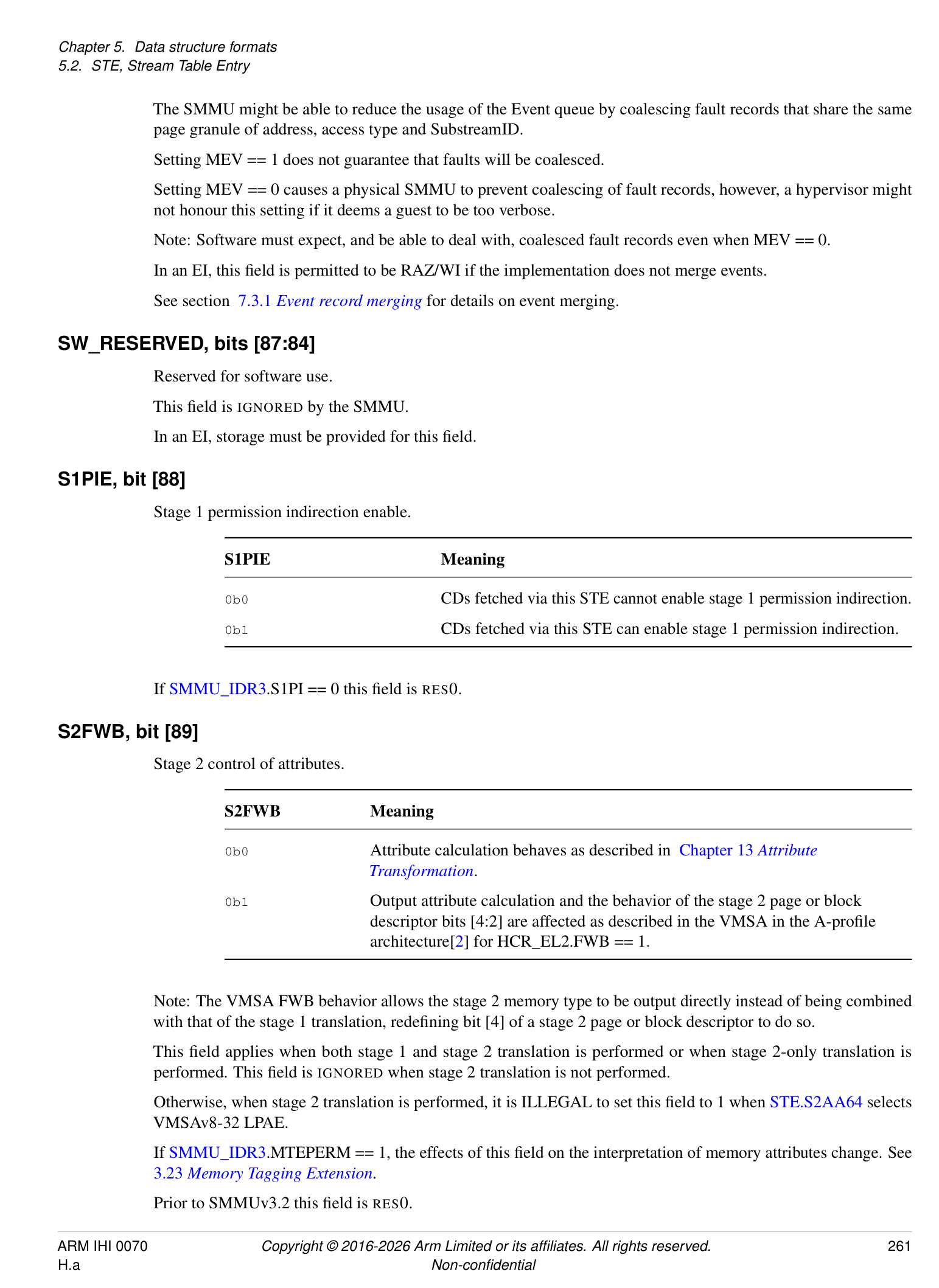
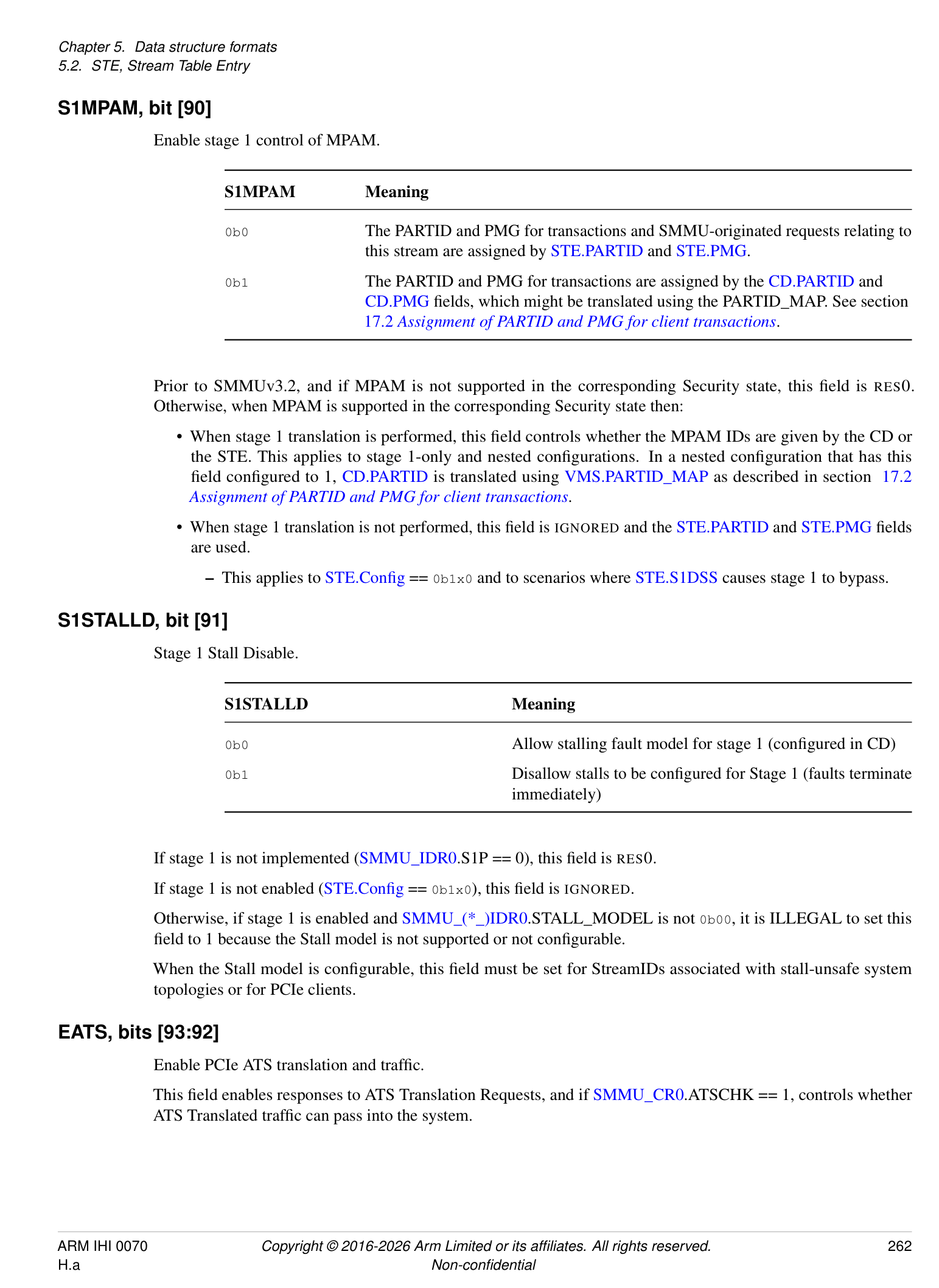
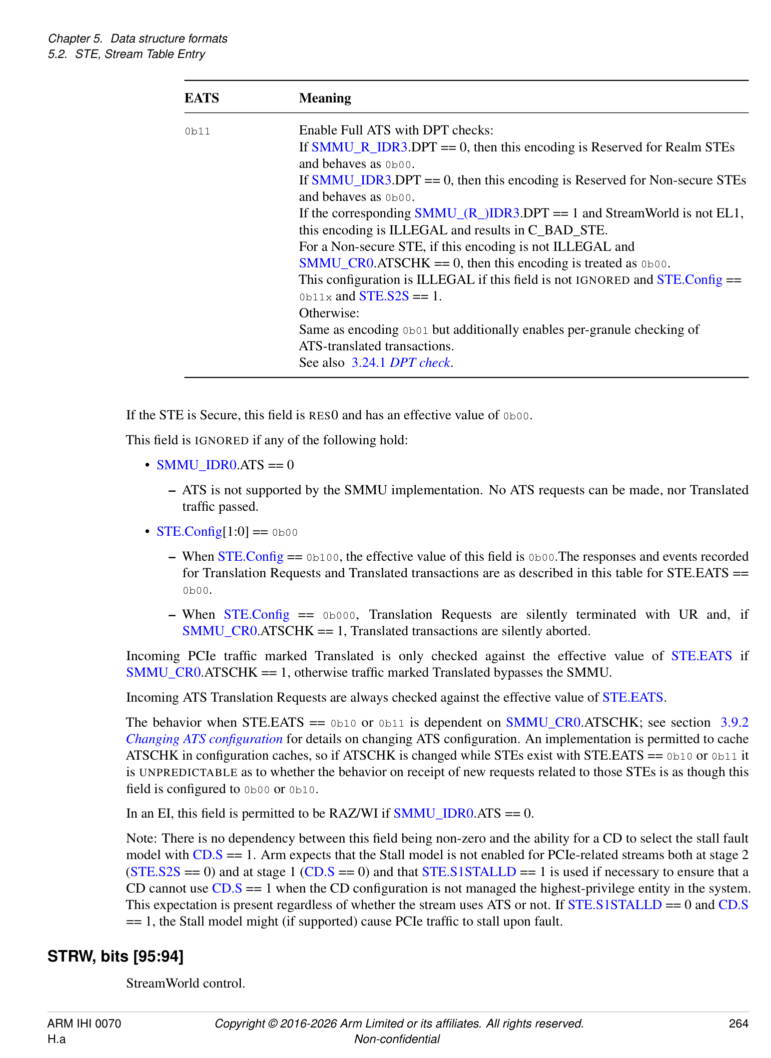
The CD structure contains stage 1 translation table pointers and associated fields (such as ASID and table walk attributes). Translation tables might be interpreted as VMSAv8-32 LPAE, VMSAv8-64 or VMSAv9-128 formats (as controlled by the AA64 field).
Invalid or contradictory CD configurations are marked ILLEGAL. A transaction that attempts to translate through a CD containing ILLEGAL configuration is terminated with an abort and a C_BAD_CD event is recorded in the Event queue appropriate to the Security state of the transaction, as determined by SEC_SID.
Note: In accordance with Armv8-A [2], the interpretation of the translation table descriptor permissions is a function of the translation table format (from CD.AA64) and the Exception level to which the tables correspond (as determined by the STE StreamWorld).
T0SZ, bits [5:0]
Size of VA region covered by TTB0.
This field is equivalent to TCR_ELx.T0SZ in the A-profile architecture[2].
If CD.AA64 selects VMSAv8-32 LPAE:
-
This field is 3 bits ([2:0]) and bits [5:3] are IGNORED.
-
The input region size is calculated the same as in AArch32 TTBCR in the A-profile architecture[2].
-
The valid range of values is 0 to 7 inclusive.
- Note: All 3-bit values are valid, therefore it is not possible to use an out of range value when CD.AA64 selects VMSAv8-32 LPAE.
If CD.AA64 selects VMSAv8-64:
-
This field is 6 bits and the region size is calculated the same as for TCR_ELx.T0SZ in the A-profile architecture[2].
-
If SMMU_IDR3.STT == 0, the maximum valid value is 39.
-
If SMMU_IDR3.STT == 1, the maximum valid value is:
-
48, if the corresponding CD.TGx selects a 4KB or 16KB granule.
-
47, if the corresponding CD.TGx selects a 64KB granule.
-
-
If SMMU_IDR5.VAX indicates support for 52-bit VAs and either of the following also hold, the minimum permitted value is 12:
-
The corresponding CD.TGx selects a 64KB granule size.
-
CD.DS == 1 and the corresponding CD.TGx selects a 4KB or 16KB granule size. Otherwise, the minimum valid value is 16.
-
If CD.AA64 selects VMSAv9-128:
-
The maximum valid value is:
-
48, if CD.TGx selects a 4KB or 16KB granule.
-
47, if CD.TGx selects a 64KB granule.
-
-
The minimum valid value is:
-
8, if SMMU_IDR5.VAX indicates support for 56-bit VAs and StreamWorld is EL3.
-
9, if SMMU_IDR5.VAX indicates support for 56-bit VAs and StreamWorld is EL1 or any-EL2-E2H.
-
12, if SMMU_IDR5.VAX indicates support for 52-bit VAs.
-
16, if SMMU_IDR5.VAX indicates support for 48-bit VAs.
-
Note: VMSAv9-128 is not supported for StreamWorld any-EL2.
In implementations of SMMUv3.1 and later, a CD is treated as ILLEGAL if it contains a TxSZ value outside the range of these maximum and minimum values.
In SMMUv3.0 implementations, a fetch of a CD containing an out of range value is CONSTRAINED UNPREDICTABLE and has one of the following behaviors:
-
The CD becomes ILLEGAL.
-
The CD is not ILLEGAL and the Effective value used by the translation is 39 if the programmed value is greater than 39, or 16 if the programmed value is less than 16.
IGNORED if the Effective value of CD.EPD0 == 1.
TG0, bits [7:6]
TTB0 Translation Granule size, if CD.AA64 selects VMSAv8-64 or VMSAv9-128.
This field is equivalent to TCR_ELx.TG0 in the A-profile architecture[2].
| TG0 | Meaning |
|---|---|
| 0b00 | 4KB |
| 0b01 | 64KB |
| 0b10 | 16KB |
| 0b11 | Reserved |
This field must only select a granule supported by the SMMU, as indicated by SMMU_IDR5. Use of an unsupported size or Reserved value is ILLEGAL, except this field is IGNORED if the effective value of CD.EPD0 == 1.
Note: The different encoding of CD.TG1 to this field is consistent with the Translation System in the A-profile architecture[2].
If CD.AA64 selects VMSAv8-32 LPAE, this field and CD.TG1 are IGNORED.
IR0, bits [9:8]
Inner region Cacheability for TTB0 access.
| IR0 | Meaning |
|---|---|
| 0b00 | Non-cacheable |
| 0b01 | Write-back Cacheable, Read-Allocate, Write-Allocate |
| 0b10 | Write-through Cacheable, Read-Allocate |
| 0b11 | Write-back Cacheable, Read-Allocate, no Write-Allocate |
The only time that translation table entries are written by the SMMU is when HTTU is in use, and because the read effect of the atomic update might cause read allocation of the affected translation table entry into a data cache, it is IMPLEMENTATION DEFINED as to whether 0b01 and 0b11 differ.
Many memory systems might require use of Normal Write-back Cacheable memory for the atomic updates of translation table entries to occur correctly.
If HTTU is enabled and this field is configured to 0b00 or 0b10, then it is IMPLEMENTATION DEFINED which of the following behaviors occurs for hardware updates of Access flag and dirty state:
-
The hardware update occurs correctly as an atomic read-modify-write operation.
-
The hardware update occurs, but the read-modify-write operation is not guaranteed to be atomic.
-
The hardware update is attempted but fails and generates an F_WALK_EABT event.
Arm recommends that software uses 0b01 or 0b11 when HTTU is enabled for this translation table unless the behavior of an implementation is otherwise known.
This field is IGNORED if the effective value of CD.EPD0 == 1.
OR0, bits [11:10]
Outer region Cacheability for TTB0 access.
| OR0 | Meaning |
|---|---|
| 0b00 | Non-cacheable |
| 0b01 | Write-back Cacheable, Read-Allocate, Write-Allocate |
| 0b10 | Write-through Cacheable, Read-Allocate |
| 0b11 | Write-back Cacheable, Read-Allocate, no Write-Allocate |
The behavior of this field is otherwise the same as for CD.IR0.
SH0, bits [13:12]
Shareability for TTB0 access.
| SH0 | Meaning |
|---|---|
| 0b00 | Non-shareable |
| 0b01 | Reserved (behaves as 0b00) |
| 0b10 | Outer Shareable |
| 0b11 | Inner Shareable |
Note: If both CD.IR0 and CD.OR0 are configured to 0b00, selecting normal Non-cacheable access, the Shareability of TTB0 access is taken to be OSH regardless of the value of this field.
IGNORED if the effective value of CD.EPD0 == 1.
EPD0, bit [14]
TTB0 translation table walk disable.
| EPD0 | Meaning |
|---|---|
| 0b0 | Perform translation table walks using TTB0. |
| 0b1 | A TLB miss on an address that is translated using TTB0 causes a Translation fault. |
| No translation table walk is performed. | |
| CD.T0SZ/CD.TG0/CD.IR0/CD.OR0/CD.SH0/CD.TTB0are IGNORED. |
Consistent with translation in the A-profile architecture[2], this field and CD.EPD1 are IGNORED (and their effective value is 0) if this CD is located from an STE with StreamWorld of any-EL2 or EL3. It is only possible for an EL1 (Secure, Non-secure or Realm) or any-EL2-E2H stream to disable translation table walk using this field or CD.EPD1.
ENDI, bit [15]
Translation table endianness.
| ENDI | Meaning |
|---|---|
| 0b0 | Little Endian |
| 0b1 | Big Endian |
If the effective values of both CD.EPD0 and CD.EPD1 are 1, this field is IGNORED. Otherwise:
If SMMU_IDR0.TTENDIAN == 0b10, it is ILLEGAL to set this field to 1.
If SMMU_IDR0.TTENDIAN == 0b11, it is ILLEGAL to set this field to 0.
T1SZ, bits [21:16]
VA region size covered by TTB1.
This field is equivalent to TCR_ELx.T1SZ in the A-profile architecture[2].
This field has the same encoding as CD.T0SZ.
IGNORED if the effective value of CD.EPD1 == 1. If StreamWorld == any-EL2 or EL3, this field is RES0.
TG1, bits [23:22]
TTB1 Translation Granule size.
This field is equivalent to TCR_ELx.TG1 in the A-profile architecture[2].
| TG1 | Meaning |
|---|---|
| 0b00 | Reserved |
| 0b01 | 16KB |
| 0b10 | 4KB |
| 0b11 | 64KB |
This field must only select a granule supported by the SMMU, as indicated by SMMU_IDR5. Use of an unsupported size or Reserved value is ILLEGAL, except this field is IGNORED if the effective value of CD.EPD1 == 1.
Note: The different encoding of this field to CD.TG0 is consistent with the Translation System in the A-profile architecture[2].
If StreamWorld == any-EL2 or EL3 this field is RES0, otherwise if CD.AA64 selects VMSAv8-32 LPAE, CD.TG0 and this field are IGNORED.
IR1, bits [25:24]
Inner region Cacheability for TTB1 access.
Same encoding as CD.IR0.
IGNORED if the effective value of CD.EPD1 == 1. If StreamWorld == any-EL2 or EL3 this field is RES0.
OR1, bits [27:26]
Outer region Cacheability for TTB1 access.
Same encoding as CD.OR0.
IGNORED if the effective value of CD.EPD1 == 1. If StreamWorld == any-EL2 or EL3 this field is RES0.
SH1, bits [29:28]
Shareability for TTB1 access.
Same encoding as CD.SH0.
IGNORED if the effective value of CD.EPD1 == 1. If StreamWorld == any-EL2 or EL3 this field is RES0.
EPD1, bit [30]
TTB1 translation table walk disable.
Same encoding as CD.EPD0.
Affects CD.T1SZ/CD.TG1/CD.IR1/CD.OR1/CD.SH1/CD.TTB1.
V, bit [31]
CD Valid.
| V | Meaning |
|---|---|
| 0b0 | Invalid - use of the CD by an incoming transaction is ILLEGAL |
| 0b1 | Valid |
If this field is 0, the entire rest of the structure is IGNORED. An incoming transaction causing a CD with this field configured to 0 to be located from a valid STE is terminated with an abort and a C_BAD_CD event is recorded.
IPS, bits [34:32]
Intermediate Physical address Size.
This field is equivalent to TCR_ELx.PS in the A-profile architecture[2].
| IPS | Meaning |
|---|---|
| 0b000 | 32 bits |
| 0b001 | 36 bits |
| 0b010 | 40 bits |
| 0b011 | 42 bits |
| 0b100 | 44 bits |
| 0b101 | 48 bits |
| 0b110 | In SMMUv3.0 implementations, this value is Reserved and behaves as |
| 0b101. | |
| In implementations of SMMUv3.1 and later, this value selects 52 bits of IPA. |
| IPS | Meaning |
|---|---|
| 0b111 | In SMMUv3.0 implementations, this value is Reserved and behaves as |
| 0b101. | |
| In implementations of SMMUv3.1 to SMMUv3.3, this value is Reserved | |
| and behaves as 0b110. | |
| In implementations of SMMUv3.4 and later, this value selects 56 bits of IPA. |
Software must not rely on the behavior of Reserved values.
Addresses output from the stage 1 translation table walks through either TTBx table base are range-checked against the effective value of this field, causing a stage 1 Address Size fault if out of range. This means that if the output address of any stage 1 translation has non-zero bits above eff_IPS , where eff_IPS is the effective number of IPA bits, an F_ADDR_SIZE is recorded. See section 3.4 Address sizes .
This check applies to stage 1 next-level table addresses in Table descriptors, as well as stage 1 output addresses in Block and Page descriptors.
If CD.AA64 selects VMSAv8-32 LPAE, IPS is IGNORED and effective stage 1 output address size of 40 bits is always used. This reflects the 40-bit IPA used in VMSAv8-32 LPAE translations. An Address Size fault occurs if the output address bits [47:40] of a VMSAv8-32 LPAE stage 1 translation table descriptor are programmed as non-zero.
If CD.AA64 selects VMSAv8-64 or VMSAv9-128:
-
The effective stage 1 output address size is given by:
-
eff_IPS = MIN(CD.IPS, SMMU_IDR5.OAS);
The effective IPS size is capped to the OAS.
- Setting this field to any value greater than the cap behaves as though this field equals the cap size. Software must not rely on this behavior.
In SMMUv3.0 addresses are limited to 48 bits.
If CD.AA64 selects VMSAv8-64, an address of 52 bits in size can only be represented in a descriptor when:
-
A 64KB granule is in use for that translation table.
-
CD.DS == 1.
An address of 56 bits in size can be represented in a descriptor when CD.AA64 selects VMSAv9-128.
Note: In configurations where the effective IPS is larger than the address output from the descriptor, output bits above the address are treated as zero and no Address Size fault can occur.
AFFD, bit [35]
Access Flag Fault Disable.
When HTTU is not in use because HA == 0 or HTTU is not supported, this flag determines the behavior on access of a stage 1 page whose descriptor has AF == 0:
| AFFD | Meaning |
|---|---|
| 0b0 | An Access fag fault occurs (behavior controlled by ARS bits) |
| 0b1 | An Access fag fault never occurs. The TTD.AF bit is considered to be |
| always 1. |
If HA == 1, this flag is IGNORED.
Note: Because AFFD == 1 causes a TTD.AF bit to be considered to be 1, a resulting TLB entry will contain AF == 1.
WXN, bit [36]
Write Execute Never.
This flag controls overall permission of an instruction read to any writable page located using TTB{0,1}:
| WXN | Meaning |
|---|---|
| 0b0 | Instruction read is allowed as normal |
| 0b1 | Instruction read to writable page raises a Permission fault |
UWXN, bit [37]
Unprivileged Write Execute Never.
This flag controls overall permission of a privileged instruction read to a page marked writable for user privilege that is located through TTB{0,1}:
| UWXN | Meaning |
|---|---|
| 0b0 | Instruction read is allowed as normal |
| 0b1 | Instruction read from user-writable page raises a stage 1 Permission Fault |
In configurations for which all accesses are considered privileged, for example StreamWorld == any-EL2 or StreamWorld == EL3, this field has no effect and is IGNORED.
If CD.AA64 selects VMSAv9-128, this field is RES0.
If CD.AA64 selects VMSAv8-64, this field is IGNORED.
Note: In VMSAv8-64, all EL0-writable regions are treated as being PXN.
TBI0, bit [38]
Top Byte Ignore for TTB0.
TBIx affects generation of a Translation fault for addresses having VA[63:56] dissimilar to a sign-extension of VA[55] in the same way as TBI in the A-profile architecture[2].
Note: Refer to section 3.9.1 ATS Interface for additional considerations for use of TBI with PCIe ATS.
TBI1, bit [39]
Top Byte Ignore for TTB1.
If StreamWorld == any-EL2 or EL3 this field is RES0.
PAN, bit [40]
Privileged Access Never.
When 1, this field disables data read or data write access by privileged transactions to a virtual address where unprivileged access to the virtual address is permitted at stage 1.
Note: See the A-profile architecture[2] for information on PAN.
Note: When HADx is used, the APTable bits do not affect the permission of a translation.
Privileged transactions are those configured through an STE with STE.PRIVCFG == Privileged, or an STE with STE.PRIVCFG == “Use Incoming” and marked as Privileged by the client device.
This field is IGNORED when StreamWorld == any-EL2 or StreamWorld == EL3 and PAN is effectively 0.
AA64, bit [41]
Translation table format for both TTB0 and TTB1.
| AA64 | Meaning | Applies when |
|---|---|---|
| 0b0 | Use VMSAv8-32 LPAE | SMMU_IDR0.TTF[0] == 1 |
| descriptor formats. | ||
| 0b0 | Use VMSAv9-128 descriptor | SMMU_IDR5.D128 == 1 |
| formats. | ||
| 0b1 | Use VMSAv8-64 descriptor | |
| formats. |
Note: This is consistent with the A-profile architecture[2], where use of 128-bit descriptors is supported for EL2&0 translation regimes but not for EL2 translation regimes.
The behavior of this field if SMMU_IDR5.D128 == 1 is equivalent to TCR(2)_ELx.D128 in the A-profile architecture[2], with reversed polarity.
It is ILLEGAL to select VMSAv8-32 LPAE tables when either:
-
VMSAv8-32 LPAE tables are not supported (SMMU_IDR0.TTF[0] == 0)
-
StreamWorld == any-EL2-E2H or S-EL2 or EL3.
It is ILLEGAL to select VMSAv8-64 tables when either:
-
VMSAv8-64 tables are not supported (SMMU_IDR0.TTF[1] == 0)
-
Stage 2 translates (STE.Config == 0b11x) and STE.S2AA64 selects VMSAv8-32.
- Note: Consistent with the VMSA in the A-profile architecture[2], a 64-bit stage 1 is not supported on a 32-bit stage 2.
Note: When VMSAv8-64 is selected, the IPS field selects a variable output address size, the translation granule can be altered, HTTU can be enabled and page permissions are interpreted differently, see the other fields for details.
It is ILLEGAL to select VMSAv9-128 tables if any of the following are true:
-
StreamWorld is EL2. Configuring stage 1 to use VMSAv9-128 tables is permitted if StreamWorld is EL2-E2H in the SMMU, as configured in SMMU_(*_)CR2.E2H and STE.{Config, STRW}.
-
• STE.S1PIE is 0.
This field is permitted to be cached in a TLB.
HD, bit [42]
Hardware Translation Table Update of Dirty flags for CD.TTB0 and CD.TTB1.
See definition of HA.
HA, bit [43]
Hardware Translation Table Update of Access flags for CD.TTB0 and CD.TTB1.
When combined with CD.HD as {HD, HA}:
-
0b00: HTTU disabled.
-
0b01: Update of Access flag enabled.
-
0b10: Reserved. If CD.HD == 1 is not ILLEGAL, behaves as though this field is 0 and CD.HD is 0.
-
0b11: Update of Access flag and dirty state of the page enabled.
These flags are IGNORED if CD.AA64 selects VMSAv8-32 LPAE.
Otherwise:
-
It is ILLEGAL to set HA if SMMU_IDR0.HTTU == 0b00.
-
It is ILLEGAL to set HD if SMMU_IDR0.HTTU == 0b00 or 0b01.
Note: If HTTU is enabled when ORx or IRx indicate Non-cacheable memory, behavior is IMPLEMENTATION DEFINED, see 3.15 Coherency considerations and memory access types . Some systems might only be able to perform atomic updates using normal cacheable memory. Incompatible attributes might cause HTTU not to be performed but system integrity must be maintained as a CD might be under control of a malicious VM.
S, bit [44]
Stage 1 fault behavior.
See section 5.5 Fault configuration (A, R, S bits) for a description of fault configuration.
For accesses with PM = 1, this field is treated as 0 for all purposes other than CD validity checks.
R, bit [45]
Stage 1 fault behavior.
See section 5.5 Fault configuration (A, R, S bits) for a description of fault configuration.
A, bit [46]
Stage 1 fault behavior.
See section 5.5 Fault configuration (A, R, S bits) for a description of fault configuration.
ASET, bit [47]
ASID Set.
Selects type for ASID, between sets shared and non-shared with PE ASIDs. This flag affects broadcast TLB invalidation participation and the scope within which Global TLB entries are matched:
| ASET | Meaning |
|---|---|
| 0b0 | ASID in shared set: This ASID, and address space described byCD.TTB0and |
| CD.TTB1, are shared with that of a process on the PE. All matching broadcast | |
| invalidation messages will invalidate TLB entries created from this context (where | |
| supported and globally enabled), keeping SMMU and PE address spaces | |
| synchronized. | |
| 0b1 | ASID in non-shared set: TLB entries created from this context are not expected to |
| be invalidated by some broadcast invalidations as described in section 3.17_TLB_ | |
| tagging, VMIDs, ASIDs and participation in broadcast TLB maintenance. |
For invalidation by ASID scope such entries require SMMU invalidation commands to be issued. This ASID represents an SMMU-local address space, not shared with PE processes, therefore broadcast invalidation from a coincidentally matching ASID is irrelevant to this address space. Use of ASET == 1 might avoid over-invalidation and improve performance.
Note: All other broadcast TLB invalidations, except for those listed here, are expected to affect matching TLB entries created when ASET == 1. For example, TLBI VMALLE1IS must invalidate all TLB entries matching a given VMID, regardless of ASET.
ASET must be included in any Global cached translations inserted using a CD reached through an STE with StreamWorld == NS-EL1 or Secure or any-EL2-E2H. In these StreamWorlds, ASET is also intended (but not required) to be included in non-Global translations to allow them to opt-out of broadcast invalidation.
Changes to a the ASET of a CD or the ASID, or both, are not automatically reflected in cached translations. Arm recommends that these are subjected to separate TLB maintenance.
ASET is permitted to be included in cached translations inserted using a CD reached through an STE with StreamWorld == any EL2 or EL3.
ASID, bits [63:48]
Address Space Identifier.
See ASET field. Tag for TLB entries inserted due to translations from this CD, differentiating them from translations with the same VA from different address spaces.
ASID must tag all cached translations inserted using this CD through an STE with StreamWorld == NS-EL1 or Secure or any-EL2-E2H.
This field is IGNORED if StreamWorld == any-EL2 or EL3. Otherwise, when an implementation supports only 8-bit ASIDs (SMMU_IDR0.ASID16 == 0), it is ILLEGAL for ASID[15:8] to be non-zero.
If 16-bit ASIDs are supported by an implementation, the full ASID[15:0] value is used regardless of CD.AA64. Arm expects that legacy/AArch32 software using 8-bit ASIDs will write zero-extended 8-bit values in the ASID field in this case.
NSCFG0, bit [64]
Non-secure attribute for the memory associated with the starting-level translation table to which CD.TTB0 points.
| NSCFG0 | Meaning | |||
|---|---|---|---|---|
| 0b0 | Starting-level descriptor ofCD.TTB0 | is fetched using NS == | 0 | access |
| 0b1 | Starting-level descriptor ofCD.TTB0 | is fetched using NS == | 1 | access |
This field is used only when the CD is reached from a Secure STE and is otherwise IGNORED.
Bit [65]
When SMMUIDR5.D128 == 1:
DisCH0, bit [65]
Disable the Contiguous bit for the initial level of walk for CD.TTB0.
This field is equivalent to TCR(2)_ELx.DisCH0 in the A-profile architecture[2].
| DisCH0 | Meaning |
|---|---|
| 0b0 | No effect on the Contiguous bit. |
| 0b1 | The Contiguous bit in Block or Page descriptors at the initial |
| level of walk is treated as 0. |
The interpretation of this field only applies if CD.AA64 selects VMSAv9-128.
If CD.EPD0 is 1, this field is IGNORED.
This field is permitted to be cached in a TLB.
Otherwise:
HAD0, bit [65]
Hierarchical Attribute Disable for the CD.TTB0 region.
| HAD0 | Meaning |
|---|---|
| 0b0 | Hierarchical attributes are enabled. |
| 0b1 | Hierarchical attributes are disabled. |
The presence of this feature can be determined from SMMU_IDR3.HAD; if SMMU_IDR3.HAD == 0, this field and CD.HAD1 are IGNORED. Otherwise:
When this field is 1, the APTable, PXNTable and XNTable/UXNTable fields of table descriptors walked through CD.TTB0 become IGNORED, might be used by software for any purpose and do not affect translation. When StreamWorld == any-EL2 or EL3, this effect includes the APTable[0] and PXNTable bits which are otherwise Reserved by VMSA in these translation regimes.
This field and CD.HAD1 are supported for both VMSAv8-32 LPAE and VMSAv8-64 translation tables.
E0PD0, bit [66]
Disable unprivileged access to addresses translated by CD.TTB0.
When an access is prevented by the E0PD mechanism, the event is reported as a Translation Fault, F_TRANSLATION.
This field is equivalent to TCR_ELx.E0PD0 in the A-profile architecture[2].
Note: Consistent with FEAT_E0PD in the A-profile architecture[2], Arm expects that the fault should take the same time to generate, whether the address is present in the TLB or not, to mitigate attacks that use fault timing.
E0PD only applies to VMSAv8-64 translation regimes with StreamWorld configured as EL1, Secure or any-EL2-E2H.
| E0PD0 | Meaning |
|---|---|
| 0b0 | Unprivileged access to any address translated byCD.TTB0will not |
| generate a fault by this mechanism | |
| 0b1 | Unprivileged access to any address translated byCD.TTB0will |
| generate a Translation fault |
If SMMU_IDR3.E0PD == 0 this field is RES0.
If CD.AA64 selects VMSAv8-32 LPAE or if StreamWorld is EL3 or any-EL2, this field is RES0.
This field is permitted to be cached in a TLB.
HAFT, bit [67]
Enable hardware update of Access flag in Table descriptors.
| HAFT | Meaning |
|---|---|
| 0b0 | Stage 1 HAFT disabled. |
| 0b1 | Stage 1 HAFT enabled. |
If CD.HA is 0 and not IGNORED, it is ILLEGAL to set this field to 1 and this results in C_BAD_CD.
This field is permitted to be cached in a TLB.
If SMMU_IDR0.HTTU != 0b11 this field is RES0.
TTB0, bits [119:68]
In SMMUv3.1 and later, if CD.AA64 selects VMSAv9-128, then bits[119:68] represent the address of the TT0 base, bits[55:4]. Otherwise:
-
In SMMUv3.1 and later:
-
Bits[115:68] represent the address of the TT0 base, bits[51:4].
-
Bits[119:116] are RES0.
-
-
In SMMUv3.0:
-
Bits[111:68] represent the address of the TT0 base, bits[47:4].
-
Bits[119:112] are RES0.
-
Address bits above and below the field range are implied as zero.
Bits [(x-1):0] are treated as if all the bits are zero, where x is defined by the required alignment of the translation table as given by the VMSA in the A-profile architecture[2].
Note: The SMMU effectively aligns the value in this field before use.
If CD.AA64 selects VMSAv8-64, then a 64-byte minimum alignment on starting-level translation table addresses is imposed when the effective IPS value indicates 52-bit output. In this case bits [5:0] are treated as zero.
If CD.AA64 selects VMSAv9-128, then a 32-byte minimum alignment on starting-level translation table addresses is imposed regardless of the effective IPS value. In this case bits [4:0] are treated as zero.
If the effective value of CD.EPD0 == 1, this field is IGNORED. Otherwise, it is ILLEGAL for the address in this field to be outside the range described by the CD’s effective IPS value. In addition, it is ILLEGAL for the address in this field to be outside of a 48-bit range when CD.DS == 0, CD.AA64 selects VMSAv8-64 and CD.TG0 selects a granule smaller than 64KB.
FNG0, bit [120]
When SMMUIDR3.FNG == 1:
Force non-global translations for TTB0.
| FNG0 | Meaning |
|---|---|
| 0b0 | This bit has no effect on the interpretation of the nG bit. |
| 0b1 | Translations by TTB0 are treated as non-global regardless of the value of the |
| nG bit. |
If CD.AA64 selects VMSAv8-32, this field is RES0.
If StreamWorld == any-EL2 or EL3, this field is RES0.
This field is permitted to be cached in a TLB.
Otherwise:
Reserved, RES0.
MTOp, bit [121]
Memory type transformation operator.
| MTOp | Meaning |
|---|---|
| 0b0 | Input memory type to stage 1 is replaced with the memory type |
| specifed by stage 1. | |
| 0b1 | Input memory type to stage 1 is combined with the memory type |
| specifed by stage 1. |
If STE.MTCFG == 1 and this field is configured to combine, then STE.MemAttr is combined with the memory type specified by stage 1.
If SMMU_IDR3.MTCOMB == 0 this field is RES0 and has no effect.
Note: ATOS requests do not supply memory attributes. Therefore, the SMMU constructs and assigns default memory attributes to these requests. See section 13.1.3 Default input attributes .
PnCH, bit [122]
Stage 1 Protected attribute enable.
This field is equivalent to TCR(2)_ELx.PnCH in the A-profile architecture[2].
| PnCH | Meaning |
|---|---|
| 0b0 | Protected attribute disabled. |
| 0b1 | Protected attribute enabled. |
If CD.AA64 selects VMSAv9-128, then this field is RES0. If VMSAv9-128 is selected, the functionality of this field is implicitly enabled, however, the Contiguous bit disable property of this field does not apply. If CD.AA64 selects VMSAv8-32 LPAE, then this field is RES0.
If SMMU_IDR3.THE == 0 this field is RES0.
See also:
-
3.27.1 Protected attribute .
-
3.27.2 AssuredOnly permission checks .
This field is permitted to be cached in a TLB.
EPAN, bit [123]
Control for Enhanced PAN mechanism.
| EPAN | Meaning |
|---|---|
| 0b0 | WhenCD.PAN== 1, a privileged data access to a page with stage 1 |
| unprivileged data access permission generates F_PERMISSION as a result | |
| of the Privileged Access Never mechanism. | |
| 0b1 | WhenCD.PAN== 1, a privileged data access to a page with stage 1 |
| unprivileged data or stage 1 unprivileged instruction access permission | |
| generates F_PERMISSION as a result of the Privileged Access Never | |
| mechanism. Any data access, including speculative accesses, that is | |
| prevented byCD.PAN== 1 will not cause allocation into a cache. |
If any of the following are true this field is RES0:
-
CD.AA64 selects VMSAv8-32 LPAE.
-
StreamWorld is any-EL2 or EL3.
-
Stage 1 permission indirection is enabled. Note: If stage 1 permission indirection is enabled, and CD.PAN is 1, the PAN check behaves as though this field is also 1. See section 3.26.1 Stage 1 permission indirections .
If SMMU_IDR3.EPAN == 0 this field is RES0.
This field is permitted to be cached in a TLB.
HWU059, bit [124]
If SMMU_IDR3.PBHA == 1 and CD.HAD0 == 1, this field controls the interpretation of bit [59] of the stage 1 translation table final-level (page or block) descriptor pointed at by CD.TTB0:
| HWU059 | Meaning |
|---|---|
| 0b0 | Bit [59] is not interpreted by hardware for an IMPLEMENTATION |
| DEFINEDpurpose. | |
| 0b1 | Bit [59] has IMPLEMENTATION DEFINEDhardware use. |
This field is IGNORED when PBHA are not supported (SMMU_IDR3.PBHA == 0) or when CD.HAD0 == 0.
If CD.AA64 selects VMSAv9-128, this field is RES0.
In SMMUv3.0 this field is RES0.
HWU060, bit [125]
Similar to CD.HWU059, but affecting descriptor bit [60].
Bits [127:126]
When SMMUIDR5.D128 == 1:
SKL0, bits [127:126]
Skip Level configuration for initial lookup for stage 1 translations using TTB0.
This field is equivalent to TTBR0_ELx.SKL in the A-profile architecture[2].
| SKL0 | Meaning |
|---|---|
| 0b00 | Skip 0 levels. |
| 0b01 | Skip 1 level. |
| 0b10 | Skip 2 levels. |
| 0b11 | Skip 3 levels. |
The interpretation of this field only applies if CD.AA64 selects VMSAv9-128.
If CD.EPD0 is 1, this field is IGNORED.
This field is permitted to be cached in a TLB.
Otherwise:
HWU0<x>, bits [127:126]
HWU062 and HWU061.
Similar to CD.HWU059, but affecting descriptor bits [62, 61].
NSCFG1, bit [128]
Non-secure attribute for the memory associated with the starting-level translation table to which CD.TTB1 points. See CD.NSCFG0.
If StreamWorld == any-EL2 or EL3 this field is RES0.
Bit [129]
When SMMUIDR5.D128 == 1:
DisCH1, bit [129]
Disable the Contiguous bit for the initial level of walk for CD.TTB1.
This field is equivalent to TCR(2)_ELx.DisCH1 in the A-profile architecture[2].
| DisCH1 | Meaning |
|---|---|
| 0b0 | No effect on the Contiguous bit. |
| 0b1 | The Contiguous bit in Block or Page descriptors at the initial |
| level of walk is treated as 0. |
The interpretation of this field only applies if CD.AA64 selects VMSAv9-128.
If StreamWorld is EL3 or any-EL2, this field is RES0.
If CD.EPD1 is 1, this field is IGNORED.
This field is permitted to be cached in a TLB.
Otherwise:
HAD1, bit [129]
Hierarchical Attribute Disable for the CD.TTB1 region.
| HAD1 | Meaning |
|---|---|
| 0b0 | Hierarchical attributes are enabled |
| 0b1 | Hierarchical attributes are disabled |
If SMMU_IDR3.HAD == 1, this field is RES0 if StreamWorld == any-EL2 or EL3.
E0PD1, bit [130]
Disable unprivileged access to addresses translated by CD.TTB1.
When an access is prevented by the E0PD mechanism, the event is reported as a Translation Fault, F_TRANSLATION.
This field is equivalent to TCR_ELx.E0PD1 in the A-profile architecture[2].
Note: Consistent with FEAT_E0PD in the A-profile architecture[2], Arm expects that the fault should take the same time to generate, whether the address is present in the TLB or not, to mitigate attacks that use fault timing.
E0PD only applies to VMSAv8-64 translation regimes with StreamWorld configured as EL1, Secure or any-EL2-E2H.
| E0PD1 | Meaning |
|---|---|
| 0b0 | Unprivileged access to any address translated byCD.TTB1will not |
| generate a fault by this mechanism | |
| 0b1 | Unprivileged access to any address translated byCD.TTB1will |
| generate a Translation fault |
If SMMU_IDR3.E0PD == 0 this field is RES0.
If CD.AA64 selects VMSAv8-32 LPAE or if StreamWorld is EL3 or any-EL2, this field is RES0.
This field is permitted to be cached in a TLB.
AIE, bit [131]
Enable stage 1 attribute extension.
| AIE | Meaning |
|---|---|
| 0b0 | Stage 1 attribute extension is disabled. |
| 0b1 | Stage 1 attribute extension is enabled. |
If SMMU_IDR3.AIE is 0, this field is RES0.
For more information see CD.{MAIR0, MAIR1}.
This field is permitted to be cached in a TLB.
TTB1, bits [183:132]
In SMMUv3.1 and later, if CD.AA64 selects VMSAv9-128, then bits[183:132] represent the address of the TT1 base, bits[55:4]. Otherwise:
-
In SMMUv3.1 and later:
-
Bits[179:132] represent the address of the TT1 base, bits[51:4].
-
Bits[183:180] are RES0.
-
-
In SMMUv3.0:
-
Bits[175:132] represent the address of the TT1 base, bits[47:4].
-
Bits[183:176] are RES0.
-
Address bits above and below the field range are implied as zero.
See the notes below about when CD.TTB1 might be valid.
Bits [(x-1):0] are treated as if all the bits are zero, where x is defined by the required alignment of the translation table as given by the VMSA in the A-profile architecture[2].
Note: The SMMU effectively aligns the value in this field before use.
If CD.AA64 selects VMSAv8-64, then a 64-byte minimum alignment on starting-level translation table addresses is imposed when the effective IPS value indicates 52-bit output. In this case bits [5:0] are treated as zero.
If CD.AA64 selects VMSAv8-128, then a 32-byte minimum alignment on starting-level translation table addresses is imposed regardless of the effective IPS value. In this case bits [4:0] are treated as zero.
If StreamWorld == any-EL2 or EL3 this field is RES0, otherwise if the effective value of CD.EPD1 == 1, this field is IGNORED. Otherwise, it is ILLEGAL for the address in this field to be outside the range described by the effective IPS value of the CD. In addition, it is ILLEGAL for the address in this field to be outside of a 48-bit range when CD.DS == 0, CD.AA64 selects VMSAv8-64 and CD.TG1 selects a granule smaller than 64KB.
FNG1, bit [184]
When SMMUIDR3.FNG == 1:
Force non-global translations for TTB1.
| FNG1 | Meaning |
|---|---|
| 0b0 | This bit has no effect on the interpretation of the nG bit. |
| 0b1 | Translations by TTB1 are treated as non-global regardless of the value of the |
| nG bit. |
If CD.AA64 selects VMSAv8-32, this field is RES0.
If StreamWorld == any-EL2 or EL3, this field is RES0.
This field is permitted to be cached in a TLB.
Otherwise:
Reserved, RES0.
Bit [185]
Reserved, RES0.
DS, bit [186]
Enable 52-bit input and output address size when using 4KB and 16KB granules.
| DS | Meaning |
|---|---|
| 0b0 | 52-bit address sizes when using 4KB and 16KB granules disabled. |
| 0b1 | 52-bit address sizes when using 4KB and 16KB granules enabled. |
This field affects both the input and output address sizes, as follows:
-
The effect of this field on the interpretation of stage 1 translation table descriptors is the same as for the TCR_ELx.DS bit as specified in FEAT_LPA2 in the A-profile architecture[2].
-
The effect of this field on the determination of whether the CD.TxSZ fields are configured to out-of-range values is the same as for the TCR_ELx.DS bit specified in FEAT_LPA2 in the A-profile architecture[2].
If this field is 1 and CD.TGx selects 4KB or 16KB, then the Shareability attribute for a Cacheable location translated by tables pointed to by CD.TTBx is taken from CD.SHx.
If any of the following are true this field is RES0:
-
SMMU_IDR5.DS == 0.
-
CD.AA64 selects VMSAv9-128.
-
CD.AA64 selects VMSAv8-32 LPAE.
-
StreamWorld == EL1 or EL2-E2H, and both CD.TG0 and CD.TG1 select 64KB.
-
StreamWorld == EL2 or EL3, and CD.TG0 selects 64KB.
PIE, bit [187]
Stage 1 permission indirection enable.
This field is equivalent to TCR(2)_ELx.PIE in the A-profile architecture[2].
| PIE | Meaning |
|---|---|
| 0b0 | Use permissions directly from stage 1 translation table descriptors. |
| 0b1 | Use stage 1 Indirect Permission Scheme. |
If any of the following conditions are true this field is RES0:
-
SMMU_IDR3.S1PI is 0.
-
STE.S1PIE is 0.
-
CD.AA64 selects VMSAv9-128. Stage 1 permission indirection is implicitly enabled.
-
CD.AA64 selects VMSAv8-32. Stage 1 permission indirection is not supported.
This field is permitted to be cached in a TLB.
HWU159, bit [188]
If SMMU_IDR3.PBHA == 1 and CD.HAD1 == 1, this field controls the interpretation of bit [59] of the Stage 1 translation table final-level (page or block) descriptor pointed at by CD.TTB1:
| HWU159 | Meaning |
|---|---|
| 0b0 | Bit [59] is not interpreted by hardware for an IMPLEMENTATION |
| DEFINEDpurpose. | |
| 0b1 | Bit [59] has IMPLEMENTATION DEFINEDhardware usage. |
This field is IGNORED when PBHA are not supported (SMMU_IDR3.PBHA == 0) or when CD.HAD1 == 0.
In SMMUv3.0 this field is RES0.
HWU160, bit [189]
Similar to CD.HWU159, but affecting descriptor bit [60].
Bits [191:190]
When SMMU_IDR5.D128 == 1:
SKL1, bits [191:190]
Skip Level configuration for initial lookup for stage 1 translations using TTB1.
This field is equivalent to TTBR1_ELx.SKL in the A-profile architecture[2].
| SKL1 | Meaning |
|---|---|
| 0b00 | Skip 0 levels. |
| 0b01 | Skip 1 level. |
| 0b10 | Skip 2 levels. |
| 0b11 | Skip 3 levels. |
The interpretation of this field only applies if CD.AA64 selects VMSAv9-128.
Otherwise behaves the same as CD.SKL0, but for translations using TTB1.
If StreamWorld is EL3 or any-EL2, this field is RES0. If CD.EPD1 is 1, this field is IGNORED.
This field is permitted to be cached in a TLB.
Otherwise:
HWU1<x>, bits [191:190]
HWU162 and HWU161. Similar to HWU159, but affecting descriptor bits [62, 61].
MAIR0, bits [223:192]
Memory Attribute Indirection Register 0, bits[31:0].
MAIR1, bits [255:224]
Memory Attribute Indirection Register 1, bits[31:0].
Equivalent to the A-profile architecture[2] Memory Attribute Indirection Registers, the MAIR0 and MAIR1 fields are indexed by AttrIndx in descriptors fetched from TTB0 & TTB1 and contain attributes encoded in the same way as in Arm VMSAv8-64 MAIR registers with the following exceptions:
All encodings defined as UNPREDICTABLE in VMSAv8-64 are Reserved in this architecture, and behave as follows:
| Attr<n>[3:0] | If Attr<n>[7:4] == 0b0000 | If Attr<n>[7:4] != 0b0000 |
|---|---|---|
| 0b0000 | Same as VMSAv8-64 | Reserved, behaves as Normal-iWT Transient |
| with RW = 0b11 | ||
| 0b00RWwhere RW != 0b00 | Reserved, behaves as Device-nGnRnE | Same as VMSAv8-64 |
| 0b01RWwhere RW != 0b00 | Reserved, behaves as Device-nGnRE | Same as VMSAv8-64 |
| 0b10RWwhere RW != 0b00 | Reserved, behaves as Device-nGRE | Same as VMSAv8-64 |
| 0b11RWwhere RW != 0b00 | Reserved, behaves as Device-GRE | Same as VMSAv8-64 |
Note: The encoding 0b11110000, “Tagged Normal Memory” in the A-profile architecture[2] is not supported in SMMUv3.
MAIR, as referenced in the table below, is the concatenation of {CD.MAIR1, CD.MAIR0} as a 64-bit value. If SMMU_IDR3.AIE is 0 or CD.AIE is 0, then MAIR is indexed by AttrIndx[2:0] from stage 1 Block or Page descriptors. If SMMU_IDR3.AIE is 1 and CD.AIE is 1 then MAIR is indexed by AttrIndx[3:0] as follows:
| AttrIndx[3:0] | MAIR output |
|---|---|
| 7 >= x >= 0 | Bits [(8x)+7 : 8x] |
| x>7 | Bits [63:56] |
Consistent with the A-profile architecture[2], AttrIndx[3] is derived as follows:
-
If CD.AA64 selects VMSAv8-64, then AttrIndx[3] is bit [59] of Block and Page descriptors.
-
If CD.AA64 selects VMSAv9-128, then AttrIndx[3] is bit [5] of Block and Page descriptors.
AMAIR0, bits [287:256]
Auxiliary Memory Attribute Indirection Register 0, bits[31:0].
AMAIR1, bits [319:288]
Auxiliary Memory Attribute Indirection Register 1, bits[31:0].
Equivalent to PE Auxiliary Memory Attribute Indirection Registers. The content of the AMAIR{1,0} fields is IMPLEMENTATION DEFINED and might enable extended functionality.
If software has no IMPLEMENTATION SPECIFIC knowledge it must set the AMAIR{1,0} fields to zero. An implementation must remain compatible with generic driver software by maintaining correct behavior when the AMAIR is set to zero.
If SMMU_IDR3.AIE is 0 or CD.AIE is 0, then in a typical implementation, the AMAIR{1,0} fields are split into eight one-byte fields indexed by the AttrIndx[2:0] field from stage 1 Block or Page descriptors but this is not required. If SMMU_IDR3.AIE is 1 and CD.AIE is 1 then AMAIR is indexed by AttrIndx[3:0] from stage 1
Block or Page descriptors as follows: Note: AMAIR, as referenced in the table below, is the concatenation of {CD.AMAIR1, CD.AMAIR0} as a 64-bit value.
| AttrIndx[3:0] | AMAIR output |
|---|---|
| 7 >= x >= 0 | Bits [(8x)+7 : 8x] |
| x>7 | Bits [63:56] |
Consistent with the A-profile architecture[2], AttrIndx[3] is derived as follows:
-
If CD.AA64 selects VMSAv8-64, then AttrIndx[3] is bit [59] of Block and Page descriptors.
-
If CD.AA64 selects VMSAv9-128, then AttrIndx[3] is bit [5] of Block and Page descriptors.
IMPLEMENTATION DEFINED, bits [351:320]
IMPLEMENTATION DEFINED, for example QoS, allocation, or transient hints for translation table access.
PARTID, bits [367:352]
MPAM Partition ID.
If MPAM is not supported in the corresponding Security state, or if STE.S1MPAM == 0, this field is RES0. Otherwise:
When STE.Config == 0b111 and STE.S1MPAM == 1, PARTID[4:0] is the 5-bit virtual PARTID used for client transactions. Bits [15:5] are RES0. The virtual ID is translated to a physical ID using the VMS.PARTID_MAP structure.
When STE.Config == 0b101 and STE.S1MPAM == 1, this field is the physical PARTID used for client transactions. In this configuration, this field is interpreted as having an UNKNOWN value if it is configured with a value greater than the corresponding SMMU_(*_)MPAMIDR.PARTID_MAX.
The corresponding SMMU_(*_)MPAMIDR.PARTID_MAX is chosen as follows:
-
For a Non-secure Stream, then SMMU_MPAMIDR.PMG_MAX.
-
For a Secure Stream, if SMMU_S_MPAMIDR.HAS_MPAM_NS == 0 or STE.MPAM_NS == 0, then SMMU_S_MPAMIDR.PMG_MAX.
-
For a Secure Stream, if SMMU_S_MPAMIDR.HAS_MPAM_NS == 1 and STE.MPAM_NS == 1, then SMMU_MPAMIDR.PMG_MAX.
See Chapter 17 Memory System Resource Partitioning and Monitoring for more information on use of this field.
PMG, bits [375:368]
MPAM Performance Monitor Group.
If MPAM is not supported in the corresponding Security state or if STE.S1MPAM == 0, this field is RES0.
This field is interpreted as having an UNKNOWN value if it is configured with a value greater than the corresponding SMMU_(*_)MPAMIDR.PMG_MAX.
The corresponding SMMU_(*_)MPAMIDR.PMG_MAX is chosen as follows:
-
For a Non-secure Stream, then SMMU_MPAMIDR.PMG_MAX.
-
For a Secure Stream, if SMMU_S_MPAMIDR.HAS_MPAM_NS == 0 or STE.MPAM_NS == 0, then SMMU_S_MPAMIDR.PMG_MAX.
-
For a Secure Stream, if SMMU_S_MPAMIDR.HAS_MPAM_NS == 1 and STE.MPAM_NS == 1, then SMMU_MPAMIDR.PMG_MAX.
See Chapter 17 Memory System Resource Partitioning and Monitoring for more information on use of this field.
Bits [383:376]
Reserved, RES0.
PIIU<p> , bits [3p+386:3p+384], for p = 15 to 0
The set of 16 stage 1 Unprivileged base permission interpretations.
This field is indexed by the PIIndex value derived from a stage 1 Block or Page descriptor, as PIIU[(PIIndex3)+2 : PIIndex3], to give a permission interpretation.
| PIIU<p> | Meaning |
|---|---|
| 0b000 | No Access. |
| 0b001 | Read-only. |
| 0b010 | Execute-only. |
| 0b011 | Read-execute. |
| 0b101 | Read-write. |
| 0b111 | Read-write-execute. |
All other values are reserved, and treated as C_BAD_CD.
If StreamWorld is EL3 or any-EL2, this field is RES0.
Note: The encoding of this field is different from the encoding of the Perm field in the PIRE0_ELx registers in the A-profile architecture[2].
If stage 1 permission indirection is disabled, this field is RES0.
This field is permitted to be cached in a TLB.
Bits [447:432]
Reserved, RES0.
PIIP<p> , bits [3p+450:3p+448], for p = 15 to 0
The set of 16 stage 1 Privileged base permission interpretations.
This field is indexed by the PIIndex value derived from a stage 1 Block or Page descriptor, as PIIP[(PIIndex3)+2 : PIIndex3], to give a permission interpretation.
| PIIP<p> | Meaning |
|---|---|
| 0b000 | No Access. |
| 0b001 | Read-only. |
| 0b010 | Execute-only. |
| 0b011 | Read-execute. |
| 0b101 | Read-write. |
| 0b111 | Read-write-execute. |
All other values are reserved, and treated as C_BAD_CD.
If PIIP[x] grants Privileged execute permission, and CD.PIIU[x] is not RES0 and grants Unprivileged write permission, this is ILLEGAL and results in C_BAD_CD.
Note: The encoding of this field is different from the encoding of the Perm field in the PIR_ELx registers in the A-profile architecture[2].
If stage 1 permission indirection is disabled, this field is RES0.
This field is permitted to be cached in a TLB.
Bits [511:496]
Reserved, RES0.
5.4.1 CD notes
Note: Consistent with Armv8.1 [2] PE translation, translation table descriptor bits APTable, PXNTable and UXNTable control hierarchical permission attributes for lower levels of translation table walks. Not all systems use this feature, so the CD Hierarchical Attribute Disable flags allow translation table walks using TTB0 and TTB1 to be performed ignoring these bits. Software is then free to use the APTable, PXNTable and UXNTable fields for other purposes.
When a CD is used from a stream configured with StreamWorld == any-EL2 or EL3 (but not any-EL2-E2H):
-
Only one translation table is supported (TTB0) and TTB1 is unreachable.
-
ASID is IGNORED.
When TTB1 is unreachable:
- The following fields become RES0:
TTB1, TBI[1], TG1, SH1, OR1, IR1, T1SZ, HAD1, NSCFG1.
- T0SZ must cover the required VA input space
A CD must only be configured to be located through a set of multiple STEs when all STEs in the set configure an identical Exception level (given by the STE StreamWorld).
Note: For example, one STE configuring a stream as NS-EL2 and another STE configuring a stream as NS-EL1 must not both share the same CD as, in this configuration, TTB1 is both enabled and unused depending on the StreamID that locates the CD. Similarly, a CD with AA64 == 0 is ILLEGAL if reached from an STE with StreamWorld == any-EL2-E2H but not if reached from an STE with StreamWorld == NS-EL1 or Secure.
The legality of a CD is, in part, affected by following properties of the STE used to locate the CD:
-
StreamWorld.
-
S1STALLD.
-
AA64 and Config[1] (to detect VMSAv8-32 LPAE stage 2 translation).
When a CD is reached from an STE whose state causes the CD to be considered ILLEGAL, C_BAD_CD is raised and the transaction causing the configuration lookup is terminated with an abort.
When using the Direct Permission Scheme at stage 1, the interpretation of the lower bit of the translation table descriptor AP[2:1] field changes depending on the translation regime under which the table is walked, Translation tables located from STEs with StreamWorld == any-EL2 or EL3 are under EL2 or EL3 AArch64 state ownership and, consistent with Armv8-A PEs, the AP[1] bit (of AP[2:1]) is ignored and treated as 1, see section 13.4.1 Stage 1 page permissions .
Depending on the presentation of an address to the SMMU, TTB1 might never be selected in some implementations, see section 3.4.1 Input address size and Virtual Address size for details.
In Armv8-A, an inconsistency between TTBRx and IPS is reported as an Address Size fault. A CD TTBx address outside the range of IPS makes the CD ILLEGAL, recording a C_BAD_CD error.
A CD or L1CD that is successfully fetched might be cached in any state, therefore any modification, commissioning or decommissioning of a CD must be followed by a CMD_CFGI_CD command to make the modification visible to the SMMU. A failed fetch (F_CD_FETCH, or a stage 2 fault where CLASS == CD) does not cause a CD or L1CD to be cached.
The translation table walks performed from TTB0 or TTB1 are always performed in IPA space if stage 2 translations are enabled (STE.Config == 0b11x). If stage 2 translations are not enabled (or if the SMMU does not implement stage 2), translation table walks are always performed in PA space. CDs are fetched from IPA space if stage 2 translations are enabled, otherwise they are fetched from PA space.
Note: This enables a hypervisor to point directly to guest-managed CD structures and translation tables.
The following CD fields are permitted to be cached as part of a translation or TLB entry, and alteration requires invalidation of any TLB entry that might have cached these fields, in addition to CD structure cache invalidation:
-
HAD{0,1}.
-
AFFD.
-
ASID+ASET (affect tagging of TLB entries, so a change may not require old entries to be invalidated).
-
• MAIR.
-
AMAIR.
-
EPD{0,1}.
-
TTB{0,1}.
-
T{0,1}SZ.
-
OR{0,1}.
-
IR{0,1}.
-
SH{0,1}.
-
ENDI.
-
TG{0,1}.
-
HA, HD.
-
WXN, UWXN.
-
AA64.
-
TBI.
-
IPS.
-
NSCFG{0,1}.
-
PAN.
-
EPAN.
-
PnCH.
-
PIE.
-
PIIP.
-
PIIU.
-
DisCH0.
-
DisCH1.
-
SKL0.
-
SKL1.
-
AIE.
-
HAFT.
-
FNG{0,1}.
Alteration of the remaining fields of the CD does not require an explicit invalidation of any structure other than the CD itself:
- A,R,S
The PARTID and PMG fields are not permitted to be cached in a TLB entry and these fields are permitted to differ between CDs having the same ASID value within the same VMID.
Note: Changes to IMPLEMENTATION DEFINED fields might have IMPLEMENTATION DEFINED invalidation requirements.
When cached in an SMMU, a CD is uniquely identified by the tuple {StreamID, SubstreamID} including the qualification of StreamID by SEC_SID. This means that:
-
Multiple CDs are distinguished by StreamID, so CDs located from the same SubstreamID index but through different StreamIDs are considered separate and can contain different configuration:
- Note: Different devices (StreamIDs) might therefore use the same SubstreamID value to associate transactions with different process address spaces in an OS. The SubstreamID namespace is local to the StreamID.
-
A common CD (or CD table) shared by different STEs is permitted to be cached as multiple entries that are specific to each possible {StreamID, SubstreamID} combination.
-
A change to such a CD requires invalidation of the CD cache. When CMD_CFGI_CD(_ALL) is used, it must be issued multiple times for every {StreamID, SubstreamID} combination that the CD is reachable from.
-
Note: The SMMU might prefetch a reachable structure, so even if a CD was not accessed by a transaction with a particular StreamID, it might have been prefetched through the STE of that stream, so must still be invalidated using that StreamID.
-
It might arise that multiple CDs represent the same address space (therefore TLB entries), as identified by a combination of Security state, StreamWorld or translation regime, VMID tag (if relevant) and ASID tag (if relevant). This can happen in any of the following (non-exhaustive list of) cases:
-
Several STEs with StreamWorld == Secure each point to their own CD that contains a common ASID value
- Secure translation regime differentiates address spaces by ASID (but not VMID).
-
Several STEs with StreamWorld == NS-EL1 contain a common VMID. Each STE points to its own CD that contains a common ASID value:
- NS-EL1 differentiates address spaces by ASID and VMID.
-
An STE with StreamWorld == any-EL2 points to a table of more than one CD.
- EL2 has no ASIDs, therefore multiple CDs represent the same (single) set of translations.
-
An STE with StreamWorld == any-EL2-E2H points to a CD table where some entries use the same ASID value:
- EL2-E2H differentiates address spaces by ASID only.
If multiple CDs exist in the same translation regime representing the same address space, any of these CDs can insert TLB entries matching lookup in that address space. All such CDs are considered interchangeable by the SMMU and must contain identical configuration for fields that are permitted to be cacheable as part of a TLB entry.
Note: The EL2 and EL3 translation regimes do not differentiate address spaces by ASID, therefore all CDs referenced from STEs having StreamWorld any-EL2 or EL3 must be identical for fields permitted to be cacheable in a TLB. This includes tables of multiple CDs referenced from one STE, or CDs referenced one to one from an STE. It is not expected that SubstreamIDs (therefore a CD table with multiple entries) will be used with STEs configured for any-EL2 or EL3 StreamWorlds.
If a software error causes two CDs representing the same address space to differ, the result of a TLB lookup for that address space is UNPREDICTABLE. The SMMU must not allow such an error to provide device access to memory locations outside of the Security state of the stream, or that would not otherwise have been accessible given a stage 2 configuration, if present.
Note: Fields permitted to be cached as part of a TLB entry modify the properties of the TLB entry. A difference in CD configuration can cause TLB entries to be cached with different properties in the same address space. It would be UNPREDICTABLE as to which CD inserted a given TLB entry, therefore the properties returned by a general TLB lookup become UNPREDICTABLE.
5.4.1.1 EPDx behavior
The CD EPD0 and EPD1 fields disable translation configuration related to TTB0 and TTB1, respectively. Validity checks are not performed on fields that are disabled or IGNORED by CD.EPDx.
This table shows interaction of CD.TxSZ with EPDx and incoming addresses that select TTB0 or TTB1 translation configuration:
| Virtual Address | |||||
|---|---|---|---|---|---|
| (VMSAv8-64 example | |||||
| shown) | Effective EPD0 | Effective EPD1 | T0SZ | T1SZ | Result |
| 0xFFFFXXXXXXXXXXXX | 0 | 0 | Valid | Valid | Translates through |
| TTB1 | |||||
| 0x0000XXXXXXXXXXXX | 0 | 0 | Valid | Valid | Translates through |
| TTB0 | |||||
| 0xFFFFXXXXXXXXXXXX | 0 | 0 | X | Invalid(1) | C_BAD_CD |
| 0x0000XXXXXXXXXXXX | 0 | 0 | X | Invalid(1) | C_BAD_CD |
| 0xFFFFXXXXXXXXXXXX | 0 | 0 | Invalid(1) | X | C_BAD_CD |
| 0x0000XXXXXXXXXXXX | 0 | 0 | Invalid(1) | X | C_BAD_CD |
| 0xFFFFXXXXXXXXXXXX | 0 | 1 | Valid | X | TLB miss causes |
| F_TRANSLATION | |||||
| (translation through | |||||
| TTB1 is disabled) | |||||
| 0x0000XXXXXXXXXXXX | 0 | 1 | Valid | X | Translates through |
| TTB0 | |||||
| 0xFFFFXXXXXXXXXXXX | 0 | 1 | Invalid(1) | X | C_BAD_CD |
| 0x0000XXXXXXXXXXXX | 0 | 1 | Invalid(1) | X | C_BAD_CD |
| 0xFFFFXXXXXXXXXXXX | 1 | 0 | X | Valid | Translates through |
| TTB1 | |||||
| 0x0000XXXXXXXXXXXX | 1 | 0 | X | Valid | TLB miss causes |
| F_TRANSLATION | |||||
| (translation through | |||||
| TTB1 is disabled) | |||||
| 0xFFFFXXXXXXXXXXXX | 1 | 0 | X | Invalid(1) | C_BAD_CD |
| 0x0000XXXXXXXXXXXX | 1 | 0 | X | Invalid(1) | C_BAD_CD |
-
The high-order bits or bits of the VA determine whether TTB0 or TTB1 is selected, according to the A-profile architecture[2].
-
In the cases marked[(1)] , TxSZ is shown as being an invalid value and the SMMU treating this as making the CD ILLEGAL, for the purposes of illustration. See CD.T0SZ, this is one of the CONSTRAINED UNPREDICTABLE behaviors for an out-of-range TxSZ.
-
EPDx == 1 causes TxSZ to be IGNORED and an invalid TxSZ value (or an invalid TTBx or TGx value) does not lead to C_BAD_CD.
-
When EPDx == 1, a translation table walk through TTBx causes F_TRANSLATION.
- Note: The A-profile architecture[2] allows a TLB hit to occur for an input address associated with an EPD bit set to 1, but the translation table walk is disabled upon miss.
5.4.2 Validity of CD
The following function indicates whether a CD is considered valid or ILLEGAL, for the purposes of determining a configuration error (C_BAD_CD). Subsequent checks must be performed as part of the translation process and further faults might arise, but these are unrelated to the validity of configuration structures.
// CdIllegal() // =========== // Returns TRUE if CD is considered ILLEGAL // Returns FALSE otherwise boolean CdIllegal(STE_t STE, CD_t CD, bits (2) SEC_SID) // Intermediate values SecurityState sec_sid = DecodeSecSid(SEC_SID); STE_StreamWorld ste_streamworld = SteStreamWorld(STE.Config, STE.STRW, SEC_SID); boolean n_transl_cfg0 = EffectiveCDEPD0(CD.EPD0, ste_streamworld); boolean n_transl_cfg1 = EffectiveCDEPD1(CD.EPD1, ste_streamworld); TGx tg0 = TG0(CD.TG0); TGx tg1 = TG1(CD.TG1); integer ipa_range = CalcPARange(CD.IPS, CD.AA64); boolean using_vmsa32 = SMMU_IDR5.D128 == ‘0’ && CD.AA64 == ‘0’; boolean using_vmsa64 = CD.AA64 == ‘1’; boolean using_vmsa128 = SMMU_IDR5.D128 == ‘1’ && CD.AA64 == ‘0’; bits (2) stall_model; case sec_sid of when SS_NonSecure stall_model = EffectiveSMMU_IDR0_STALL_MODEL(); when SS_Secure stall_model = SMMU_S_IDR0.STALL_MODEL; when SS_Realm stall_model = SMMU_R_IDR0.STALL_MODEL; boolean constr_unpred_TxSZ_or_illegal; if SMMU_AIDR.ArchMajorRev == ‘0000’ && SMMU_AIDR.ArchMinorRev == ‘0000’ then constr_unpred_TxSZ_or_illegal = ConstrainUnpredictableBool(Unpredictable_CD_TxSZ); else // In SMMUv3.1 and later, these cases are always ILLEGAL constr_unpred_TxSZ_or_illegal = TRUE; if CD.V == ‘0’ then // CD is ILLEGAL if not valid return TRUE; if STE.S1STALLD == ‘1’ && CD.S == ‘1’ then // Stalls disabled for the stream but enabled for the CD return TRUE; if SMMU_IDR0.TERM_MODEL == ‘1’ && CD.A == ‘0’ then // Terminating a transaction with RAZ/WI behavior is not supported, // CD.A must be 1. return TRUE; if stall_model == ‘01’ && CD.S == ‘1’ then // Stall is not supported, but CD.S ==1 return TRUE; if stall_model == ‘10’ && CD.S == ‘0’ then // Stall is forced, but CD.S == 0 return TRUE; // Check CD.ENDI if (!n_transl_cfg0 || !n_transl_cfg1) && // CD.ENDI is not IGNORED ((SMMU_IDR0.TTENDIAN == ‘10’ && CD.ENDI == ‘1’) || (SMMU_IDR0.TTENDIAN == ‘11’ && CD.ENDI == ‘0’)) then // Endianess of CD doesn’t match system supported endianess return TRUE;
// Check CD.AA64 // AArch32 tables not supported by system or the above StreamWorlds if using_vmsa32 && ((SMMU_IDR0.TTF == ‘x0’) || ste_streamworld IN {STE_StreamWorld_EL3, STE_StreamWorld_any_EL2_E2H}) then return TRUE; // VMSAv8-32 LPAE tables are not supported for S-EL2 StreamWorld if sec_sid == SS_Secure && ste_streamworld == STE_StreamWorld_any_EL2 && using_vmsa32 then assert SMMU_S_IDR1.SEL2 == ‘1’; return TRUE; // AArch64 tables not supported by system or the STE if using_vmsa64 && ((SMMU_IDR0.TTF == ‘0x’) || (STE.Config == ‘11x’ && STE.S2AA64 == ‘0’ && SMMU_IDR5.D128 == ‘0’)) then return TRUE; // Check CD.HA, CD.HD, CD.HAFT if !using_vmsa32 && // The following conditions are ILLEGAL when VMSAv8-64 or // when VMSAv9-128 are used. // No flag updates supported, but CD wants to update flag (((CD.HA == ‘1’ || CD.HD == ‘1’) && (SMMU_IDR0.HTTU == ‘00’)) || // Only access flag update suppported, but CD updates dirty flag (CD.HD == ‘1’ && SMMU_IDR0.HTTU == ‘01’) || // Hardware update of AF in Table descriptors is supported and enabled, // but update of AF in leaf descriptors is not enabled (SMMU_IDR0.HTTU == ‘11’ && CD.HAFT == ‘1’ && CD.HA == ‘0’)) then return TRUE; // Check CD.ASID. // While in one of the following SteamWorlds, // and the system only supports 8-bit ASIDs, if the CD.ASID field // is non-zero for the 8 MSBs, the CD is ILLEGAL if ste_streamworld IN { STE_StreamWorld_NS_EL1, STE_StreamWorld_Secure, STE_StreamWorld_Realm_EL1, STE_StreamWorld_any_EL2_E2H } && SMMU_IDR0.ASID16 == ‘0’ && CD.ASID<15:8> != ‘00000000’ then return TRUE; // Check CD.TxSZ if (!using_vmsa32 && constr_unpred_TxSZ_or_illegal) && ((!n_transl_cfg0 && CDTxSZInvalid(ste_streamworld, using_vmsa128, CD.DS, CD.T0SZ, tg0)) || (!n_transl_cfg1 && CDTxSZInvalid(ste_streamworld, using_vmsa128, CD.DS, CD.T1SZ, tg1))) then return TRUE; // Check CD.TTBx if !n_transl_cfg0 && ((!using_vmsa32 && !GranuleSupported(tg0)) || CDTTBxOutOfRange(CD.TTB0, CDTTBxValidRange(using_vmsa128, CD.DS, tg0, ipa_range))) then return TRUE; if !n_transl_cfg1 && ((!using_vmsa32 && !GranuleSupported(tg1)) || CDTTBxOutOfRange(CD.TTB1, CDTTBxValidRange(using_vmsa128, CD.DS, tg1, ipa_range))) then return TRUE; // Check VMSAv9-128 if using_vmsa128 then if STE.S1PIE == ‘0’ then // CD uses VMSAv9-128, but STE disables use of permission indirection return TRUE; if ste_streamworld == STE_StreamWorld_any_EL2 then // CD uses VMSAv9-128, but STE selects Stream World EL2 return TRUE;
if ((!n_transl_cfg0 && CDSLInvalidD128(CD.SKL0, CD.T0SZ, tg0)) || (!n_transl_cfg1 && CDSLInvalidD128(CD.SKL1, CD.T1SZ, tg1))) then // CD configured the start level of translation to an invalid value return TRUE; // Check CD.{PIIP,PIIU} (permission indirection) if ((using_vmsa64 && SMMU_IDR3.S1PI == ‘1’ && STE.S1PIE == ‘1’ && CD.PIE == ‘1’) || using_vmsa128) then for i = 0 to 15 if CD.PIIP<(i3)+:3> IN { ‘100’,‘110’ } then // Stage 1 permission indirection is enabled, // but PIIP contains a Reserved encoding return TRUE; // If the stream world supports unprivileged transactions, check PIIU if ste_streamworld IN { STE_StreamWorld_any_EL2_E2H, STE_StreamWorld_NS_EL1, STE_StreamWorld_Realm_EL1, STE_StreamWorld_Secure } then if CD.PIIU<(i3)+:3> IN { ‘100’,‘110’ } then // Stage 1 permission indirection is enabled, // but PIIU contains a Reserved encoding return TRUE; if CD.PIIP<(i3)+:3> == ‘x1x’ && CD.PIIU<(i3)+:3> == ‘1xx’ then // Permitting execution by privileged transactions while also permitting // writes by unprivileged transactions is ILLEGAL return TRUE; // CD is not ILLEGAL return FALSE; // CDTxSZInvalid() // =============== // Returns TRUE if TxSZ is outside the valid range // when stage 1 is using VMSAv8-64 or VMSAv9-128 // Returns FALSE otherwise boolean CDTxSZInvalid(STE_StreamWorld ste_streamworld, boolean using_vmsa128, bit DS, bits (6) TxSZ, TGx TG) integer txsz_min, txsz_max; integer txsz = UInt(TxSZ); // Find txsz_max if SMMU_IDR3.STT == ‘1’ && TG IN {TGx_4KB, TGx_16KB} then // Small translation table supported txsz_max = 48; elsif SMMU_IDR3.STT == ‘1’ then // Small translation table supported but TG NOT IN {4KB, 16KB} txsz_max = 47; else // Small translation table not supported txsz_max = 39; // find txsz_min if SMMU_IDR5.VAX == ‘10’ then if using_vmsa128 then // VMSAv9-128 can use up to 56-bit VAs if ste_streamworld == STE_StreamWorld_EL3 then txsz_min = 8; else txsz_min = 9; elsif TG == TGx_64KB || (SMMU_IDR5.DS == ‘1’ && DS == ‘1’) then // VMSAv8-64 can use up to 52-bit VAs in certain configurations txsz_min = 12; else // Other VMSAv8-64 configurations can only use up to 48-bit VAs txsz_min = 16;
elsif SMMU_IDR5.VAX == ‘01’ then if TG == TGx_64KB || (SMMU_IDR5.DS == ‘1’ && DS == ‘1’) || using_vmsa128 then // VMSAv8-64 can use up to 52-bit VAs in certain configurations // VMSAv9-128 can use up to 56-bit VAs, but only 52-bit VAs are implemented txsz_min = 12; else // Other VMSAv8-64 configurations can only use up to 48-bit VAs txsz_min = 16; else // Only 48-bit VAs are implemented txsz_min = 16; return (txsz < txsz_min || txsz > txsz_max); // CDSLInvalidD128() // ================= // Returns TRUE if start level is invalid when using VMSAv9-128 // Returns FALSE otherwise boolean CDSLInvalidD128( bits (2) SKL, bits (6) TxSZ, TGx TG) integer iasize = 64 - UInt(TxSZ); integer granulebits = TGSize(TG); integer stride = granulebits - 4; integer startlevel = 3 - (((iasize-1) - granulebits) DIV stride); return startlevel + UInt(SKL) > 3;
5.5 Fault configuration (A, R, S bits)
The STE contains fault configuration for faults derived from stage 2 translations (S2R, S2S) and the CD contains fault configuration for faults derived from stage 1 translations (A, R, S).
A applies to CD.A, R applies to STE.S2R and CD.R, S applies to STE.S2S and CD.S.
The A, R and S flags control fault behavior for transactions experiencing the following Translation-related faults during stage1 or stage 2 translation, see section 3.12 Fault models, recording and reporting :
-
F_TRANSLATION.
-
F_ACCESS.
-
F_ADDR_SIZE.
-
F_PERMISSION.
Transactions are terminated with an abort if they encounter any other fault or configuration error and attempt to record an event in the relevant Event queue. This case is unaffected by the A, R and S flags.
When a transaction encounters one of the four Translation-related faults, it might be immediately terminated or stalled (in which case it is later retried, or terminated, according to software command).
The following flags are used to configure fault behavior:
| A | Abort behavior upon | When set and a transaction experiencing one of the faults listed in this section is |
|---|---|---|
| transaction termination | terminated, an abort or bus error is returned to the client device. | |
| When clear, such a transaction is completed successfully with RAZ/WI behavior so | ||
| that the client does not receive an error condition. | ||
| This confguration exists only for stage 1. The termination behavior of stage 2 is | ||
| abort, as though an implied A == 1. | ||
| An SMMU might only implement abort termination (with no RAZ/WI support) and | ||
| indicate this behavior through theSMMU_IDR0.TERM_MODEL fag. For these | ||
| implementations, confguringCD.A== 0 renders the CD ILLEGAL. | ||
| The A fag has no effect on faults arising from ATS Translation Requests, which do | ||
| not support RAZ/WI behavior. |
- R Record event When set, the detection of the fault is recorded in the Event queue. When clear, the fault record is suppressed. This field only suppresses a fault record if S == 0 and if the fault is of one of the four Translation-related faults.
| S | Stall upon fault | When set, an incoming transaction experiencing one of the four Translation-related |
|---|---|---|
| faults is stalled. No response is given to the transaction until software issues a | ||
| resume or terminate command, whereupon the transaction is either retried or | ||
| terminated. The stall is always reported and the R bit is ignored. | ||
| Confguration or faults not arising during stage 1 or stage 2 translation cause the | ||
| transaction to be terminated, regardless of the setting of this bit. | ||
| When clear, an incoming transaction experiencing a fault is terminated immediately | ||
| in a manner according to A. | ||
| TheCD.Sfag has no effect on Translation-related faults arising from ATS | ||
| Translation Requests, for which a R == W == 0 response is given, see section_3.9.1_ | ||
| ATS interface. | ||
| Some implementations might not support stalling of eligible transactions and | ||
| immediately terminate the transaction (with behavior determined by the A bit). Other | ||
| implementations might not support immediate termination of transactions (that fault | ||
| in a manner eligible to stall). Such implementations indicate these behaviors through | ||
| the SMMU_(S_)IDR0.STALL_MODEL feld. | ||
| When stage 1 translation is enabled (STE.Confg[0] == 1), an STE is considered | ||
| ILLEGAL if: | ||
| • SMMU_(S_)IDR0.STALL_MODEL !=0b00andSTE.S1STALLD== 1. | ||
| A CD (Stage 1 translation enabled) is considered ILLEGAL if one of the following | ||
| applies: | ||
| • SMMU_(S_)IDR0.STALL_MODEL ==0b00andSTE.S1STALLD== 1 and | ||
| CD.S== 1. | ||
| • SMMU_(S_)IDR0.STALL_MODEL ==0b01andCD.S== 1. | ||
| • SMMU_(S_)IDR0.STALL_MODEL ==0b10andCD.S== 0. | ||
| When stage 2 translation is enabled (STE.Confg[1] == 1), an STE is considered | ||
| ILLEGAL if one of the following applies: | ||
| • SMMU_(S_)IDR0.STALL_MODEL ==0b01andSTE.S2S== 1. | ||
| • SMMU_(S_)IDR0.STALL_MODEL ==0b10andSTE.S2S== 0. | ||
| • Note: IfSMMU_S_IDR1.SEL2 == 0, Stage 2-enabled STEs cannot also be | ||
| Secure. | ||
| WhenSTE.S1STALLD== 1,STE.Confg[0] == 1, and | ||
| SMMU_R_IDR0.STALL_MODEL ==0b01, this is ILLEGAL for the Realm | ||
| programming interface and results in C_BAD_STE. | ||
| WhenSTE.S2S== 1,STE.Confg[1] == 1, and SMMU_R_IDR0.STALL_MODEL | ||
| ==0b01, this is ILLEGAL for the Realm programming interface and results in | ||
| C_BAD_STE. |
Fault detected Translation, Permission, AccessFlag or
AddressSize fault
Translation-
related fault N Record fault event
Y
Stall
Y Record fault event Software fixup
configured?
N
Report  Y Record fault event RESUME or  Retry transaction
configured? STALL_TERM Retry afresh
N
Terminate
Abort  Terminate with  Resume abort
Y Abt
configured? abort parameter
RAZ/WI
N Terminate RAZ/WI
Figure 5.1: Fault configuration flow
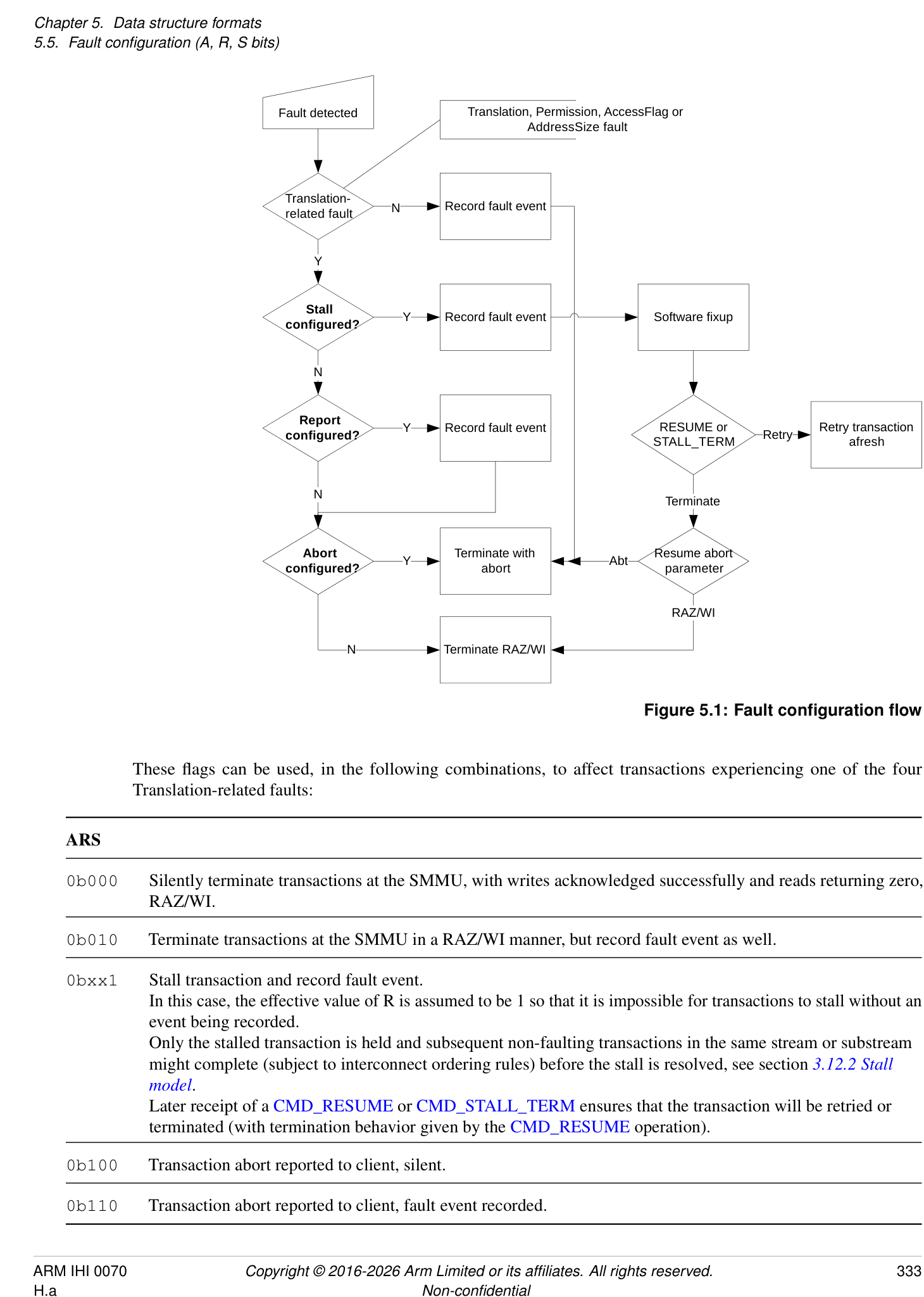
These flags can be used, in the following combinations, to affect transactions experiencing one of the four Translation-related faults:
ARS
- 0b000 Silently terminate transactions at the SMMU, with writes acknowledged successfully and reads returning zero, RAZ/WI.
0b010 Terminate transactions at the SMMU in a RAZ/WI manner, but record fault event as well.
| 0bxx1 | Stall transaction and record fault event. |
|---|---|
| In this case, the effective value of R is assumed to be 1 so that it is impossible for transactions to stall without an | |
| event being recorded. | |
| Only the stalled transaction is held and subsequent non-faulting transactions in the same stream or substream | |
| might complete (subject to interconnect ordering rules) before the stall is resolved, see section_3.12.2 Stall_ | |
| model. |
Later receipt of a CMD_RESUME or CMD_STALL_TERM ensures that the transaction will be retried or terminated (with termination behavior given by the CMD_RESUME operation).
- 0b100 Transaction abort reported to client, silent. 0b110 Transaction abort reported to client, fault event recorded.
Note: Although the STE has no A flag, stage 2 behavior is as though an effective A flag is fixed at 1.
Note: ARS == 0bxx1 is ILLEGAL when the SMMU does not support Stall behavior, or when an STE has explicitly disabled stage 1 stall configuration but stage 1 is configured to use it:
-
A CD with CD.S == 1 is considered ILLEGAL if either of the following is true:
-
SMMU_(*_)IDR0.STALL_MODEL == 0b00 and the CD is reached through an STE with STE.S1STALLD == 1.
-
SMMU_(*_)IDR0.STALL_MODEL == 0b01.
-
-
A STE with STE.S2S == 1 is considered ILLEGAL if SMMU_(*_)IDR0.STALL_MODEL == 0b01.
Note: ARS == 0bxx0 is ILLEGAL when the SMMU forces Stall behavior:
-
A CD with CD.S == 0 is considered ILLEGAL if SMMU_(*_)IDR0.STALL_MODEL == 0b10.
-
A STE with stage 2 translation enabled and STE.S2S == 0 is considered ILLEGAL if SMMU_IDR0.STALL_MODEL == 0b10.
Note: There is no separate Hit Under Previous Context Fault configuration as in prior SMMU architectures because those contain a different concept of in-register context configuration being in a stall state, whereas in SMMUv3 it is only the transaction that is stalled, separate from the configuration in memory. The treatment of stalls is therefore a per-stream or per-transaction concept rather than a per-translation context concept.
Where interconnect ordering rules allow, later transactions might overtake a stalled transaction associated with the same StreamID (and SubstreamID, if supplied with all transactions). A device might restrict ordering further if required. See section 3.12.2 Stall model for more details.
5.6 VMS, Virtual Machine Structure
The VMS characteristics are:
Purpose
Structure for per-VM configuration that can be shared across multiple StreamIDs with the same S2VMID.
Attributes
VMS is a 4096-byte structure.
Field descriptions
The Virtual Machine Structure, VMS, is an SMMU concept and is a structure that is located from the pointer field STE.VMSPtr. The VMS holds per-VM facilities. The VMS is 4KB in size and is 4KB-aligned.
Multiple STEs can point to the same VMS if required, for example to avoid duplication.
If a group of STEs with the same VMID contain different VMS pointers then it is UNPREDICTABLE which of the pointers are used for VMS access for a given STE in the group.
Note: This means that multiple STEs within a Security state with the same VMID must point to the same VMS.
The VMS is fetched using the same Security state as the STE that references it. The attributes used to access the VMS are the same as those used to fetch STEs in the corresponding Security state. See SMMU_CR1 and SMMU_STRTAB_BASE.
PARTIDMAP, bits [511:0]
Map from virtual CD.PARTID values to physical PARTID values.
Array of 32 16-bit little-endian physical PARTIDs, indexed by the virtual PARTID from CD.PARTID for a CD located through the same STE as that of the VMS.
If an entry is configured with a value that is greater than the supported PARTID size, indicated by the corresponding SMMU_(*_)MPAMIDR.PARTID_MAX, an UNKNOWN PARTID is used.
The corresponding SMMU_(*_)MPAMIDR.PARTID_MAX is chosen as follows:
-
For a Non-secure Stream, then SMMU_MPAMIDR.PARTID_MAX.
-
For a Secure Stream, if SMMU_S_MPAMIDR.HAS_MPAM_NS == 0 or STE.MPAM_NS == 0, then SMMU_S_MPAMIDR.PARTID_MAX.
-
For a Secure Stream, if SMMU_S_MPAMIDR.HAS_MPAM_NS == 1 and STE.MPAM_NS == 1, then SMMU_MPAMIDR.PARTID_MAX.
Note: There is no equivalent mapping for PMGs because they do not need to be mapped from virtual to physical values.
Note: The number 32 derives from the MPAM PE limit in the A-profile architecture[2].
Bits [32767:512]
Reserved, RES0.
The area of the VMS outside of the PARTID_MAP structure is RES0.
Note: It is the intention to use the VMS to extend the SMMU with future per-VM functionality unrelated to MPAM.
5.6.1 VMS presence and fetching
The VMS is supported by a Security state if all the statements below are true:
-
SMMU_IDR3.MPAM == 1
-
SMMU_IDR0.S1P == 1
-
SMMU_IDR0.S2P == 1
-
For Non-secure state:
- SMMU_MPAMIDR.PARTID_MAX != 0
-
For Secure state:
-
SMMU_S_IDR1.SEL2 == 1 and any of the following is true:
-
[SMMU_S_MPAMIDR][.PARTID_MAX != 0]
-
[SMMU_MPAMIDR][.PARTID_MAX != 0 and][ SMMU_S_MPAMIDR][.HAS_MPAM_NS == 1]
-
-
-
For Realm state, any of the following is true:
-
SMMU_R_MPAMIDR.PARTID_MAX != 0
-
SMMU_MPAMIDR.PARTID_MAX != 0 and SMMU_R_MPAMIDR.HAS_MPAM_NS == 1
-
The VMS is not always enabled even if an implementation supports it. See STE.VMSPtr for information on when the VMS is enabled.
If the VMS is enabled, an SMMU is permitted but not required to access the VMS when processing a transaction that uses an STE but does not require information from the VMS indicated from the STE. If this happens and the access results in an External abort, the transaction is treated as though it required the VMS and the abort is reported for the transaction as an F_VMS_FETCH event.
Note: For example, a nested configuration with STE.S1MPAM == 1 enables the VMS and the VMS is required for a transaction that undergoes both stages of translation. A different transaction using the same STE might bypass stage 1 due to STE.S1DSS == 0b01 configuration and in this case the VMS is permitted to be accessed. This means that VMS access error might be detected and reported relating to a transaction that does not require information from the VMS. See section 7.3.20 F_VMS_FETCH .
Note: It is also possible that non-client transaction accesses experience a VMS access error. See section 8.1 PRI queue overflow .
5.6.2 VMS caching and invalidation
The contents of VMS.PARTID_MAP are permitted to be cached as part of any of the following architecturally-visible structures:
-
A configuration cache entry.
-
Indexed by StreamID.
-
Invalidated by an operation affecting a StreamID, meaning an invalidation scope of CMD_CFGI_STE or wider.
-
-
A separate configuration cache for PARTID_MAP contents.
- Indexed by VMID.
PARTID_MAP information is not cached in a TLB.
Because the PARTID_MAP contents might be cached in structures indexed by StreamID and VMID, a change to PARTID_MAP requires invalidation by both StreamID and VMID.
The configuration invalidation commands CMD_CFGI_STE and CMD_CFGI_STE_RANGE invalidate cached information that is cached indexed by StreamID from all VMS fields relating to the StreamIDs in the scope of a given command.
The configuration invalidation command CMD_CFGI_ALL invalidates cached information regardless of whether it is cached indexed by StreamID or VMID.
The command CMD_CFGI_VMS_PIDM invalidates any separate caching of PARTID_MAP.
See section 4.3.5.1 Usage for more information on invalidation of VMS fields.
The VMS does not interact with SMMU_(*_)CR0.VMW. If STEs with different VMIDs point to a common VMS, information from the VMS might be cached multiple times and invalidation will require multiple operations that apply to all VMIDs that reference the VMS.
5.7 CITE, Command Queue Control Page Information Table Entry
The CITE characteristics are:
Purpose
Pointer to a vSID Translation Table (VSTT) associated with a DCMDQ control page.
Configuration
This structure is present only when SMMU_IDR6.VSID == 1. Otherwise, direct accesses to CITE are UNDEFINED.
Attributes
CITE is a 16-byte structure.
Field descriptions
127 123 122 96
SPLIT RES0
95 64
RES0
63 58 57 56 55 32
LOG2SIZE RES0 VSTT_BASE
31 3 2 1 0
VSTT_BASE RES0 V
V, bit [0]
Validity of this entry.
| V | Meaning |
|---|---|
| 0b0 | This CITE is invalid. |
| 0b1 | This CITE is valid. |
Bits [2:1]
Reserved, RES0.
VSTTBASE, bits [55:3]
Pointer to the start of the vSID Translation Table.
Bits above the implemented OA size, reported in SMMU_IDR5.OAS, are RES0.
Address bits above and below the field range are treated as 0.
Bits VSTT_BASE[N:0] are treated as 0 by the SMMU, where N == max(2, (LOG2SIZE - SPLIT - 1 + 3)). The address is therefore aligned to the larger of the VSTTE size or the L1 array size.
Bits [57:56]
Reserved, RES0.
LOG2SIZE, bits [63:58]
Table size as log2(entries).
The maximum StreamID value that can be used to index into the VSTT table is 2[LOG2SIZE] - 1. The StreamID range is equal to the number of VSTT entries in a linear VSTT table or the maximum sum of the VSTT entries in all second-level tables. The number of L1VSTTDs in the upper level of a 2-level table is MAX(1, 2[LOG2SIZE-SPLIT] ). Except for readback of a written value, the effective LOG2SIZE is <= SMMU_(R_)IDR6.VSIDSIZE for the purposes of input StreamID range checking and upper/lower/linear VSTT table index address calculation.
Bits [122:64]
Reserved, RES0.
SPLIT, bits [127:123]
When UInt(SMMUv3PAGE0.SMMUIDR0.STLEVEL) != 0:
vSID split point for multi-level table.
This field determines the split point of a 2-level VSTT table, selected by the number of bits at the bottom level.
| SPLIT | Meaning |
|---|---|
| 0b01001 | 9 bits - 4KB VSTT leaf tables. |
| 0b01011 | 11 bits - 16KB VSTT leaf tables. |
| 0b01101 | 13 bits - 64KB VSTT leaf tables. |
Other values are reserved, and behave as 0b01001.
The upper-level L1VSTTD is located using StreamID[LOG2SIZE - 1:SPLIT] and this indicates the lowest-level table which is indexed by StreamID[SPLIT - 1:0].
Note: If SPLIT >= LOG2SIZE, a single upper-level descriptor indicates one bottom-level VSTT table with 2[LOG2SIZE] usable entries. The L1VSTTD.Span value’s valid range is up to SPLIT + 1, but not all of this Span is accessible, as it is not possible to use a StreamID >= 2[LOG2SIZE] .
Otherwise:
Reserved, RES0.
5.8 L1CITD, Level 1 Command Queue Control Page Information Table Descriptor
The L1CITD characteristics are:
Purpose
Configures the base address and size of a second level Command Queue Information Table (CIT) for a range of qSIDs.
Configuration
This structure is present only when SMMU_IDR6.VSID == 1. Otherwise, direct accesses to L1CITD are UNDEFINED.
Attributes
L1CITD is a 8-byte structure.
Field descriptions
63 59 58 56 55 32
Span RES0 L2Ptr
31 4 3 0
L2Ptr RES0
Bits [3:0]
Reserved, RES0.
L2Ptr, bits [55:4]
Pointer to the start of the Level 2 CIT.
Bits above the implemented OA size, reported in SMMU_IDR5.OAS, are RES0.
Address bits above and below the field range are treated as 0.
Bits L2Ptr[N:0] are treated as 0 by the SMMU, where N == 3 + (Span - 1). The L2Ptr is therefore aligned to the size of the Level 2 CIT by the SMMU.
Bits [58:56]
Reserved, RES0.
Span, bits [63:59]
2[n] size of Level 2 array and validity of L1CIT.L2Ptr.
| Span | Meaning |
|---|---|
| 0 | L1CIT.L2Ptr is invalid. The qSIDs matching this descriptor are all invalid. |
| 1-13 | Level 2 array contains 2(Span-1) CIT entries. |
| 14-31 | Reserved, behaves as 0. |
(1) Span must be within the range of 0 to (SMMU_CITAB_BASE_CFG.SPLIT + 1), that is it must stay within the bounds of the CIT split point.
5.9 L1VSTTD, Level 1 vSID Translation Table descriptor
The L1VSTTD characteristics are:
Purpose
Configures the base address and size of a second level VSTT for a range of vSIDs.
Configuration
This structure is present only when SMMU_IDR6.VSID == 1. Otherwise, direct accesses to L1VSTTD are UNDEFINED.
Attributes
L1VSTTD is a 8-byte structure.
Field descriptions
| 63 59 | 58 56 | 55 32 | |
| Span | RES0 | L2Ptr | |
| 31 3 2 0 | |||
| L2Ptr | RES0 |
Bits [2:0]
Reserved, RES0.
L2Ptr, bits [55:3]
Pointer to the start of the Level 2 VSTT.
Bits above the implemented OA size, reported in SMMU_(R_)IDR5.OAS, are RES0.
Address bits above and below the field range are treated as 0.
Bits L2Ptr[N:0] are treated as 0 by the SMMU, where N == 2 + (Span - 1). The L2Ptr is therefore aligned to the size of the Level 2 VSTT by the SMMU.
Bits [58:56]
Reserved, RES0.
Span, bits [63:59]
2[n] size of Level 2 array and validity of L1VSTTD.L2Ptr.
| Span | Meaning |
|---|---|
| 0 | L1VSTTD.L2Ptr is invalid. A vSID matching this descriptor does not map onto a pSID and commands |
| carrying this vSID are IGNORED. | |
| 1-14 | Level 2 array contains 2(Span-1) VSTT entries. |
| 15-31 | Reserved, behaves as 0. |
(1) Span must be within the range of 0 to CITE.SPLIT, that is it must stay within the bounds of the VSTT split point.
5.10 VSTTE, vSID Translation Table Entry
The VSTTE characteristics are:
Purpose
Contains the SID of the physical device, associated with the virtual SID used to index into the VSTT.
Configuration
This structure is present only when SMMU_IDR6.VSID == 1. Otherwise, direct accesses to VSTTE are UNDEFINED.
Attributes
VSTTE is a 8-byte structure.
Field descriptions
63 32
PSID
31 1 0
RES0
PSID_VA
LID
PSIDVALID, bit [0]
Qualifier to for PSID field.
| PSID_VALID | Meaning |
|---|---|
| 0b0 | This vSID does not map onto a pSID and commands |
| carrying this vSID are IGNORED. | |
| 0b1 | This vSID maps onto a pSID and commands |
| carrying this vSID will be scoped with | |
| VSTTE.PSID. |
Bits [31:1]
Reserved, RES0.
PSID, bits [63:32]
Physical SID, translation of the virtual SID.
Memory map and registers
Chapter 6 Memory map and registers
6.1 Memory map
SMMU registers occupy two consecutive 64KB pages starting from an at least 64KB-aligned boundary. Other OPTIONAL 64KB pages might follow these pages, depending on implemented features:
-
If the VATOS interface is supported, one 64KB page is present containing the VATOS registers.
-
If the Secure VATOS interface is supported, one 64KB page is present containing the S_VATOS registers.
-
If Enhanced Command queue interfaces are supported for a Security state, one or more Command queue control pages might be present for the respective Security state, each containing one or more ECMDQ interfaces.
-
If Direct Command queue interfaces are supported for a Security state, all of the following apply:
-
One or more Direct Command queue control pages might be present for the respective Security state, each containing one or more DCMDQ interfaces.
-
One DCMDQ global page is present for the respective Security state.
-
-
Any number of IMPLEMENTATION DEFINED pages might be present.
The presence and base addresses of all OPTIONAL pages are IMPLEMENTATION DEFINED and discoverable:
-
The presence of VATOS support can be determined from SMMU_IDR0.VATOS.
-
The VATOS page’s base address is given by SMMU_IDR2.BA_VATOS.
-
This base address is called O_VATOS hereafter.
-
-
The presence of Secure VATOS support can be determined from SMMU_S_IDR1.SECURE_IMPL, SMMU_S_IDR1.SEL2 and SMMU_IDR0.VATOS.
-
The Secure VATOS page’s base address is given by SMMU_S_IDR2.BA_S_VATOS.
-
This base address is called O_S_VATOS hereafter.
-
-
The presence of Command queue control pages can be determined from SMMU_IDR1.ECMDQ, SMMU_S_IDR0.ECMDQ and SMMU_R_IDR0.ECMDQ.
-
The number of pages is discoverable from SMMU_(*_)IDR6.
-
The offset of each page is discoverable from SMMU_(*_)CMDQ_CONTROL_PAGE_BASEn.ADDR.
-
These offsets are referred to as O_(*_)CMDQCPn.
-
-
The presence of Direct Command queue control pages can be determined from SMMU_(*_)IDR6.DCMDQ.
-
The number of pages is discoverable from SMMU_(*_)IDR6.
-
The offset of each page is discoverable from SMMU_(*_)IDR8.BA_DCMDQ.
-
These offsets are referred to as O_(*_)DCMDQCPm.
-
-
The presence of a DCMDQ global page can be determined from SMMU_(*_)IDR6.DCMDQ.
-
The offset of the page is discoverable from SMMU_(*_)IDR8.BA_DCMDQ_GLOBAL.
-
The offset is referred to as O_(*_)DCMDQP_GLOBAL.
-
-
The presence of the Realm Pages 0 and 1 can be determined from SMMU_ROOT_IDR0.REALM_IMPL.
-
The offset for the Realm Page 0 is discoverable from SMMU_ROOT_IDR0.BA_REALM, and this offset is referred to as O_REALM.
-
Realm Page 1 is in the 64KB of physical address space immediately higher than Realm Page 0.
-
-
The presence of all IMPLEMENTATION DEFINED register pages can be determined through the Peripheral ID registers and IMPLEMENTATION DEFINED registers, for example SMMU_IDR4.
The base address of OPTIONAL pages is expressed as an offset from the SMMU extension address 0x20000, in units of a 64KB page.
An SMMU that does not support any OPTIONAL or IMPLEMENTATION DEFINED register pages will occupy a 128K span of addresses, 0x00000-0x1FFFF.
The values of all SMMU_R_CMDQ_CONTROL_PAGE_BASEn.ADDR are such that the pages occupy a contiguous region of address space within the SMMU register file, and they are arranged in ascending value of n. If Secure Command queue control pages are implemented, this contiguous region of address space is immediately after the contiguous region of address space for the Secure Command queue control pages.
| Offset | Register page |
|---|---|
| 0x00000-0x0FFFF | SMMU registers, Page 0 |
| 0x10000-0x1FFFF | SMMU registers, Page 1 |
| 0x20000-END | 0 or more OPTIONALpages |
| O_VATOS+ 0x0000-0xFFFF | VATOS interface registers |
| O_S_VATOS+ 0x0000-0xFFFF | Secure VATOS interface registers |
| O_CMDQCPn+ 0x0000-0xFFFF | Command queue control page n |
| O_S_CMDQCPn+ 0x0000-0xFFFF | Secure Command queue control page n |
| O_R_CMDQCPn+ 0x0000-0xFFFF | Realm Command queue control page n |
| O_DCMDQCPm+ 0x0000-0xFFFF | Direct Command queue control page m |
| O_S_DCMDQCPm+ 0x0000-0xFFFF | Secure Direct Command queue control page m |
| O_R_DCMDQCPm+ 0x0000-0xFFFF | Realm Direct Command queue control page m |
| O_DCMDQP_GLOBAL+ 0x0000-0xFFFF | DCMDQ global page |
| O_S_DCMDQP_GLOBAL+ 0x0000-0xFFFF | Secure DCMDQ global page |
| Offset | Register page |
|---|---|
| O_R_DCMDQP_GLOBAL+ 0x0000-0xFFFF | Realm DCMDQ global page |
| O_REALM+ 0x0000-0xFFFF | Realm registers, Page 0 |
| O_REALM+ 0x10000-0x1FFFF | Realm registers, Page 1 |
| IMPLEMENTATION DEFINED | Root Control Page |
6.2 Register overview
Unless specified otherwise, all registers are 32-bit, little-endian and allow read and write (R/W) accesses.
For all pages except Page 1, undefined register locations are RES0. For Page 1, access to undefined/Reserved register locations is CONSTRAINED UNPREDICTABLE and an implementation has one of the following behaviors:
-
The location has the same behavior as RES0.
-
The access has the same effect as would an access to the same offset in Page 0, that is Page 0 and 1 are permitted to alias.
The equivalent Page 0 offsets of registers that are defined on Page 1 are Reserved and Arm recommends that they are not accessed. Access to these offsets is CONSTRAINED UNPREDICTABLE and (depending on the implementation of Page 1) has one of the following behaviors:
-
The location aliases the corresponding register in Page 1.
-
The access has RAZ/WI behavior.
When SMMU_S_IDR1.SECURE_IMPL == 1, SMMU_S_* registers are RAZ/WI to Non-secure access. See section 3.11 Reset, Enable and initialization regarding Non-secure access to SMMU_S_INIT. All other registers are accessible to both Secure and Non-secure accesses.
When SMMU_S_IDR1.SECURE_IMPL == 0, SMMU_S_* registers are RES0.
In an SMMU with RME, all of the following apply:
-
All SMMU registers that are specified to be accessible only in Secure PA space in this specification are additionally accessible in Root PA space in an SMMU with RME.
-
All SMMU registers that are specified to be accessible in Non-secure PA space in this specification are additionally accessible in Root and Realm PA spaces in an SMMU with RME.
All SMMU ID registers (those that report the presence or scope of features) hold constant values after reset.
Reserved or undefined bit positions in defined registers are RES0: they read as zero and must not be written with non-zero values.
An implementation must support aligned 32-bit word access to 32-bit registers, and to both 32-bit halves of 64-bit registers. The SMMU supports aligned 64-bit access to 64-bit registers. Support for other access sizes is IMPLEMENTATION DEFINED.
The following constitute an illegal register access:
-
An access of an unsupported size.
-
Unaligned accesses, that is an access that does not start on a boundary equal to the access size.
An illegal register access is CONSTRAINED UNPREDICTABLE and has one of the following behaviors:
-
The access is RAZ/WI.
-
The access is observed by the register or registers spanned by the access and:
-
Write access will write any value to this register or registers including to fields of this register or registers outside of the access. This behavior does not enable a Non-secure access to affect registers that are not otherwise accessible to Non-secure accesses.
-
Read access returns an UNKNOWN value.
-
-
The access is terminated with an abort.
A 64-bit access to two adjacent 32-bit registers is CONSTRAINED UNPREDICTABLE and has one of the following behaviors:
-
The access is RAZ/WI.
-
A read returns the value of both registers and a write updates both registers, as though two 32-bit accesses were performed in an UNPREDICTABLE order.
-
One of the pair of registers is read or written and the other register is RAZ/WI, as though a single 32-bit access was performed to an UNPREDICTABLE one of the pair of registers.
-
The access is terminated with an abort.
Note: Arm strongly recommends not to abort accesses to registers that might be used by software that is associated with lower exception levels on the PE, such as the SMMU_VATOS_* or PMCG registers.
It is IMPLEMENTATION DEFINED whether a 64-bit access to a 64-bit register is single-copy atomic. An SMMU implementation might internally observe the access in two 32-bit halves. An aligned 32-bit word access is single-copy atomic.
All 64-bit fields are composed of two separately-writable 32-bit register halves, with bits[63:32] at offset +4 and [31:0] at offset +0.
Some register fields have a dependency on another register field, and are described as Guarded by the other field. A Guarded register field is not permitted to be changed by software unless the field by which it is Guarded is in a certain state (and is not in the process of being Updated to or from that state). For example, SMMU_CMDQ_BASE is Guarded by SMMU_CR0.CMDQEN so that software is only permitted to change SMMU_CMDQ_BASE if SMMU_CR0.CMDQEN == 0.
Note: Software must use an appropriate barrier to ensure initialization of Guarded register fields is visible to the SMMU before the SMMU observes a set of the field by which they are Guarded.
Registers are not required to support being the target of exclusive or atomic read-modify-write update operations.
In this specification, read-only means that writes are ignored.
6.2.1 Registers in Page 0
| Offset | Register | Notes |
|---|---|---|
| 0x0000 | SMMU_IDR0 | 32-bit, RO |
| 0x0004 | SMMU_IDR1 | 32-bit, RO |
| 0x0008 | SMMU_IDR2 | 32-bit, RO |
| 0x000C | SMMU_IDR3 | 32-bit, RO |
| 0x0010 | SMMU_IDR4 | 32-bit, RO |
| 0x0014 | SMMU_IDR5 | 32-bit, RO |
| 0x0018 | SMMU_IIDR | 32-bit, RO |
| 0x001C | SMMU_AIDR | 32-bit, RO |
| 0x0020 | SMMU_CR0 | 32-bit, RW |
| 0x0024 | SMMU_CR0ACK | 32-bit, RO |
| 0x0028 | SMMU_CR1 | 32-bit, RW |
| 0x002C | SMMU_CR2 | 32-bit, RW |
| 0x0030 | SMMU_S2PII | 64-bit, RW |
| Offset | Register | Notes |
|---|---|---|
| 0x0040 | SMMU_STATUSR | 32-bit, RO |
| 0x0044 | SMMU_GBPA | 32-bit, RW |
| 0x0048 | SMMU_AGBPA | 32-bit, RW |
| 0x0050 | SMMU_IRQ_CTRL | 32-bit, RW |
| 0x0054 | SMMU_IRQ_CTRLACK | 32-bit, RO |
| 0x0060 | SMMU_GERROR | 32-bit, RO |
| 0x0064 | SMMU_GERRORN | 32-bit, RW |
| 0x0068 | SMMU_GERROR_IRQ_CFG0 | 64-bit, RW |
| 0x0070 | SMMU_GERROR_IRQ_CFG1 | 32-bit, RW |
| 0x0074 | SMMU_GERROR_IRQ_CFG2 | 32-bit, RW |
| 0x0080 | SMMU_STRTAB_BASE | 64-bit, RW |
| 0x0088 | SMMU_STRTAB_BASE_CFG | 32-bit, RW |
| 0x0090 | SMMU_CMDQ_BASE | 64-bit, RW |
| 0x0098 | SMMU_CMDQ_PROD | 32-bit, RW |
| 0x009C | SMMU_CMDQ_CONS | 32-bit, RW |
| 0x00A0 | SMMU_EVENTQ_BASE | 64-bit, RW |
| 0x00A8 | Optional alias ofSMMU_EVENTQ_PROD, otherwise RAZ/WI | |
| 0x00AC | Optional alias ofSMMU_EVENTQ_CONS, otherwise RAZ/WI | |
| 0x00B0 | SMMU_EVENTQ_IRQ_CFG0 | 64-bit, RW |
| 0x00B8 | SMMU_EVENTQ_IRQ_CFG1 | 32-bit, RW |
| 0x00BC | SMMU_EVENTQ_IRQ_CFG2 | 32-bit, RW |
| 0x00C0 | SMMU_PRIQ_BASE | 64-bit, RW |
| 0x00C8 | Optional alias ofSMMU_PRIQ_PROD, otherwise RAZ/WI | 32-bit, RW |
| 0x00CC | Optional alias ofSMMU_PRIQ_CONS, otherwise RAZ/WI | 32-bit, RW |
| 0x00D0 | SMMU_PRIQ_IRQ_CFG0 | 64-bit, RW |
| 0x00D8 | SMMU_PRIQ_IRQ_CFG1 | 32-bit, RW |
| 0x00DC | SMMU_PRIQ_IRQ_CFG2 | 32-bit, RW |
| Offset | Register | Notes |
|---|---|---|
| 0x0100 | SMMU_GATOS_CTRL | 32-bit, RW |
| 0x0108 | SMMU_GATOS_SID | 64-bit, RW |
| 0x0110 | SMMU_GATOS_ADDR | 64-bit, RW |
| 0x0118 | SMMU_GATOS_PAR | 64-bit, RO |
| 0x0130 | SMMU_MPAMIDR | 32-bit, RO |
| 0x0138 | SMMU_GMPAM | 32-bit, RW |
| 0x013C | SMMU_GBPMPAM | 32-bit, RW |
| 0x0180 | SMMU_VATOS_SEL | 32-bit, RW |
| 0x0190 | SMMU_IDR6 | 32-bit, RO |
| 0x0194 | SMMU_IDR7 | 32-bit, RO |
| 0x0198 | SMMU_IDR8 | 32-bit, RO |
| 0x0200 | SMMU_DPT_BASE | 64-bit, RW |
| 0x0208 | SMMU_DPT_BASE_CFG | 32-bit, RW |
| 0x0210 | SMMU_DPT_CFG_FAR | 64-bit, RW |
| 0x0220 | SMMU_MECIDR | 32-bit, RO |
| 0x0240 | SMMU_HDBSS_BASE0 | 64-bit, RW |
| 0x0248 | SMMU_HDBSS_PROD0 | 64-bit, RW |
| 0x0250 | SMMU_HDBSS_BASE1 | 64-bit, RW |
| 0x0258 | SMMU_HDBSS_PROD1 | 64-bit, RW |
| 0x0260 | SMMU_HDBSS_IRQ_CFG0 | 64-bit, RW |
| 0x0268 | SMMU_HDBSS_IRQ_CFG1 | 32-bit, RW |
| 0x026C | SMMU_HDBSS_IRQ_CFG2 | 32-bit, RW |
| 0x0270 | SMMU_HDBSS_MPAM | 32-bit, RW |
| 0x0440 | SMMU_HACDBS_BASE | 64-bit, RW |
| 0x0448 | SMMU_HACDBS_CONS | 64-bit, RW |
| 0x0450 | SMMU_HACDBS_IRQ_CFG0 | 64-bit, RO |
| 0x0458 | SMMU_HACDBS_IRQ_CFG1 | 32-bit, RO |
| Offset | Register | Notes |
|---|---|---|
| 0x045C | SMMU_HACDBS_IRQ_CFG2 | 32-bit, RO |
| 0x0460 | SMMU_HACDBS_MPAM | 32-bit, RW |
| 0x0540 | SMMU_CITAB_BASE | 64-bit, RW |
| 0x0548 | SMMU_CITAB_BASE_CFG | 32-bit, RW |
| 0x0E00 | IMPLEMENTATION DEFINED | IMPLEMENTATION DEFINED |
| - | ||
| 0x0EFF | ||
| 0x0FD0- | ID_REGS- identifcation register space. | IMPLEMENTATION DEFINED |
| 0x0FFC | ||
| 0x1000 | IMPLEMENTATION DEFINED | IMPLEMENTATION DEFINED |
| - | ||
| 0x3FFF | ||
| 0x4000 | SMMU_CMDQ_CONTROL_PAGE_BASEn | 64-bit, RO |
| + 32*n | ||
| 0x4008 | SMMU_CMDQ_CONTROL_PAGE_CFGn | 32-bit, RO |
| + 32*n | ||
| 0x400C | SMMU_CMDQ_CONTROL_PAGE_STATUSn | 32-bit, RO |
| + 32*n | ||
| 0x8000 | SMMU_S_IDR0 | 32-bit, Secure, RO |
| 0x8004 | SMMU_S_IDR1 | 32-bit, Secure, RO |
| 0x8008 | SMMU_S_IDR2 | 32-bit, Secure, RO |
| 0x800C | SMMU_S_IDR3 | 32-bit, Secure, RO |
| 0x8010 | SMMU_S_IDR4 | 32-bit, Secure, RO |
| 0x8020 | SMMU_S_CR0 | 32-bit, Secure, RW |
| 0x8024 | SMMU_S_CR0ACK | 32-bit, Secure, RO |
| 0x8028 | SMMU_S_CR1 | 32-bit, Secure, RW |
| 0x802C | SMMU_S_CR2 | 32-bit, Secure, RW |
| 0x8030 | SMMU_S_S2PII | 64-bit, Secure, RW |
| 0x803C | SMMU_S_INIT | 32-bit, Secure, RW |
| 0x8044 | SMMU_S_GBPA | 32-bit, Secure, RW |
| 0x8048 | SMMU_S_AGBPA | 32-bit, Secure, RW |
| Offset | Register | Notes |
|---|---|---|
| 0x8050 | SMMU_S_IRQ_CTRL | 32-bit, Secure, RW |
| 0x8054 | SMMU_S_IRQ_CTRLACK | 32-bit, Secure, RO |
| 0x8060 | SMMU_S_GERROR | 32-bit, Secure, RO |
| 0x8064 | SMMU_S_GERRORN | 32-bit, Secure, RW |
| 0x8068 | SMMU_S_GERROR_IRQ_CFG0 | 64-bit, Secure, RW |
| 0x8070 | SMMU_S_GERROR_IRQ_CFG1 | 32-bit, Secure, RW |
| 0x8074 | SMMU_S_GERROR_IRQ_CFG2 | 32-bit, Secure, RW |
| 0x8080 | SMMU_S_STRTAB_BASE | 64-bit, Secure, RW |
| 0x8088 | SMMU_S_STRTAB_BASE_CFG | 32-bit, Secure, RW |
| 0x8090 | SMMU_S_CMDQ_BASE | 64-bit, Secure, RW |
| 0x8098 | SMMU_S_CMDQ_PROD | 32-bit, Secure, RW |
| 0x809C | SMMU_S_CMDQ_CONS | 32-bit, Secure, RW |
| 0x80A0 | SMMU_S_EVENTQ_BASE | 64-bit, Secure, RW |
| 0x80A8 | SMMU_S_EVENTQ_PROD | 32-bit, Secure, RW |
| 0x80AC | SMMU_S_EVENTQ_CONS | 32-bit, Secure, RW |
| 0x80B0 | SMMU_S_EVENTQ_IRQ_CFG0 | 64-bit, Secure, RW |
| 0x80B8 | SMMU_S_EVENTQ_IRQ_CFG1 | 32-bit, Secure, RW |
| 0x80BC | SMMU_S_EVENTQ_IRQ_CFG2 | 32-bit, Secure, RW |
| 0x8100 | SMMU_S_GATOS_CTRL | 32-bit, Secure, RW |
| 0x8108 | SMMU_S_GATOS_SID | 64-bit, Secure, RW |
| 0x8110 | SMMU_S_GATOS_ADDR | 64-bit, Secure, RW |
| 0x8118 | SMMU_S_GATOS_PAR | 64-bit, Secure, RO |
| 0x8130 | SMMU_S_MPAMIDR | 32-bit, Secure, RO |
| 0x8138 | SMMU_S_GMPAM | 32-bit, Secure, RW |
| 0x813C | SMMU_S_GBPMPAM | 32-bit, Secure, RW |
| 0x8180 | SMMU_S_VATOS_SEL | 32-bit, Secure, RW |
| 0x8190 | SMMU_S_IDR6 | 32-bit, Secure, RO |
| Offset | Register | Notes |
|---|---|---|
| 0x8194 | SMMU_S_IDR7 | 32-bit, RO |
| 0x8198 | SMMU_S_IDR8 | 32-bit, RO |
| 0x8240 | SMMU_S_HDBSS_BASE0 | 64-bit, RW |
| 0x8248 | SMMU_S_HDBSS_PROD0 | 64-bit, RW |
| 0x8250 | SMMU_S_HDBSS_BASE1 | 64-bit, RW |
| 0x8258 | SMMU_S_HDBSS_PROD1 | 64-bit, RW |
| 0x8260 | SMMU_S_HDBSS_IRQ_CFG0 | 64-bit, RW |
| 0x8268 | SMMU_S_HDBSS_IRQ_CFG1 | 32-bit, RW |
| 0x826C | SMMU_S_HDBSS_IRQ_CFG2 | 32-bit, RW |
| 0x8270 | SMMU_S_HDBSS_MPAM | 32-bit, RW |
| 0x8440 | SMMU_S_HACDBS_BASE | 64-bit, RW |
| 0x8448 | SMMU_S_HACDBS_CONS | 64-bit, RW |
| 0x8450 | SMMU_S_HACDBS_IRQ_CFG0 | 64-bit, RO |
| 0x8458 | SMMU_S_HACDBS_IRQ_CFG1 | 32-bit, RO |
| 0x845C | SMMU_S_HACDBS_IRQ_CFG2 | 32-bit, RO |
| 0x8460 | SMMU_S_HACDBS_MPAM | 32-bit, RW |
| 0x8E00 | IMPLEMENTATION DEFINED, Secure | IMPLEMENTATION DEFINED, |
| - | Secure | |
| 0x8EFF | ||
| 0x9000 | IMPLEMENTATION DEFINED, Secure | IMPLEMENTATION DEFINED, |
| - | Secure | |
| 0xBFFF | ||
| 0xC000 | SMMU_S_CMDQ_CONTROL_PAGE_BASEn | 64-bit, Secure, RO |
| + 32*n | ||
| 0xC008 | SMMU_S_CMDQ_CONTROL_PAGE_CFGn | 32-bit, Secure, RO |
| + 32*n | ||
| 0xC00C | SMMU_S_CMDQ_CONTROL_PAGE_STATUSn | 32-bit, Secure, RO |
| + 32*n |
6.2.2 Registers in Page 1
Offsets are relative to the base of Page 1, 0x10000.
| Offset | Register | Notes |
|---|---|---|
| 0x00A8 | SMMU_EVENTQ_PROD | 32-bit, RW |
| 0x00AC | SMMU_EVENTQ_CONS | 32-bit, RW |
| 0x00C8 | SMMU_PRIQ_PROD | 32-bit, RW |
| 0x00CC | SMMU_PRIQ_CONS | 32-bit, RW |
6.2.3 Registers in the VATOS page
When SMMU_IDR0.VATOS == 1, the VATOS page is present.
Offsets are relative to the base of the VATOS page, O_VATOS. See SMMU_IDR2.
| Offset | Register | Notes |
|---|---|---|
| 0x0A00 | SMMU_VATOS_CTRL | 32-bit, RW |
| 0x0A08 | SMMU_VATOS_SID | 64-bit, RW |
| 0x0A10 | SMMU_VATOS_ADDR | 64-bit, RW |
| 0x0A18 | SMMU_VATOS_PAR | 64-bit, RO |
| 0x0E00 | IMPLEMENTATION DEFINED | |
| - | ||
| 0x0EFF |
6.2.4 Registers in the S_VATOS page
When Secure state is supported and SMMU_S_IDR1.SEL2 == 1 and SMMU_IDR0.VATOS == 1, the S_VATOS page is present.
The base address of the S_VATOS page is determined from SMMU_S_IDR2.BA_S_VATOS and referred to as O_S_VATOS:
O_S_VATOS = SMMU_BASE + 0x20000 + (SMMU_S_IDR2.BA_S_VATOS * 0x10000)
The offsets below are relative to the base of the S_VATOS page, O_S_VATOS.
| Offset | Register | Notes |
|---|---|---|
| 0x0A00 | SMMU_S_VATOS_CTRL | 32-bit, Secure, RW |
| 0x0A08 | SMMU_S_VATOS_SID | 64-bit, Secure, RW |
| 0x0A10 | SMMU_S_VATOS_ADDR | 64-bit, Secure, RW |
| 0x0A18 | SMMU_S_VATOS_PAR | 64-bit, Secure, RO |
| Offset | Register | Notes | |
|---|---|---|---|
| 0x0E00 | IMPLEMENTATION | DEFINED | Secure |
| - | |||
| 0x0EFF |
6.2.5 Registers in a Command queue control page
When SMMU_IDR1.ECMDQ, SMMU_S_IDR0.ECMDQ or SMMU_R_IDR0.ECMDQ are 1, one or more Command queue control pages are present in the respective security state.
A Command queue control page contains the ECMDQ interfaces specified in section 3.5.6 Enhanced Command queue interfaces .
The number of ECMDQ interfaces in an ECMDQ control page is determined by the value of SMMU_(*_)IDR6.CMDQ_CONTROL_PAGE_LOG2NUMQ.
The size of a Command queue control page is 64KB. A Command queue control page is aligned in PA space to 64KB.
A Command queue control page is implemented as a set of registers.
The ECMDQ interfaces are spaced evenly throughout a Command queue control page.
For example, if a control page has 128 ECMDQs, the interfaces are spaced at 512-byte intervals throughout the page.
A Command queue control page therefore has 2[(][SMMU_(*_)IDR6][.CMDQ_CONTROL_PAGE_LOG2NUMQ)] copies of the following three registers, as shown below for ECMDQ n :
| Offset | Register | Notes |
|---|---|---|
| 0x00 + ((2^(16 - SMMU_IDR6.CMDQ_CONTROL_PAGE_LOG2NUMQ))* n) | SMMU_(*_)ECMDQ_BASEn | 64-bit, R/W |
| 0x08 + ((2^(16 - SMMU_IDR6.CMDQ_CONTROL_PAGE_LOG2NUMQ))* n) | SMMU_(*_)ECMDQ_PRODn | 32-bit, R/W |
| 0x0C + ((2^(16 - SMMU_IDR6.CMDQ_CONTROL_PAGE_LOG2NUMQ))* n) | SMMU_(*_)ECMDQ_CONSn | 32-bit, R/W |
6.2.6 Registers in a Direct Command queue control page
When SMMU_(*_)IDR6.DCMDQ is 0b01, one or more Direct Command queue control pages are present in the respective security state.
A Direct Command queue control page contains the DCMDQ interfaces specified in section 3.5.7.1 Configuration of ECMDQ and DCMDQ interfaces .
The number of DCMDQ interfaces in a DCMDQ control page is determined by the value of SMMU_(*_)IDR6.DCMDQ_CONTROL_PAGE_LOG2NUMQ.
The size of a Direct Command queue control page is 64KB. A Direct Command queue control page is aligned in PA space to 64KB.
A Direct Command queue control page is implemented as a set of registers.
The DCMDQ interfaces are spaced evenly throughout a Direct Command queue control page.
For example, if a control page has 128 DCMDQs, the interfaces are spaced at 512-byte intervals throughout the page.
A Direct Command queue control page therefore has 2[(][SMMU_(*_)IDR6][.DCMDQ_CONTROL_PAGE_LOG2NUMQ)] copies of the following three registers, as shown below for DCMDQ n :
| Offset | Register | Notes |
|---|---|---|
| 0x00 + ((2^(16 - SMMU_IDR6.DCMDQ_CONTROL_PAGE_LOG2NUMQ))* n) | SMMU_(*_)DCMDQ_BASEn | 64-bit, R/W |
| 0x08 + ((2^(16 - SMMU_IDR6.DCMDQ_CONTROL_PAGE_LOG2NUMQ))* n) | SMMU_(*_)DCMDQ_PRODn | 32-bit, R/W |
| 0x0C + ((2^(16 - SMMU_IDR6.DCMDQ_CONTROL_PAGE_LOG2NUMQ))* n) | SMMU_(*_)DCMDQ_CONSn | 32-bit, R/W |
6.2.7 Registers in a DCMDQ global page
When SMMU_(*_)IDR6.DCMDQ is 0b01, one DCMDQ global page is present in the respective security state. A DCMDQ global page has the following registers:
| Offset | Register | Notes | ||||
|---|---|---|---|---|---|---|
| 0x0000 | + | (0x8 | * | n) | SMMU_(*_)DCMDQP_ERRn | 64-bit, RO |
| 0xE000 | + | (0x8 | * | n) | SMMU_(*_)DCMDQP_ERRNn | 64-bit, R/W |
6.2.8 Root Control Page
When SMMU_ROOT_IDR0.ROOT_IMPL == 1, the SMMU Root Control Page is present.
Access to the SMMU Root Control Page is bounded by the following rules:
-
The base address is IMPLEMENTATION DEFINED.
-
The base address is 64KB aligned.
-
The page is accessible only in the Root PA space.
-
Accesses in any PA space other than Root are completed as RAZ/WI.
-
The Root Control Page base address is distinct from addresses of registers accessible in other PA spaces.
Address map:
| Offset | Register | Notes | |
|---|---|---|---|
| 0x0000 | SMMU_ROOT_IDR0 | 32-bit, RO | |
| 0x0008 | SMMU_ROOT_IIDR | 32-bit, RO | |
| 0x0020 | SMMU_ROOT_CR0 | 32-bit, R/W | |
| 0x0024 | SMMU_ROOT_CR0ACK | 32-bit, RO | |
| 0x0028 | SMMU_ROOT_GPT_BASE | 64-bit, R/W | |
| 0x0030 | SMMU_ROOT_GPT_BASE_CFG | 64-bit, R/W | |
| 0x0038 | SMMU_ROOT_GPF_FAR | 64-bit, R/W | |
| 0x0040 | SMMU_ROOT_GPT_CFG_FAR | 64-bit, R/W | |
| 0x0050 | SMMU_ROOT_TLBI | 64-bit, R/W, | OPTIONAL |
| 0x0058 | SMMU_ROOT_TLBI_CTRL | 32-bit, R/W, | OPTIONAL |
| 0x0060 | SMMU_ROOT_GPT_BASE2 | 64-bit, R/W |
| Offset | Register | Notes |
|---|---|---|
| 0x0068 | SMMU_ROOT_GPT_BASE_UPDATE | 32-bit, R/W |
| 0x0070 | SMMU_ROOT_GPCBW | 64-bit, R/W |
| 0x0E00-0x0EFF | IMPLEMENTATION DEFINED | IMPLEMENTATION DEFINED |
Locations in the SMMU Root Control Page that are not associated with a register are RES0.
6.2.9 Realm Register Pages
The two SMMUv3 Realm Register Pages have the following properties:
-
The two pages are adjacent and together occupy a naturally-aligned 128KB region of physical address space.
-
The registers are only accessible in Realm and Root PA spaces. Non-secure and Secure accesses to the page are RAZ/WI.
-
Addresses configured in these registers are treated as Realm physical addresses by default. Some of the configuration registers have an NS override bit, which selects Non-secure physical address space if set.
-
If SMMU_IDR1.QUEUES_PRESET is 1 and SMMU_IDR1.REL is 1, then the preset address values in all of the SMMU_R_{CMDQ,EVENTQ,PRIQ}_BASE registers are relative to the base address of the Non-secure SMMU register Page 0.
-
If SMMU_IDR1.TABLES_PRESET is 1 and SMMU_IDR1.REL is 1, then the preset address value in the SMMU_R_STRTAB_BASE register is relative to the base address of the Non-secure SMMU register Page 0.
6.2.10 Registers in Realm Page 0
When SMMU_ROOT_IDR0.REALM_IMPL == 1, the SMMU Realm Page 0 is present.
The layout of Realm Page 0 is as follows:
| Offset | Register name | Notes |
|---|---|---|
| 0x0000 | SMMU_R_IDR0 | 32-bit, RO |
| 0x0004 | SMMU_R_IDR1 | 32-bit, RO |
| 0x0008 | SMMU_R_IDR2 | 32-bit, RO |
| 0x000C | SMMU_R_IDR3 | 32-bit, RO |
| 0x0010 | SMMU_R_IDR4 | 32-bit, RO |
| 0x0018 | Reserved, RES0. | Implementation identifcation is described in |
| SMMU_IIDR. There is no SMMU_R_IIDR | ||
| register. | ||
| 0x001C | SMMU_R_AIDR | 32-bit, RO |
| 0x0020 | SMMU_R_CR0 | 32-bit, RW |
| 0x0024 | SMMU_R_CR0ACK | 32-bit, RO |
| 0x0028 | SMMU_R_CR1 | 32-bit, RW |
| 0x002C | SMMU_R_CR2 | 32-bit, RW |
| 0x0030 | SMMU_R_S2PII | 64-bit, RW |
| 0x0044 | SMMU_R_GBPA | 32-bit, RO |
| 0x0048 | SMMU_R_AGBPA | 32-bit, RW |
| 0x0050 | SMMU_R_IRQ_CTRL | 32-bit, RW |
|---|---|---|
| 0x0054 | SMMU_R_IRQ_CTRLACK | 32-bit, RO |
| 0x0060 | SMMU_R_GERROR | 32-bit, RO |
| 0x0064 | SMMU_R_GERRORN | 32-bit, RW |
| 0x0068 | SMMU_R_GERROR_IRQ_CFG0 | 64-bit, RW |
| 0x0070 | SMMU_R_GERROR_IRQ_CFG1 | 32-bit, RW |
| 0x0074 | SMMU_R_GERROR_IRQ_CFG2 | 32-bit, RW |
| 0x0080 | SMMU_R_STRTAB_BASE | 64-bit, RW |
| 0x0088 | SMMU_R_STRTAB_BASE_CFG | 32-bit, RW |
| 0x0090 | SMMU_R_CMDQ_BASE | 64-bit, RW |
| 0x0098 | SMMU_R_CMDQ_PROD | 32-bit, RW |
| 0x009C | SMMU_R_CMDQ_CONS | 32-bit, RW |
| 0x00A0 | SMMU_R_EVENTQ_BASE | 64-bit, RW |
| 0x00A8 | Optional alias ofSMMU_R_EVENTQ_PROD. | |
| 0x00AC | Optional alias ofSMMU_R_EVENTQ_CONS. | |
| 0x00B0 | SMMU_R_EVENTQ_IRQ_CFG0 | 64-bit, RW |
| 0x00B8 | SMMU_R_EVENTQ_IRQ_CFG1 | 32-bit, RW |
| 0x00BC | SMMU_R_EVENTQ_IRQ_CFG2 | 32-bit, RW |
| 0x00C0 | SMMU_R_PRIQ_BASE | 64-bit, RW |
| 0x00C8 | Optional alias ofSMMU_R_PRIQ_PROD. | |
| 0x00CC | Optional alias ofSMMU_R_PRIQ_CONS. | |
| 0x00D0 | SMMU_R_PRIQ_IRQ_CFG0 | 64-bit, RW |
| 0x00D8 | SMMU_R_PRIQ_IRQ_CFG1 | 32-bit, RW |
| 0x00DC | SMMU_R_PRIQ_IRQ_CFG2 | 32-bit, RW |
| 0x0130 | SMMU_R_MPAMIDR | 32-bit, RO |
| 0x0138 | SMMU_R_GMPAM | 32-bit, RW |
| 0x013C | Reserved, RES0 | SMMU_R_GBPA.ABORT and |
| SMMU_R_CR0.ATSCHK are RES1, therefore | ||
| there is no need for an SMMU_R_GBPMPAM | ||
| register. | ||
| 0x0190 | SMMU_R_IDR6 | 32-bit, RO |
| 0x0194 | SMMU_R_IDR7 | 32-bit, RO |
| 0x0198 | SMMU_R_IDR8 | 32-bit, RO |
| 0x0200 | SMMU_R_DPT_BASE | 64-bit, RW |
| 0x0208 | SMMU_R_DPT_BASE_CFG | 32-bit, RW |
| 0x0210 | SMMU_R_DPT_CFG_FAR | 64-bit, RW |
| 0x0220 | SMMU_R_MECIDR | 32-bit, RO |
| 0x0228 | SMMU_R_GMECID | 32-bit, RO |
|---|---|---|
| 0x0240 | SMMU_R_HDBSS_BASE0 | 64-bit, RW |
| 0x0248 | SMMU_R_HDBSS_PROD0 | 64-bit, RW |
| 0x0250 | SMMU_R_HDBSS_BASE1 | 64-bit, RW |
| 0x0258 | SMMU_R_HDBSS_PROD1 | 64-bit, RW |
| 0x0260 | SMMU_R_HDBSS_IRQ_CFG0 | 64-bit, RW |
| 0x0268 | SMMU_R_HDBSS_IRQ_CFG1 | 32-bit, RW |
| 0x026C | SMMU_R_HDBSS_IRQ_CFG2 | 32-bit, RW |
| 0x0270 | SMMU_R_HDBSS_MPAM | 32-bit, RW |
| 0x0274 | SMMU_R_HDBSS_MECID | 32-bit, RW |
| 0x0440 | SMMU_R_HACDBS_BASE | 64-bit, RW |
| 0x0448 | SMMU_R_HACDBS_CONS | 64-bit, RW |
| 0x0450 | SMMU_R_HACDBS_IRQ_CFG0 | 64-bit, RO |
| 0x0458 | SMMU_R_HACDBS_IRQ_CFG1 | 32-bit, RO |
| 0x045C | SMMU_R_HACDBS_IRQ_CFG2 | 32-bit, RO |
| 0x0460 | SMMU_R_HACDBS_MPAM | 32-bit, RW |
| 0x0464 | SMMU_R_HACDBS_MECID | 32-bit, RW |
| 0x0540 | SMMU_R_CITAB_BASE | 64-bit, RW |
| 0x0548 | SMMU_R_CITAB_BASE_CFG | 32-bit, RW |
| 0x4000 + | SMMU_R_CMDQ_CONTROL_PAGE_BASEn | 64-bit, RO |
| (32*n) | ||
| 0x4008 + | SMMU_R_CMDQ_CONTROL_PAGE_CFGn | 32-bit, RO |
| (32*n) | ||
| 0x400C + | SMMU_R_CMDQ_CONTROL_PAGE_STATUSn | 32-bit, RO |
| (32*n) | ||
| 0x0E00to 0x0EFF | IMPLEMENTATION DEFINED | IMPLEMENTATION DEFINED |
6.2.11 Registers in Realm Page 1
When SMMU_ROOT_IDR0.REALM_IMPL == 1, the SMMU Realm Page 1 is present.
The layout of Realm Page 1 is as follows:
| Offset | Register name | Details |
|---|---|---|
| 0x00A8 | SMMU_R_EVENTQ_PROD | Equivalent toSMMU_EVENTQ_PROD. |
| 0x00AC | SMMU_R_EVENTQ_CONS | Equivalent toSMMU_EVENTQ_CONS. |
| 0x00C8 | SMMU_R_PRIQ_PROD | Equivalent toSMMU_PRIQ_PROD. |
| 0x00CC | SMMU_R_PRIQ_CONS | Equivalent toSMMU_PRIQ_CONS. |
6.3 Register formats
In the following detailed register descriptions, there is information about behavior of accesses to each register. For each register, there is a subsection titled “Accessing the register name ”. This subsection in each register description follows the following format:
-
Optional introductory text, that might specify complex access behaviors.
-
A table describing the register page and offset of the register.
-
A simplified description of the register access behavior.
In all cases, the information in part 3 describes the behavior from SMMUv3.2 onwards. In some cases, the introductory text in part 1 includes additional, more-relaxed, behaviors that were permitted in SMMUv3.1 and earlier.
6.3.1 SMMU_IDR0
The SMMU_IDR0 characteristics are:
Purpose
Provides information about the features implemented for the SMMU Non-secure programming interface.
Configuration
There are no configuration notes.
Attributes
SMMU_IDR0 is a 32-bit register.
This register is part of the SMMUv3_PAGE_0 block.
Field descriptions
31 30 29 28 27 26 25 24 23 22 21 20 19 18 17 16 15 14 13 12 11 10 9 8 7 6 5 4 3 2 1 0
VMWPRI SEVMSI ATSHyp HTTU BTM TTF S1PS2P
RES0 COHACC
RME_IMPL DORMHINT
RES0 NS1ATS
ST_LEVEL ASID16
TERM_MODEL ATOS
STALL_MODEL VMID16
ATSRECERR CD2L
TTENDIAN VATOS
Bit [31]
Reserved, RES0.
RMEIMPL, bit [30]
Indicates support for SMMUv3.3-RME_IMPL.
The value of this field is an IMPLEMENTATION DEFINED choice of:
| RME_IMPL | Meaning |
|---|---|
| 0b0 | RME features not supported for Non-secure, Secure or |
| Realm programming interfaces. | |
| 0b1 | RME features supported for Non-secure programming |
| interface, for Secure programming interface if implemented, | |
| and for Realm programming interface if implemented. |
If this field is 1, it is possible to report each of F_STE_FETCH, F_CD_FETCH, F_VMS_FETCH, and F_WALK_EABT with GPCF == 1 in Event queues.
If this field is 1, then SMMU_ROOT_IDR0.ROOT_IMPL is 1.
Access to this field is RO.
Bit [29]
Reserved, RES0.
STLEVEL, bits [28:27]
Multi-level Stream table support.
The value of this field is an IMPLEMENTATION DEFINED choice of:
| ST_LEVEL | Meaning |
|---|---|
| 0b00 | Linear Stream table supported. |
| 0b01 | 2-level Stream table supported in addition to Linear |
| Stream table. |
All other values are reserved.
Access to this field is RO.
TERMMODEL, bit [26]
Terminate model behavior.
The value of this field is an IMPLEMENTATION DEFINED choice of:
| TERM_MODEL | Meaning |
|---|---|
| 0b0 | CD.Afag determines Abort or RAZ/WI behavior of a |
| terminated transaction. | |
| • The act of terminating a transaction might be | |
| confgured using the CD.A fag to successfully | |
| complete the transaction with RAZ/WI behavior | |
| or abort the transaction. | |
| 0b1 | Terminating a transaction with RAZ/WI behavior is |
| not supported,CD.Amust be 1. | |
| • This means that a terminated transaction will | |
| always be aborted. |
Access to this field is RO.
STALLMODEL, bits [25:24]
Stall model support.
When SMMUSIDR1.SECUREIMPL == 0:
The value of this field is an IMPLEMENTATION DEFINED choice of:
| STALL_MODEL | Meaning |
|---|---|
| 0b00 | Stall and Terminate models supported. |
| 0b01 | Stall is not supported, all faults terminate transaction |
| andSTE.S2SandCD.Smust be 0. | |
| • CMD_RESUMEandCMD_STALL_TERMare | |
| not available. | |
| 0b10 | Stall is forced (all faults eligible to stall cause stall), |
| STE.S2SandCD.Smust be 1. |
All other values are reserved.
This field reports whether an implementation supports the Stall model.
-
Note: STE.S2S must be in the states above only if stage 2 translation was enabled.
-
Note: An SMMU associated with a PCI system must not have STALL_MODEL == 0b10.
Access to this field is RO.
Otherwise:
This field reports SMMU_S_IDR0.STALL_MODEL unless SMMU_S_IDR0.STALL_MODEL == 0b00 and SMMU_S_CR0.NSSTALLD == 1 in which case Non-secure use of Stall is prevented and this field’s value is 0b01.
See section 3.12 Fault models, recording and reporting .
Access to this field is RO.
ATSRECERR, bit [23]
Indicates support for recording Configuration-related errors for ATS and PRI.
The value of this field is an IMPLEMENTATION DEFINED choice of:
| ATSRECERR | Meaning |
|---|---|
| 0b0 | SMMU supports recording only the base set of Events |
| for ATS-related and PRI requests. | |
| 0b1 | SMMU supports recording some additional Events for |
| ATS-related and PRI requests. |
See section 3.9.1.2 Responses to ATS Translation Requests and section 8.1 PRI queue overflow for details of which events are recorded or not.
See SMMU_CR2.REC_CFG_ATS for control details.
This bit is RES0 if SMMU_IDR0.ATS == 0.
Access to this field is RO.
TTENDIAN, bits [22:21]
Endianness support for translation table walks.
The value of this field is an IMPLEMENTATION DEFINED choice of:
| TTENDIAN | Meaning |
|---|---|
| 0b00 | Mixed-endian: CD.ENDIandSTE.S2ENDIare each permitted |
| to select either endianness, and do not have to have the same | |
| value | |
| 0b10 | Little-endian: CD.ENDIandSTE.S2ENDImust select |
| little-endian | |
| 0b11 | Big-endian: CD.ENDIandSTE.S2ENDImust select |
| big-endian |
All other values are reserved.
- Arm strongly recommends that a general-purpose SMMU implementation supports mixed-endian translation table walks.
Access to this field is RO.
VATOS, bit [20]
Virtual ATOS page interface supported.
The value of this field is an IMPLEMENTATION DEFINED choice of:
| VATOS | Meaning |
|---|---|
| 0b0 | Virtual ATOS page interface not supported. |
| 0b1 | Virtual ATOS page interface supported. |
| • ATOS must also be supported | |
| • Stage 1 and stage 2 translation must also be supported. |
Access to this field is RO.
CD2L, bit [19]
- 2-level Context descriptor table supported.
The value of this field is an IMPLEMENTATION DEFINED choice of:
| CD2L | Meaning |
|---|---|
| 0b0 | 2-level CD table not supported. |
| 0b1 | 2-level CD table supported. |
Access to this field is RO.
VMID16, bit [18]
- 16-bit VMID supported.
The value of this field is an IMPLEMENTATION DEFINED choice of:
| VMID16 | Meaning |
|---|---|
| 0b0 | 16-bit VMID not supported. |
| • VMID[15:8] is RES0 in command parameters and must be | |
| zero inSTE.S2VMID. | |
| 0b1 | 16-bit VMID supported. |
- Note: The value of this field is irrelevant to software unless SMMU_IDR0.S2P == 1.
Access to this field is RO.
VMW, bit [17]
VMID wildcard-matching supported for TLB invalidation.
The value of this field is an IMPLEMENTATION DEFINED choice of:
| VMW | Meaning |
|---|---|
| 0b0 | VMID wildcard-matching not supported for TLB invalidation. |
| 0b1 | VMID wildcard-matching supported for TLB invalidation. |
- When SMMU_IDR0.S2P == 0 this field is RES0
Access to this field is RO.
PRI, bit [16]
Page Request Interface supported.
The value of this field is an IMPLEMENTATION DEFINED choice of:
| PRI | Meaning |
|---|---|
| 0b0 | Page Request Interface not supported |
| • All SMMU_PRIQ_* registers are Reserved. | |
| 0b1 | Page Request Interface supported |
-
When SMMU_IDR0.ATS == 0 this field is RES0.
-
See section 3.9 Support for PCI Express, PASIDs, PRI, and ATS .
Access to this field is RO.
ATOS, bit [15]
Address Translation Operations supported.
The value of this field is an IMPLEMENTATION DEFINED choice of:
| ATOS | Meaning |
|---|---|
| 0b0 | Address Translation Operations not supported. |
| • SMMU_IDR0.VATOS is RES0 and all SMMU_(S_)GATOS_* registers | |
| are Reserved. | |
| 0b1 | Address Translation Operations supported |
Access to this field is RO.
SEV, bit [14]
SMMU, and system, support generation of WFE wake-up events to PE.
The value of this field is an IMPLEMENTATION DEFINED choice of:
| SEV | Meaning |
|---|---|
| 0b0 | SMMU, and system, do not support generation of WFE wake-up events to PE. |
| 0b1 | SMMU, and system, support generation of WFE wake-up events to PE. |
| • Note: WFE might be used on the PE to wait forCMD_SYNCcommand | |
| completion. |
- This bit must reflect the ability of the system, and SMMU implementation, to convey events to all PEs that are expected to run SMMU maintenance software.
Access to this field is RO.
MSI, bit [13]
Message Signalled Interrupts are supported.
The value of this field is an IMPLEMENTATION DEFINED choice of:
| MSI | Meaning |
|---|---|
| 0b0 | The implementation supports wired interrupt notifcations only. |
| • The MSI felds in SMMU_EVENTQ_IRQ_CFGn, | |
| SMMU_PRIQ_IRQ_CFGn and SMMU_GERROR_IRQ_CFGn are RES0. | |
| 0b1 | Message Signalled Interrupts are supported. |
-
Note: The SMMU_PRIQ_IRQ_CFG2.LO bit is not affected by whether MSIs are implemented or not.
-
Access to this field is RO.
ASID16, bit [12]
- 16-bit ASID support.
The value of this field is an IMPLEMENTATION DEFINED choice of:
| ASID16 | Meaning |
|---|---|
| 0b0 | 16-bit ASID not supported. |
| • ASID[15:8] is RES0 in command parameters and must | |
| be zero inCD.ASID. | |
| 0b1 | 16-bit ASID is supported. |
Note: The value of this bit is irrelevant to software unless SMMU_IDR0.S1P == 1.
Access to this field is RO.
NS1ATS, bit [11]
Split-stage (stage 1-only) ATS not supported.
The value of this field is an IMPLEMENTATION DEFINED choice of:
| NS1ATS | Meaning |
|---|---|
| 0b0 | Split-stage (stage 1-only) ATS supported. |
| 0b1 | Split-stage (stage 1-only) ATS not supported. |
| • Split-stage ATS set bySTE.EATS== 0b10is not | |
| supported. SeeSTE.EATS. |
-
RES0 when SMMU_IDR0.ATS == 0 or SMMU_IDR0.S1P == 0 or SMMU_IDR0.S2P == 0.
-
Note: The value of this field is only relevant to software when ATS and both stages of translation are supported.
-
See section 3.9 Support for PCI Express, PASIDs, PRI, and ATS .
Access to this field is RO.
ATS, bit [10]
PCIe ATS supported by SMMU.
The value of this field is an IMPLEMENTATION DEFINED choice of:
| ATS | Meaning |
|---|---|
| 0b0 | PCIe ATS not supported by SMMU. |
| 0b1 | PCIe ATS supported by SMMU. |
- The support provided by an implementation for ATS and PRI influences interpretation of STE.EATS, ATS and PRI-related commands and SMMU_PRIQ_* registers. It does not guarantee that client devices and intermediate components also support ATS and this must be determined separately.
See section 3.9 Support for PCI Express, PASIDs, PRI, and ATS .
Access to this field is RO.
Hyp, bit [9]
Hypervisor stage 1 contexts supported.
This flag indicates whether TLB entries might be tagged as EL2/EL2-E2H - see STE.STRW.
The value of this field is an IMPLEMENTATION DEFINED choice of:
| Hyp | Meaning | ||
|---|---|---|---|
| 0b0 | Hypervisor stage | 1 | contexts not supported. |
| 0b1 | Hypervisor stage | 1 | contexts supported. |
RES0 when S1P == 0 or S2P == 0.
- Arm recommends the implementation of Hyp/EL2 support when S1P == 1 && S2P == 1, that is when both stages of translations are supported.
Note: The Hyp bit indicates support for Non-secure EL2 only. If the Secure state is supported, SMMU_S_IDR1.SEL2 indicates support for both S-EL2 and Secure stage 2.
Note: There is no SMMU equivalent of the Armv8.4 [2] SCR_EL3.EEL2 flag to enable Secure EL2.
Hyp == 1 is mandatory in implementations of SMMUv3.2 or later, if S1P == 1 and S2P == 1.
Access to this field is RO.
DORMHINT, bit [8]
Dormant Hint supported.
The value of this field is an IMPLEMENTATION DEFINED choice of:
| DORMHINT | Meaning |
|---|---|
| 0b0 | Dormant hint not supported. |
| 0b1 | Dormant hint supported. |
Access to this field is RO.
HTTU, bits [7:6]
H/W translation table Access flag and Dirty state of the page updates supported.
The value of this field is an IMPLEMENTATION DEFINED choice of:
| HTTU | Meaning |
|---|---|
| 0b00 | No fag updates supported. |
| 0b01 | Access fag update supported. |
| 0b10 | Access fag and Dirty state of the page update supported. |
| 0b11 | Access fag and Dirty state, and Access fag for Table descriptors |
| supported. |
- This field reflects the ability of the system, and SMMU implementation, to support hardware update.
Note: HTTU is a feature of an SMMU implementation, but the system design also bears upon whether HTTU can be supported.
For instance, HTTU requires coherent atomic updates to translation table data which need to be supported by an external interconnect.
An SMMU that internally supports HTTU but does not have requisite system support must mark HTTU as 0b00 in this field.
Access to this field is RO.
BTM, bit [5]
Broadcast TLB Maintenance. Indicates support for receiving broadcast TLBI operations issued by Arm PEs in the system.
The value of this field is an IMPLEMENTATION DEFINED choice of:
| BTM | Meaning |
|---|---|
| 0b0 | Broadcast TLB maintenance not supported. |
| 0b1 | Broadcast TLB maintenance supported. |
- This bit reflects the ability of the system, and SMMU implementation, to support broadcast maintenance. If either the SMMU, or the system, or the interconnect cannot fully support broadcast TLB maintenance, this bit reads as 0.
Access to this field is RO.
COHACC, bit [4]
Coherent access supported to translations, structures and queues.
The value of this field is an IMPLEMENTATION DEFINED choice of:
| COHACC | Meaning |
|---|---|
| 0b0 | Coherent access for translations, structures and queues is not |
| supported. |
| COHACC | Meaning |
|---|---|
| 0b1 | IO-coherent access is supported for: |
| • Translation table walks. | |
| • Fetches of L1STD, STE, L1CD and CD. | |
| • Command queue, Event queue and PRI queue access. |
-
GERROR, CMD_SYNC, Event queue and PRI queue MSIs, if supported.
-
• Whether a specific access is performed in a cacheable shareable manner is dependent on the access type configured for access to structures, queues and translation table walks.
-
This bit reflects the ability of the system, and SMMU implementation, to support IO-Coherent access to memory shared coherently with the PE. If either the SMMU or system cannot fully support IO-coherent access to SMMU structures/queues/translations, this reads as 0.
-
Note: This bit only pertains to accesses made directly by the SMMU in response to internal operations. It does not indicate that transactions from client devices are also IO-coherent, this capability must be determined in a system-specific manner, for example using the CCA field specified in the IO Remapping Table [9].
-
Note: For embedded implementations using preset tables or queues, this bit only pertains to accesses made outside of the preset structures.
Access to this field is RO.
TTF, bits [3:2]
Translation table formats supported at both stage 1 and stage 2.
The value of this field is an IMPLEMENTATION DEFINED choice of:
| TTF | Meaning |
|---|---|
| 0b01 | VMSAv8-32 LPAE. |
| 0b10 | VMSAv8-64. |
| 0b11 | VMSAv8-32 LPAE and VMSAv8-64. |
All other values are reserved.
TTF[0] is 0 in implementations where either SMMU_IDR3.DPT is 1 or SMMU_R_IDR3.DPT is 1.
Access to this field is RO.
S1P, bit [1]
Stage1 translation supported.
The value of this field is an IMPLEMENTATION DEFINED choice of:
| S1P | Meaning |
|---|---|
| 0b0 | Stage 1 translation not supported. |
| 0b1 | Stage 1 translation supported. |
Access to this field is RO.
S2P, bit [0]
Stage2 translation supported.
The value of this field is an IMPLEMENTATION DEFINED choice of:
| S2P | Meaning |
|---|---|
| 0b0 | Stage 2 translation not supported. |
| 0b1 | Stage 2 translation supported. |
Access to this field is RO.
Accessing SMMUIDR0
Accesses to this register use the following encodings:
Accessible at offset 0x0000 from SMMUv3_PAGE_0
Accesses to this register are RO.
6.3.2 SMMU_IDR1
The SMMU_IDR1 characteristics are:
Purpose
Provides information about the features implemented for the SMMU Non-secure programming interface.
Configuration
There are no configuration notes.
Attributes
SMMU_IDR1 is a 32-bit register.
This register is part of the SMMUv3_PAGE_0 block.
Field descriptions
31 30 29 28 27 26 25 21 20 16 15 11 10 6 5 0
REL CMDQS EVENTQS PRIQS SSIDSIZE SIDSIZE
ECMDQ ATTR_PERMS_OVR
TABLES_PRE ATTR_TYPES_OVR
SET QUEUES_PRESET
ECMDQ, bit [31]
Support for enhanced Command queue interface.
The value of this field is an IMPLEMENTATION DEFINED choice of:
| ECMDQ | Meaning |
|---|---|
| 0b0 | Enhanced Command queue interface not supported. SMMU_IDR6is |
| RES0. | |
| 0b1 | Enhanced Command queue interface details are advertised in |
| SMMU_IDR6. |
If this field is 1, then all of the following are true:
-
SMMU_IDR0.COHACC == 1.
-
SMMU_IDR2.RECMDQ == 0.
-
SMMU_IDR0.MSI == 1.
-
SMMU_IDR1.QUEUES_PRESET == 0.
See section 3.5.6 Enhanced Command queue interfaces .
Access to this field is RO.
TABLESPRESET, bit [30]
Table base addresses fixed.
The value of this field is an IMPLEMENTATION DEFINED choice of:
| TABLES_PRESET | Meaning |
|---|---|
| 0b0 | The contents of the registers SMMU_(*_)STRTAB_BASE and |
| SMMU_(*_)STRTAB_BASE_CFG are not fxed. |
| TABLES_PRESET | Meaning |
|---|---|
| 0b1 | The contents of the registers SMMU_(*_)STRTAB_BASE and |
| SMMU_(*_)STRTAB_BASE_CFG are fxed. |
Access to this field is RO.
QUEUESPRESET, bit [29]
Queue base addresses fixed.
The value of this field is an IMPLEMENTATION DEFINED choice of:
| QUEUES_PRESET | Meaning |
|---|---|
| 0b0 | The contents of the registers SMMU_(*_)CMDQ_BASE, |
| SMMU_(*_)EVENTQ_BASE, and if present, | |
| SMMU_(R_)PRIQ_BASEare not fxed. | |
| 0b1 | The contents of the registers SMMU_(*_)CMDQ_BASE, |
| SMMU_(*_)EVENTQ_BASE, and if present, | |
| SMMU_(R_)PRIQ_BASEare fxed. |
This field must be 0 if any of the following are true:
-
SMMU_IDR1.ECMDQ == 1.
-
SMMU_S_IDR0.ECMDQ == 1.
-
SMMU_R_IDR0.ECMDQ == 1.
-
SMMU_(*_)IDR2.RECMDQ == 1.
Access to this field is RO.
REL, bit [28]
Relative base pointers.
The value of this field is an IMPLEMENTATION DEFINED choice of:
| REL | Meaning |
|---|---|
| 0b0 | When the corresponding preset feld is set, base address registers report an |
| absolute address. | |
| 0b1 | When the corresponding preset feld is set, base address registers report an |
| address offset. | |
| • Relative addresses are calculated using an addition of the unsigned ADDR | |
| feld onto the base address of Page 0. |
When SMMU_IDR1.TABLES_PRESET == 0 and SMMU_IDR1.QUEUES_PRESET == 0, this field is RES0.
Access to this field is RO.
ATTRTYPESOVR, bit [27]
Incoming MemType, Shareability, allocation and transient hints override.
The value of this field is an IMPLEMENTATION DEFINED choice of:
| ATTR_TYPES_OVR | Meaning |
|---|---|
| 0b0 | Incoming attributes cannot be overridden |
| before translation or by global bypass. | |
| 0b1 | Incoming attributes can be overridden. |
Access to this field is RO.
ATTRPERMSOVR, bit [26]
Incoming Data or Instruction, User or Privileged, input NS attribute override.
The value of this field is an IMPLEMENTATION DEFINED choice of:
| ATTR_PERMS_OVR | Meaning |
|---|---|
| 0b0 | Incoming attributes cannot be overridden |
| before translation or by global bypass. | |
| 0b1 | Incoming attributes can be overridden. |
Access to this field is RO.
CMDQS, bits [25:21]
Maximum number of Command queue entries.
The value of this field is an IMPLEMENTATION DEFINED choice of:
| CMDQS | Meaning |
|---|---|
| 0b00000..0b10011 | Maximum number of entries as log2(entries). |
All other values are reserved.
- Note: The index register values include an extra bit for wrap. Therefore a queue with 2[N] entries has indices of N bits, but an index register containing (N+1) bits.
Access to this field is RO.
EVENTQS, bits [20:16]
Maximum number of Event queue entries.
The value of this field is an IMPLEMENTATION DEFINED choice of:
| EVENTQS | Meaning |
|---|---|
| 0b00000..0b10011 | Maximum number of entries as log2(entries). |
All other values are reserved.
Access to this field is RO.
PRIQS, bits [15:11]
Maximum number of PRI queue entries.
The value of this field is an IMPLEMENTATION DEFINED choice of:
| PRIQS | Meaning |
|---|---|
| 0b00000..0b10011 | Maximum number of entries as log2(entries). |
All other values are reserved.
If SMMU_IDR0.PRI == 0, this field has an IMPLEMENTATION SPECIFIC value.
Access to this field is RO.
SSIDSIZE, bits [10:6]
Max bits of SubstreamID.
The value of this field is an IMPLEMENTATION DEFINED choice of:
| SSIDSIZE | Meaning |
|---|---|
| 0b00000..0b10100 | Maximum number of bits representing the |
| SubstreamID. |
All other values are reserved.
-
The value 0b00000 means no substreams are supported.
-
This field reflects the physical SubstreamID representation size, that is the SMMU cannot represent or be presented with SubstreamIDs greater than SSIDSIZE.
Access to this field is RO.
SIDSIZE, bits [5:0]
Max bits of StreamID.
The value of this field is an IMPLEMENTATION DEFINED choice of:
| SIDSIZE | Meaning |
|---|---|
| 0b000000..0b100000 | Maximum number of bits representing |
| the StreamID. |
All other values are reserved.
-
The value 0b000000 means the SMMU supports one stream.
-
This must reflect the physical StreamID size, that is the SMMU cannot represent or be presented with StreamIDs greater than SIDSIZE.
-
When SMMU_IDR1.SIDSIZE >= 7, SMMU_IDR0.ST_LEVEL != 0b00.
Access to this field is RO.
Accessing SMMUIDR1
Accesses to this register use the following encodings: Accessible at offset 0x0004 from SMMUv3_PAGE_0 Accesses to this register are RO.
6.3.3 SMMU_IDR2
The SMMU_IDR2 characteristics are:
Purpose
Provides information about the features implemented for the SMMU Non-secure programming interface.
Configuration
There are no configuration notes.
Attributes
SMMU_IDR2 is a 32-bit register.
This register is part of the SMMUv3_PAGE_0 block.
Field descriptions
31 30 29 28 27 26 25 24 23 10 9 0
RES0 BA_VATOS
ECMDQ_C RECMDQ
MD_CFGI RES0
ECMDQ_CMD_ ECMDQ_CMD_FAULT
TLBI ECMDQ_CMD_DPTI
ECMDQ_CMD_ATC
ECMDQ_CMD_PRI
ECMDQCMDCFGI, bit [31]
When SMMUIDR2.RECMDQ == 1:
Support for CMD_CFGI_* on RECMDQs.
The value of this field is an IMPLEMENTATION DEFINED choice of:
| ECMDQ_CMD_CFGI | Meaning |
|---|---|
| 0b0 | Confguration invalidations are not supported on |
| the RECMDQs and leads to CERROR_ILL | |
| when issued to the RECMDQs. | |
| 0b1 | Confguration invalidations are supported on the |
| RECMDQs. |
Access to this field is RO.
Otherwise:
Reserved, RES0.
ECMDQCMDTLBI, bit [30]
When SMMUIDR2.RECMDQ == 1:
Support for CMD_TLBI_* on RECMDQs.
The value of this field is an IMPLEMENTATION DEFINED choice of:
| ECMDQ_CMD_TLBI | Meaning |
|---|---|
| 0b0 | Only CMD_TLBI_NH_* and |
| CMD_TLBI_NSNH_ALL are supported on the | |
| RECMDQs. Other CMD_TLBI_* commands lead to | |
| CERROR_ILL when issued to the RECMDQs. | |
| 0b1 | All TLBI commands which are supported by the |
| implementation are supported on the RECMDQs. |
Access to this field is RO.
Otherwise:
Reserved, RES0.
ECMDQCMDATC, bit [29]
When SMMUIDR2.RECMDQ == 1 and SMMUIDR0.ATS == 1:
Support for CMD_ATC_INV on RECMDQs.
The value of this field is an IMPLEMENTATION DEFINED choice of:
| ECMDQ_CMD_ATC | Meaning |
|---|---|
| 0b0 | CMD_ATC_INV is not supported on the |
| RECMDQs and leads to CERROR_ILL when | |
| issued to the RECMDQs. | |
| 0b1 | CMD_ATC_INV is supported on the |
| RECMDQs. |
Access to this field is RO.
Otherwise:
Reserved, RES0.
ECMDQCMDPRI, bit [28]
When SMMUIDR2.RECMDQ == 1 and SMMUIDR0.PRI == 1:
Support for CMD_PRI_RESP on RECMDQs.
The value of this field is an IMPLEMENTATION DEFINED choice of:
| ECMDQ_CMD_PRI | Meaning |
|---|---|
| 0b0 | CMD_PRI_RESP is not supported on the |
| RECMDQs and leads to CERROR_ILL when | |
| issued to the RECMDQs. | |
| 0b1 | CMD_PRI_RESP is supported on the |
| RECMDQs. |
Access to this field is RO.
Otherwise:
Reserved, RES0.
ECMDQCMDDPTI, bit [27]
When SMMUIDR2.RECMDQ == 1 and SMMUIDR3.DPT == 1:
Support for CMD_DPTI* on RECMDQs.
The value of this field is an IMPLEMENTATION DEFINED choice of:
| ECMDQ_CMD_DPTI | Meaning |
|---|---|
| 0b0 | DPT maintenance commands are not |
| supported on the RECMDQs and leads to | |
| CERROR_ILL when issued to the | |
| RECMDQs. | |
| 0b1 | DPT maintenance commands are supported |
| on the RECMDQs. |
Access to this field is RO.
Otherwise:
Reserved, RES0.
ECMDQCMDFAULT, bit [26]
When SMMUIDR2.RECMDQ == 1:
Support for fault response command on RECMDQs.
The value of this field is an IMPLEMENTATION DEFINED choice of:
| ECMDQ_CMD_FAULT | Meaning |
|---|---|
| 0b0 | CMD_RESUME and CMD_STALL_TERM are |
| not supported on the RECMDQs and leads to | |
| CERROR_ILL when issued to the RECMDQs. | |
| 0b1 | CMD_RESUME and CMD_STALL_TERM are |
| supported on the RECMDQs. |
Access to this field is RO.
Otherwise:
Reserved, RES0.
Bit [25]
Reserved, RES0.
RECMDQ, bit [24]
Support for Restricted ECMDQs.
The value of this field is an IMPLEMENTATION DEFINED choice of:
| RECMDQ | Meaning |
|---|---|
| 0b0 | Restricted ECMDQs are not supported. |
| 0b1 | Restricted ECMDQs are supported. |
If this field is 1, then all of the following are true:
-
SMMU_IDR1.ECMDQ == 0.
-
SMMU_IDR0.COHACC == 1.
-
SMMU_IDR0.MSI == 1.
-
SMMU_IDR1.QUEUES_PRESET == 0.
Access to this field is RO.
Bits [23:10]
Reserved, RES0.
BAVATOS, bits [9:0]
When SMMUIDR0.VATOS == 1:
VATOS page base address offset.
All BA values are encoded as an unsigned offset from SMMU address 0x20000 in units of 64KB.
Page_Address = SMMU_BASE + 0x20000 + (BA * 0x10000).
This field has an IMPLEMENTATION DEFINED value.
Access to this field is RO.
Otherwise:
Reserved, RES0.
Accessing SMMUIDR2
Accesses to this register use the following encodings:
Accessible at offset 0x0008 from SMMUv3_PAGE_0
Accesses to this register are RO.
6.3.4 SMMU_IDR3
The SMMU_IDR3 characteristics are:
Purpose
Provides information about the features implemented for the SMMU Non-secure programming interface.
Configuration
There are no configuration notes.
Attributes
SMMU_IDR3 is a 32-bit register.
This register is part of the SMMUv3_PAGE_0 block.
Field descriptions
31 29 28 27 26 25 24 23 22 21 20 19 18 17 16 15 14 13 12 11 10 9 8 7 6 5 4 3 2 1 0
RES0 FNG AIE THE DPT BBML RILSTTFWB PPSXNX HAD RES0
TLBIW E0PD MPAM PBHA
HACDBS PTWNNC RES0
HDBSS PASIDTT
MTCOMB EPAN
MTEPERM S1PI
S2PO S2PI
Bits [31:29]
Reserved, RES0.
TLBIW, bit [28]
Indicates support for TLBI VMALL for Dirty state
The value of this field is an IMPLEMENTATION DEFINED choice of:
| TLBIW | Meaning |
|---|---|
| 0b0 | TLBI VMALL for Dirty state is not supported. |
| 0b1 | TLBI VMALL for Dirty state is supported. |
If this bit is 1, then SMMU_IDR0.S2P is 1.
Access to this field is RO.
HACDBS, bit [27]
Indicates support for hardware accelerator for cleaning Dirty state in the Non-secure programming interface.
The value of this field is an IMPLEMENTATION DEFINED choice of:
| HACDBS | Meaning |
|---|---|
| 0b0 | Hardware accelerator for cleaning Dirty state is not supported. |
| 0b1 | Hardware accelerator for cleaning Dirty state is supported. |
If this bit is 1, then SMMU_IDR3.HDBSS is 1.
Access to this field is RO.
HDBSS, bit [26]
Support for hardware Dirty state tracking Structure for Non-secure programming interface.
The value of this field is an IMPLEMENTATION DEFINED choice of:
| HDBSS | Meaning |
|---|---|
| 0b0 | Hardware Dirty state tracking Structure is not supported for the |
| Non-secure programming interface. | |
| 0b1 | Hardware Dirty state tracking Structure is supported for the |
| Non-secure programming interface. |
If this bit is 1, then the following applies:
-
SMMU_IDR0.HTTU[1] is 1.
-
SMMU_IDR0.S2P is 1.
If SMMU_IDR3.HACDBS is 1, then this bit is 1.
Access to this field is RO.
FNG, bit [25]
Support for interoperability with a PE with FNGx control fields.
The value of this field is an IMPLEMENTATION DEFINED choice of:
| FNG | Meaning |
|---|---|
| 0b0 | CD.FNGxcontrol bits are RES0. |
| 0b1 | The nG bit in stage 1 table descriptors is interpreted depending on the |
| confguration ofCD.FNGx. |
In SMMUv3.5 and later, support for this feature is mandatory when SMMU_IDR0.S1P == 1.
If SMMU_IDR0.S1P is 0, this field is RES0.
Note: The SMMU does not support concurrent use of two ASIDs for a stage 1 translation regime.
Access to this field is RO.
MTCOMB, bit [24]
Removes No_snoop transformation of output memory attributes and enables controlled transformation of incoming memory attributes.
The value of this field is an IMPLEMENTATION DEFINED choice of:
| MTCOMB | Meaning |
|---|---|
| 0b0 | Software confguration to combine incoming memory type is not |
| supported, and the No_snoop attribute is not affected by | |
| STE.S2FWB. |
| MTCOMB | Meaning |
|---|---|
| 0b1 | Software confguration to combine incoming memory type is |
| supported, and the No_snoop attribute is affected bySTE.S2FWB. |
See also:
- 13.1.8 Memory Type Combine (MTCOMB) .
Access to this field is RO.
AIE, bit [23]
Indicates support for stage 1 Attribute Index Extension
The value of this field is an IMPLEMENTATION DEFINED choice of:
| AIE | Meaning |
|---|---|
| 0b0 | Stage 1 Attribute Index Extension is not supported. |
| 0b1 | Stage 1 Attribute Index Extension is supported. |
If SMMU_IDR0.S1P is 0, then this field is RES0.
Otherwise, if SMMU_IDR5.D128 is 1, then this bit is 1.
If this bit is 1, then the CD.AIE field is present.
See also:
• CD.{MAIR0, MAIR1}.
• CD.AIE.
Access to this field is RO.
MTEPERM, bit [22]
SMMU support for stage 2 MemAttr NoTagAccess encodings
The value of this field is an IMPLEMENTATION DEFINED choice of:
| MTEPERM | Meaning |
|---|---|
| 0b0 | Stage 2 NoTagAccess encodings are reserved. |
| 0b1 | Stage 2 NoTagAccess encodings are supported by the |
| SMMU. |
If SMMU_IDR0.S2P is 0, this field is RES0.
In SMMUv3.4 and later, this bit is 1.
Access to this field is RO.
THE, bit [21]
Support for translation hardening extension
The value of this field is an IMPLEMENTATION DEFINED choice of:
| THE | Meaning |
|---|---|
| 0b0 | Translation hardening extension is not supported. |
| 0b1 | Translation hardening extension is supported. |
If this bit is 1 and SMMU_IDR0.S2P is 1, then SMMU_IDR3.S2PI is 1.
If SMMU_IDR0.S1P is 0, then this field is RES0. See also:
• 3.27 Translation Hardening .
Access to this field is RO.
S2PO, bit [20]
Support for stage 2 permission overlays
The value of this field is an IMPLEMENTATION DEFINED choice of:
| S2PO | Meaning |
|---|---|
| 0b0 | Stage 2 permission overlays are not supported. |
| 0b1 | Stage 2 permission overlays are supported. |
If this bit is 1, then SMMU_IDR3.S2PI is 1.
See also:
• 3.26.2 Stage 2 permission indirections .
Access to this field is RO.
S2PI, bit [19]
Support for stage 2 permission indirections
The value of this field is an IMPLEMENTATION DEFINED choice of:
| S2PI | Meaning |
|---|---|
| 0b0 | Stage 2 permission indirections are not supported. |
| 0b1 | Stage 2 permission indirections are supported. |
If SMMU_IDR0.S2P is 0, then this field is RES0.
Otherwise, if SMMU_IDR5.D128 is 1, then this bit is 1.
See also:
- 3.26.2 Stage 2 permission indirections .
Access to this field is RO.
S1PI, bit [18]
Support for stage 1 permission indirections
The value of this field is an IMPLEMENTATION DEFINED choice of:
| S1PI | Meaning |
|---|---|
| 0b0 | Stage 1 permission indirections are not supported. |
| 0b1 | Stage 1 permission indirections are supported. |
If SMMU_IDR0.S1P is 0, then this field is RES0.
Otherwise, if SMMU_IDR5.D128 is 1, then this bit is 1.
See also:
- 3.26.1 Stage 1 permission indirections .
Access to this field is RO.
EPAN, bit [17]
Support for the Enhanced PAN mechanism
The value of this field is an IMPLEMENTATION DEFINED choice of:
| EPAN | Meaning |
|---|---|
| 0b0 | Enhanced PAN is not supported. |
| 0b1 | Enhanced PAN is supported. |
This bit is 1 in any implementation of SMMUv3.4 or later.
Access to this field is RO.
PASIDTT, bit [16]
The value of this field is an IMPLEMENTATION DEFINED choice of:
| PASIDTT | Meaning |
|---|---|
| 0b0 | Use of the PASID TLP prefx on ATS Translated transactions is not |
| supported architecturally. It is IMPLEMENTATION DEFINEDwhether | |
| ATS Translated transactions with a SubstreamID are assigned MPAM | |
| values as though they were untranslated transactions. | |
| 0b1 | Use of the PASID TLP prefx on ATS Translated transactions is |
| supported. |
This field indicates only that the SMMU supports use of PASID on ATS Translated transactions.
Whether the PASID TLP prefix can be presented to the SMMU depends additionally on:
-
Support for the Translated Memory Requests with PASID capability in the device [1].
-
Support for forwarding PASID on Translated Memory Requests in the Root Port.
If SMMU_IDR0.ATS is 0, or SMMU_IDR1.SSIDSIZE is 0, then this field is RES0.
Note: Issue E.a of the IO Remapping Table [9] specification introduces a bit in the ATS Attribute field of the Root Complex Node to express support for forwarding PASID on Translated Memory Requests.
Access to this field is RO.
DPT, bit [15]
Support for Device Permission Table, and EATS encoding 0b11, for Non-secure streams.
The value of this field is an IMPLEMENTATION DEFINED choice of:
| DPT | Meaning |
|---|---|
| 0b0 | DPT is not supported. |
| 0b1 | DPT is supported. |
If this bit is 1, then SMMU_IDR0.ATS is 1.
For more information see:
- STE.EATS
• 3.9.1.3 Handling of ATS Translated transactions .
- 3.24 Device Permission Table .
Access to this field is RO.
PTWNNC, bit [14]
Behavior of STE.S2PTW bit.
The value of this field is an IMPLEMENTATION DEFINED choice of:
| PTWNNC | Meaning |
|---|---|
| 0b0 | STE.S2PTW == 0 permits stage 1 translation table walks mapped as |
| Device memory. | |
| 0b1 | STE.S2PTW == 0 treats stage 1 translation table walks mapped as |
| Device memory, as Normal Non-cacheable accesses. |
In implementations of SMMUv3.3 and later that have SMMU_IDR0.S2P == 1, SMMU_IDR3.PTWNNC == 1.
See STE.S2PTW for details.
If SMMU_IDR0.S2P == 0, this bit is RES0.
Access to this field is RO.
E0PD, bit [13]
The value of this field is an IMPLEMENTATION DEFINED choice of:
| E0PD | Meaning |
|---|---|
| 0b0 | The E0PD mechanism is not implemented. |
| 0b1 | The E0PD mechanism is implemented. |
This bit is 1 in all implementations of SMMUv3.3 and later.
See CD.E0PD0 and CD.E0PD1.
Access to this field is RO.
BBML, bits [12:11]
Break-Before-Make behavior Level.
The value of this field is an IMPLEMENTATION DEFINED choice of:
| BBML | Meaning |
|---|---|
| 0b00 | Level 0. |
| 0b01 | Level 1. |
| 0b10 | Level 2. |
-
BBML is 0b01 or 0b10 in an implementation of SMMUv3.2 or later.
-
See section 3.21.1 Translation tables and TLB invalidation completion behavior .
Access to this field is RO.
RIL, bit [10]
Range-based Invalidations and Level hint support for TLBI.
The value of this field is an IMPLEMENTATION DEFINED choice of:
| RIL | Meaning |
|---|---|
| 0b0 | Range-based invalidation and level hint are not supported. |
| 0b1 | Range-based invalidation and level hint are supported. |
-
RIL is 1 in an implementation of SMMUv3.2 or later.
-
See section 4.4.1.1 Range-based invalidation and level hint .
Access to this field is RO.
STT, bit [9]
Small translation table support.
The value of this field is an IMPLEMENTATION DEFINED choice of:
| STT | Meaning |
|---|---|
| 0b0 | Small translation tables are not supported. |
| 0b1 | Small translation tables are supported. |
- STT is 1 in implementations where SMMU_S_IDR1.SEL2 == 1.
Access to this field is RO.
FWB, bit [8]
Stage 2 control of memory types and attributes.
The value of this field is an IMPLEMENTATION DEFINED choice of:
| FWB | Meaning |
|---|---|
| 0b0 | Stage 2 control of memory types and attributes is not supported and the |
| STE.S2FWBbit is RES0. | |
| 0b1 | Stage 2 control of memory types and attributes is supported. |
- FWB is 1 in an implementation of SMMUv3.2 or later.
Access to this field is RO.
MPAM, bit [7]
Memory Partitioning And Monitoring (MPAM) support.
The value of this field is an IMPLEMENTATION DEFINED choice of:
| MPAM | Meaning |
|---|---|
| 0b0 | MPAM is not supported. |
| 0b1 | MPAM is supported in at least one Security state and the |
| SMMU_(S_)MPAMIDR registers are present. | |
| The SMMU_(S_)MPAMIDR registers indicate whether MPAM is supported by | |
| a corresponding Security state. |
-
MPAM support is optional.
-
When MPAM is not supported, all MPAM-related register fields are RES0.
-
See Chapter 17 Memory System Resource Partitioning and Monitoring .
Access to this field is RO.
Bit [6]
Reserved, RES0.
PPS, bit [5]
The value of this field is an IMPLEMENTATION DEFINED choice of:
| PPS | Meaning |
|---|---|
| 0b0 | TheSTE.PPARfeld determines whether the PASID is used on a PRI |
| auto-generated response. | |
| 0b1 | If the request had a PASID, it is used on a PRI auto-generated response for PRI |
| queue overfow, in the same way as when STE.PPAR == 1. TheSTE.PPARfeld | |
| is not checked, and the value is IGNORED. |
- When SMMU_IDR0.PRI == 0 or SMMU_IDR1.SSIDSIZE == 0, this field is RES0.
Access to this field is RO.
XNX, bit [4]
Indicates support for execute-never control distinction by Exception level at stage 2.
The value of this field is an IMPLEMENTATION DEFINED choice of:
| XNX | Meaning |
|---|---|
| 0b0 | EL0/EL1 execute control distinction at stage 2 not supported. |
| 0b1 | EL0/EL1 execute control distinction at stage 2 supported for both VMSAv8-64 |
| and VMSAv8-32 LPAE stage 2 translation tables. | |
| • This feature extends the stage 2 TTD.XN feld bit to 2 bits which are | |
| encoded,and behave as described in Armv8.2[2]. |
-
In SMMUv3.0, this field is RES0.
-
In SMMUv3.1 and later, support for this feature is mandatory when stage 2 is supported, that is when SMMU_IDR0.S2P == 1.
Access to this field is RO.
PBHA, bit [3]
Page-Based Hardware Attributes presence.
The value of this field is an IMPLEMENTATION DEFINED choice of:
| PBHA | Meaning |
|---|---|
| 0b0 | Page-Based Hardware Attributes not supported. |
| • SMMU_IDR3.HAD determines whether Hierarchical Attribute Disables | |
| supported. | |
| 0b1 | Page-Based Hardware Attributes supported. |
| • If this feld is oneSMMU_IDR3.HAD must be one. |
-
In SMMUv3.0, this field is RES0.
-
See CD.HWU059 and STE.S2HWU59.
Access to this field is RO.
HAD, bit [2]
Hierarchical Attribute Disable presence.
The value of this field is an IMPLEMENTATION DEFINED choice of:
| HAD | Meaning |
|---|---|
| 0b0 | No Hierarchical Attribute Disable support. CD.HAD0andCD.HAD1are |
| IGNORED. | |
| 0b1 | CD.HAD0andCD.HAD1control Hierarchical Attribute Disable. |
-
In SMMUv3.0, support for this feature is optional when stage 1 is supported, that is when SMMU_IDR0.S1P == 1.
-
In SMMUv3.1 and later, support for this feature is mandatory when stage 1 is supported, that is when SMMU_IDR0.S1P == 1.
-
When SMMU_IDR0.S1P == 0, SMMU_IDR3.HAD == 0.
Access to this field is RO.
Bits [1:0]
Reserved, RES0.
Accessing SMMUIDR3
Accesses to this register use the following encodings:
Accessible at offset 0x000C from SMMUv3_PAGE_0 Accesses to this register are RO.
6.3.5 SMMU_IDR4
The SMMU_IDR4 characteristics are:
Purpose
Provides information about the features implemented for the SMMU Non-secure programming interface.
Configuration
There are no configuration notes.
Attributes
SMMU_IDR4 is a 32-bit register.
This register is part of the SMMUv3_PAGE_0 block.
Field descriptions
| 31 | 0 | |
|---|---|---|
| IMPLEMENTATION DEFINED |
IMPLEMENTATION DEFINED, bits [31:0]
IMPLEMENTATION DEFINED.
Additional Information
The contents of this register are IMPLEMENTATION DEFINED and can be used to identify the presence of other IMPLEMENTATION DEFINED register regions elsewhere in the memory map.
Accessing SMMUIDR4
Accesses to this register use the following encodings:
Accessible at offset 0x0010 from SMMUv3_PAGE_0
Accesses to this register are RO.
6.3.6 SMMU_IDR5
The SMMU_IDR5 characteristics are:
Purpose
Provides information about the features implemented for the SMMU Non-secure programming interface.
Configuration
There are no configuration notes.
Attributes
SMMU_IDR5 is a 32-bit register.
This register is part of the SMMUv3_PAGE_0 block.
Field descriptions
31 16 15 12 11 10 9 8 7 6 5 4 3 2 0
STALL_MAX RES0 VAX DS OAS
RES0 RES0
D128 GRAN4K
GRAN64K GRAN16K
STALLMAX, bits [31:16]
Maximum number of outstanding stalled transactions supported by the SMMU and system.
This field has an IMPLEMENTATION DEFINED value.
-
The SMMU guarantees that the total number of Stall fault records that will be recorded in any Event queue, without any having been the subject of a resume or terminate command, will not exceed this number.
-
This field is RES0 if SMMU_S_IDR1.SECURE_IMPL == 0 and SMMU_IDR0.STALL_MODEL == 0b01, or if SMMU_S_IDR1.SECURE_IMPL == 1 and SMMU_S_IDR0.STALL_MODEL == 0b01.
Access to this field is RO.
Bits [15:12]
Reserved, RES0.
VAX, bits [11:10]
Virtual Address eXtend.
The value of this field is an IMPLEMENTATION DEFINED choice of:
| VAX | Meaning |
|---|---|
| 0b00 | Virtual addresses of up to 48 bits can be translated per CD.TTBx. |
| 0b01 | Virtual addresses of up to 52 bits can be translated per CD.TTBx. |
| 0b10 | Virtual addresses of up to 56 bits can be translated by CD.TTBx. |
-
Other values reserved.
-
In SMMUv3.0, this field is RES0.
-
An implementation is permitted to support VAX == 0b01 independently of whether OAS == 0b110.
-
If VAX >= 0b01, then at least one of the following must be true:
-
SMMU_IDR5.GRAN64K == 1.
-
SMMU_IDR5.DS == 1 and one or both of SMMU_IDR5.GRAN4K and SMMU_IDR5.GRAN16K are 1.
-
If SMMU_IDR5.VAX indicates support for 56-bit input addresses, then SMMU_IDR5.D128 is 1.
Access to this field is RO.
Bit [9]
Reserved, RES0.
D128, bit [8]
Support for 128-bit translation table descriptors.
The value of this field is an IMPLEMENTATION DEFINED choice of:
| D128 | Meaning |
|---|---|
| 0b0 | 128-bit VMSAv9-128 descriptors are not supported. |
| 0b1 | 128-bit VMSAv9-128 descriptors are supported. |
Note: Support for VMSAv8-64 and VMSAv8-32 descriptor formats is indicated in SMMU_IDR0.TTF.
If this field is 1, then the following bits are all 1:
-
SMMU_IDR0.TTF[1], indicating support for VMSAv8-64 descriptors.
-
SMMU_IDR3.{S1PI, S2PO, AIE, MTEPERM}.
If this field is 1, then SMMU_IDR0.TTF[0] is 0, meaning that VMSAv8-32 LPAE format descriptors are not supported.
Access to this field is RO.
DS, bit [7]
Support for 52-bit address sizes when using 4KB and 16KB granules, if they are implemented.
The value of this field is an IMPLEMENTATION DEFINED choice of:
| DS | Meaning |
|---|---|
| 0b0 | 52-bit address sizes when using 4KB and 16KB granules not supported. |
| 0b1 | 52-bit address sizes supported when using 4KB and 16KB granules, if they |
| are each supported. |
This feature requires that the SMMU supports both or either of 4KB or 16KB granules.
If this bit is 1, the SMMU implements behaviors equivalent to the FEAT_LPA2 feature in the PE architecture.
If this bit is 1 then the SMMU must additionally support at least 52-bit VA size, as indicated by SMMU_IDR5.VAX.
This field is RES0 if both SMMU_IDR5.GRAN4K == 0 and SMMU_IDR5.GRAN16K == 0.
Access to this field is RO.
GRAN64K, bit [6]
64KB translation granule supported.
The value of this field is an IMPLEMENTATION DEFINED choice of:
| GRAN64K | Meaning |
|---|---|
| 0b0 | 64KB translation granule not supported. |
| 0b1 | 64KB translation granule supported. |
Access to this field is RO.
GRAN16K, bit [5]
16KB translation granule supported.
The value of this field is an IMPLEMENTATION DEFINED choice of:
| GRAN16K | Meaning |
|---|---|
| 0b0 | 16KB translation granule not supported. |
| 0b1 | 16KB translation granule supported. |
Access to this field is RO.
GRAN4K, bit [4]
4KB translation granule supported.
The value of this field is an IMPLEMENTATION DEFINED choice of:
| GRAN4K | Meaning |
|---|---|
| 0b0 | 4KB translation granule not supported. |
| 0b1 | 4KB translation granule supported. |
- When SMMU_IDR0.TTF[0] == 1, that is when VMSAv8-32 LPAE translation tables are supported, this field is RES1.
Access to this field is RO.
Bit [3]
Reserved, RES0.
OAS, bits [2:0]
Output Address Size.
Size of physical address output from SMMU.
The value of this field is an IMPLEMENTATION DEFINED choice of:
| OAS | Meaning |
|---|---|
| 0b000 | 32 bits. |
| 0b001 | 36 bits. |
| 0b010 | 40 bits. |
| 0b011 | 42 bits. |
| 0b100 | 44 bits. |
| 0b101 | 48 bits. |
| 0b110 | 52 bits. |
| In SMMUv3.0, this value is Reserved. | |
| 0b111 | 56 bits. |
| In SMMUv3.3, this value is Reserved. |
-
This value must match the system physical address size, see section 3.4 Address sizes .
-
Note: Where reference is made to OAS, it is the size value that is referenced, not the literal value of this field.
-
If OAS indicates 52 bits, at least one of the following must be true:
-
SMMU_IDR5.GRAN64K == 1.
-
SMMU_IDR5.DS == 1.
-
SMMU_IDR5.D128 == 1.
-
-
If OAS indicates 56 bits, then SMMU_IDR5.D128 == 1.
Note: Arm recommends that SMMUv3 implementations support at least 4KB and 64KB granules.
Access to this field is RO.
Accessing SMMUIDR5
Accesses to this register use the following encodings:
Accessible at offset 0x0014 from SMMUv3_PAGE_0
Accesses to this register are RO.
6.3.7 SMMU_IIDR
The SMMU_IIDR characteristics are:
Purpose
Provides information about the implementation and implementer of the SMMU, and architecture version supported.
Configuration
There are no configuration notes.
Attributes
SMMU_IIDR is a 32-bit register.
This register is part of the SMMUv3_PAGE_0 block.
Field descriptions
| 31 20 19 16 15 12 11 0 | 31 20 19 16 15 12 11 0 | 31 20 19 16 15 12 11 0 | 31 20 19 16 15 12 11 0 |
|---|---|---|---|
| ProductID | Variant | Revision | Implementer |
ProductID, bits [31:20]
ProductID.
This field has an IMPLEMENTATION DEFINED value.
-
This field is used to identify the SMMU part.
-
Note: Normally, when the SMMU_PIDR{0,1} registers are present, Arm expects that the SMMU_PIDR{0,1}.PART_{0,1} fields match the value of SMMU_IIDR.ProductID. If required, however, an implementation is permitted to provide values for SMMU_PIDR.{0,1}.PART_{0,1} that do not match the value of SMMU_IIDR.ProductID.
Access to this field is RO.
Variant, bits [19:16]
Variant.
This field has an IMPLEMENTATION DEFINED value.
- This field is used to distinguish product variants, or major revisions of the product
Access to this field is RO.
Revision, bits [15:12]
Revision.
This field has an IMPLEMENTATION DEFINED value.
- This field is used to distinguish minor revisions of the product
Access to this field is RO.
Implementer, bits [11:0]
Implementer.
This field has an IMPLEMENTATION DEFINED value.
-
Contains the JEP106 code of the company that implemented the SMMU:
-
[11:8] The JEP106 continuation code of the implementer.
-
[7] Always 0.
-
[6:0] The JEP106 identity code of the implementer.
-
-
For an Arm implementation, bits[11:0] are 0x43B.
-
Matches the SMMU_PIDR{1,2,4}.DES_{0,1,2} fields, if SMMU_PIDR{1,2,4} are present.
Access to this field is RO.
Additional Information
Note: This register duplicates some of the information that might be present in the ID_REGS SMMU_CIDRx/ SMMU_PIDRx fields. However, those fields are not required to be present in all implementations, so this register provides a way for software to probe this information in a generic way. Arm expects that the SMMU_CIDRx/SMMU_PIDRx fields are used by Arm CoreSight and related debug mechanisms rather than primarily being for the use of drivers.
Accessing SMMUIIDR
Accesses to this register use the following encodings:
Accessible at offset 0x0018 from SMMUv3_PAGE_0
Accesses to this register are RO.
6.3.8 SMMU_AIDR
The SMMU_AIDR characteristics are:
Purpose
This register identifies the SMMU architecture version to which the implementation conforms.
Configuration
There are no configuration notes.
Attributes
SMMU_AIDR is a 32-bit register.
This register is part of the SMMUv3_PAGE_0 block.
Field descriptions
| 31 8 | 7 4 | 3 0 | |
| RES0 | 0 0 0 0 | ArchMinorRev | |
| ArchMajorRev | |||
| Bits [31:8] Reserved, RES0. |
ArchMajorRev, bits [7:4]
Major Architecture revision.
| ArchMajorRev | Meaning |
|---|---|
| 0b0000 | SMMUv3.x. |
All other values are reserved.
Access to this field is RO.
ArchMinorRev, bits [3:0]
Minor Architecture revision.
The value of this field is an IMPLEMENTATION DEFINED choice of:
| ArchMinorRev | Meaning |
|---|---|
| 0b0000 | SMMUv3.0. |
| 0b0001 | SMMUv3.1. |
| 0b0010 | SMMUv3.2. |
| 0b0011 | SMMUv3.3. |
| 0b0100 | SMMUv3.4. |
| 0b0101 | SMMUv3.5. |
All other values are reserved.
Access to this field is RO.
Accessing SMMUAIDR
Accesses to this register use the following encodings: Accessible at offset 0x001C from SMMUv3_PAGE_0 Accesses to this register are RO.
6.3.9 SMMU_CR0
The SMMU_CR0 characteristics are:
Purpose
Non-secure SMMU programming interface control and configuration register.
Configuration
There are no configuration notes.
Attributes
SMMU_CR0 is a 32-bit register.
This register is part of the SMMUv3_PAGE_0 block.
Field descriptions
31 12 11 10 9 8 6 5 4 3 2 1 0
RES0 VMW
VSIDEN SMMUEN
DPT_WALK_EN PRIQEN
RES0 EVENTQEN
RES0 CMDQEN
ATSCHK
Bits [31:12]
Reserved, RES0.
VSIDEN, bit [11]
When SMMUIDR6.VSID == 1:
Enable access to the CIT and VSTT structures for DCMDQs that have SID translation enabled.
| VSIDEN | Meaning |
|---|---|
| 0b0 | The CIT and VSTT structures cannot be accessed: |
| • Commands requiring SID translation return HERROR_SID_CONFIG. | |
| • The SMMU does not access the CIT and VSTT structures and ignores the | |
| contents of theSMMU_CITAB_BASEand | |
| SMMU_CITAB_BASE_CFGregisters. | |
| • The SMMU does not access, insert or modify any translation or | |
| confguration cache entries which hold information from the CIT or | |
| VSTTs except for invalidation by maintenance commands. | |
| 0b1 | The CIT and VSTT structures required for SID translation can be accessed. |
Completion of an Update to this field guarantees all of the following:
-
For any DCMDQ that was disabled or empty during the Update, all later commands consumed when the queue is enabled and non-empty are guaranteed to observe the new value of this field.
-
For any DCMDQ that was enabled and non-empty during the Update:
-
Any commands subsequently submitted to that DCMDQ are guaranteed to observe the new value of this field.
-
For any other commands, it is CONSTRAINED UNPREDICTABLE whether the value used is the old or new value of this field.
Software is expected to disable all DCMDQs before Updating this field.
The reset behavior of this field is:
- This field resets to ‘0’.
Accessing this field has the following behavior:
-
When SMMU_CR0.VSIDEN != SMMU_CR0ACK.VSIDEN, access to this field is RO.
-
Otherwise, access to this field is RW.
Otherwise:
Reserved, RES0.
DPTWALKEN, bit [10]
When SMMUIDR3.DPT == 1:
Enable DPT walks for Non-secure state.
| DPT_WALK_EN | Meaning |
|---|---|
| 0b0 | Non-secure DPT walks are disabled. |
| 0b1 | Non-secure DPT walks are enabled. |
This field has similar Update behavior to other CR0 fields, in that: When it is writable and its value is changed by a write, the SMMU begins a transition which is then acknowledged by updating SMMU_CR0ACK.DPT_WALK_EN to the new value.
Completion of an Update from 0 to 1 means that:
-
The SMMU may make fetches of DPT information, and cache DPT entries where permitted.
-
Transactions for a stream with STE.EATS configured to 0b11 do not result in a DPT_DISABLED DPT lookup fault.
Completion of an Update from 1 to 0 means that:
-
The SMMU has completed all outstanding fetches of DPT information and will not make subsequent fetches.
-
Previously-cached last-level DPT information in TLBs might continue to be used until completion of appropriate CMD_DPTI_* commands. Note: Completion of a CMD_DPTI_ALL command is guaranteed to be sufficient to remove all DPT information cached in TLBs. Note: Completion of a CMD_DPTI_ALL command is also sufficient to guarantee observability of all Events resulting from the prior DPT_WALK_EN = 1 configuration.
-
Previously-cached STEs configured with STE.EATS = 0b11 might continue to be used until completion of appropriate Configuration invalidation commands.
See also:
-
STE.EATS.
-
3.24 Device Permission Table .
The reset behavior of this field is:
- This field resets to ‘0’.
Accessing this field has the following behavior:
-
When SMMU_CR0.DPT_WALK_EN != SMMU_CR0ACK.DPT_WALK_EN, access to this field is RO.
-
Otherwise, access to this field is RW.
Otherwise:
Reserved, RES0.
Bit [9]
Reserved, RES0.
VMW, bits [8:6]
When SMMUIDR0.VMW == 1:
VMID Wildcard.
| VMW | Meaning |
|---|---|
| 0b000 | TLB invalidations match VMID tags exactly. |
| 0b001 | TLB invalidations match VMID[N:1]. |
| 0b010 | TLB invalidations match VMID[N:2]. |
| 0b011 | TLB invalidations match VMID[N:3]. |
| 0b100 | TLB invalidations match VMID[N:4]. |
-
All other values are reserved, and behave as 0b000.
-
N == upper bit of VMID as determined by SMMU_IDR0.VMID16.
-
This field has no effect on VMID matching on translation lookup.
The reset behavior of this field is:
- This field resets to ‘000’.
Otherwise:
Reserved, RES0.
Bit [5]
Reserved, RES0.
ATSCHK, bit [4]
When SMMUIDR0.ATS == 1:
ATS behavior.
| ATSCHK | Meaning |
|---|---|
| 0b0 | Fast mode, all ATS Translated traffc passes through the SMMU |
| without Stream table or TLB lookup. | |
| 0b1 | Safe mode, all ATS Translated traffc is checked against the |
| correspondingSTE.EATSfeld to determine whether the StreamID | |
| is allowed to produce Translated transactions. |
See also:
-
Section 3.9.1.2 Responses to ATS Translation Requests .
-
Section 13.6 PCIe and ATS attribute/permissions handling .
-
Section 17.3 PCIe ATS transactions .
The reset behavior of this field is:
- This field resets to ‘0’.
Otherwise:
Reserved, RES0.
CMDQEN, bit [3]
Enable Command queue processing.
| CMDQEN | Meaning |
|---|---|
| 0b0 | Processing of commands from the Non-secure Command |
| queue is disabled. | |
| 0b1 | Processing of commands from the Non-secure Command |
| queue is enabled. |
The reset behavior of this field is:
- This field resets to ‘0’.
EVENTQEN, bit [2]
Enable Event queue writes.
| EVENTQEN | Meaning |
|---|---|
| 0b0 | Writes to the Non-secure Event queue are disabled. |
| 0b1 | Writes to the Non-secure Event queue are enabled. |
The reset behavior of this field is:
- This field resets to ‘0’.
PRIQEN, bit [1]
When SMMUIDR0.PRI == 1:
Enable PRI queue writes.
| PRIQEN | Meaning |
|---|---|
| 0b0 | Writes to the PRI queue are disabled. |
| 0b1 | Writes to the PRI queue are enabled. |
The reset behavior of this field is:
- This field resets to ‘0’.
Otherwise:
Reserved, RES0.
SMMUEN, bit [0]
Non-secure SMMU enable
| SMMUEN | Meaning |
|---|---|
| 0b0 | All Non-secure streams bypass SMMU, with attributes determined |
| fromSMMU_GBPA. | |
| 0b1 | All Non-secure streams are checked against confguration structures, |
| and might undergo translation. |
The reset behavior of this field is:
- This field resets to ‘0’.
Accessing SMMUCR0
Accesses to this register use the following encodings:
Accessible at offset 0x0020 from SMMUv3_PAGE_0
Accesses to this register are RW.
Additional information
Each field in this register has a corresponding field in SMMU_CR0ACK. An individual field is described as Updated after the value of the field observed in SMMU_CR0ACK matches the value that was written to the field in SMMU_CR0. Reserved fields in SMMU_CR0 are not reflected in SMMU_CR0ACK. To ensure a field change has taken effect, software must poll the equivalent field in SMMU_CR0ACK after writing the field in this register.
Each field in this register is independent and unaffected by ongoing update procedures of adjacent fields.
Update of a field must complete in finite time, but is not required to occur immediately. The Update process has side effects which are guaranteed to be complete by the time update completes.
A field that has been written is considered to be in a transitional state until Update has completed. Any SMMU function depending on its value observes the old value until the new value takes effect at an UNPREDICTABLE point before Update completes, whereupon the new value is guaranteed to be used. Therefore:
-
A new value written to a field cannot be assumed to have taken effect until Update completes.
-
A new value written to a field cannot be assumed not to have taken effect immediately after the write is observed by the SMMU.
A written value is observable to reads of the register even before Update has completed.
Anywhere this specification refers to behavior depending on a field value (for example, a rule of the form “REG must only be changed if SMMUEN == 0”), it is the post-Update value that is referred to. In this example, the rule would be broken were REG to be changed after the point that SMMU_(*_)CR0.SMMUEN has been written to 1 even if Update has not completed. Similarly, a field that has been written and is still in a transitional state (pre-Update completion) must be considered to still have the old value for the purposes of constraints the old value places upon software. For example, SMMU_CMDQ_CONS must not be written when CMDQEN == 1, or during an as-yet incomplete transition to 0 (as CMDQEN must still be considered to be 1).
After altering a field value, software must not alter the value of the field again before the Update of the initial alteration is complete. Behavior on doing so is CONSTRAINED UNPREDICTABLE and one of the following occurs:
-
The new value is stored and the Update completes with any of the values written:
-
This behavior is only permitted in SMMUv3.1 and earlier.
-
Note: The effective field value in use might not match that read back from this register.
-
-
The new value is ignored and Update completes using the first value (reflected in SMMU_CR0ACK.
-
Cease Update if the new value is the same as the original value before the first write. Note: This means no update side effects would occur.
Note: A write with the same value (on that is not altered) is permitted. This might occur when altering an unrelated field in the same register while an earlier field Update is in process.
6.3.9.1 VMW
Update completes after both of the following occur:
-
All received broadcast TLB maintenance operations are guaranteed to behave under the new value.
-
A fetched CMD_TLBI_* command specifying a VMID is guaranteed to be processed using the new value.
This field is permitted to be cached in a TLB; an Update of this field must be followed by invalidation of all StreamWorld EL1 TLB entries, for all enabled stages of translation, for the appropriate Security state.
This field must not be changed while a CMD_TLBI_* command specifying a VMID, or incoming broadcast TLB invalidation operations could be being processed. If this is done, the invalidations are not guaranteed to affect TLB entries with the specified VMIDs.
Note: Arm recommends that software stops issuing invalidation commands and uses CMD_SYNC to ensure any prior invalidation commands are complete before changing this value. Similarly, Arm recommends that software completes all relevant broadcast TLBI operations before changing this field, and avoids issuing subsequent operations until Update is complete.
6.3.9.2 ATSCHK
Update completes after both of the following occur:
-
Newly-fetched configuration is guaranteed to be interpreted with the new value.
-
ATS Translated Transactions are guaranteed to be treated with the new value.
This bit is permitted to be cached in configuration caches. Update of this bit must be followed by invalidation of all STEs associated with ATS traffic.
In addition, this bit must not be cleared when traffic could encounter valid STEs having EATS == 0b10. See STE.EATS and section 3.9.2 Changing ATS configuration for details of this rule. If this is done, ATS Translated transactions through such STEs have an IPA address and will be presented to the system directly instead of undergoing stage 2 translation. The point at which this begins to occur is UNPREDICTABLE.
6.3.9.3 CMDQEN
When SMMU_(*_)CR0.CMDQEN completes update from 1 to 0:
-
Command processing has stopped.
-
Any commands that are in progress have been Consumed in their entirety, and no new commands are fetched from the Command queue. All previous Command queue reads have completed and no reads will later become visible to the system that originated from the previous CMDQEN == 1 configuration.
-
Consumed commands are not guaranteed to be complete unless the last Consumed command was a CMD_SYNC (whose effects are to force completion of prior commands).
-
The index after the last Consumed command or the index of the first unprocessed command, if any, is observable in SMMU_(*_)CMDQ_CONS.
Note: Completion of an Update of CMDQEN from 1 to 0 does not guarantee that an outstanding CMD_SYNC MSI has completed.
When CMDQEN has completed Update to 1, the SMMU begins processing commands if the CMDQ_PROD / CMDQ_CONS indexes indicate the queue is non-empty and no Command queue error is present. See Chapter 4 Commands .
Commands are not fetched when CMDQEN == 0.
6.3.9.4 EVENTQEN
When SMMU_()CR0.EVENTQEN is transitioned from 1 to 0, SMMU accesses to the queue stop. EVENTQEN completes Update when all committed event records that are in progress become visible in the queue and any Event queue abort conditions are visible in SMMU(_)GERROR.EVENTQ_ABT_ERR. Uncommitted events from terminated faulting transactions are discarded when the queue becomes unwritable. See section 7.2 Event queue recorded faults and events .
6.3.9.5 PRIQEN
The effective value of PRIQEN is dependent on SMMUEN, however the value of SMMU_CR0ACK.PRIQEN is solely affected by the actual value of the SMMU_CR0.PRIQEN field.
When the effective value of SMMU_CR0.PRIQEN is transitioned from 1 to 0, page request writes into the queue stop. PRIQEN completes Update when all committed page request records that are in progress become visible in the queue. When the effective value of PRIQEN == 0, incoming requests are discarded; see section 8.2 Miscellaneous .
The SMMU_PRIQ_* registers are Guarded by the actual value of the SMMU_CR0.PRIQEN field, not the effective value.
Note: This means that clearing SMMUEN but leaving PRIQEN == 1 is not a permitted method for changing the SMMU_PRIQ_* register configuration.
6.3.9.6 SMMUEN
SMMU_CR0.SMMUEN controls translation through the Non-secure interface and behavior of transactions on Non-secure streams. When SMMU_S_IDR1.SECURE_IMPL == 1, SMMU_S_CR0.SMMUEN controls transactions on Secure streams and the SMMU might be translating Secure transactions, even if SMMU_CR0.SMMUEN == 0. In all cases, the effect of the SMMUEN of one programming interface does not affect transactions or requests associated with the other programming interface.
When SMMU_(*_)CR0.SMMUEN == 0:
-
Incoming transactions on streams with Security state matching that of the SMMUEN do not undergo translation, and their behavior is controlled by SMMU_(*_)GBPA:
-
If SMMU_()GBPA.ABORT == 0, the transactions bypass the SMMU with attributes determined by the other fields in SMMU(_)GBPA. This includes transactions supplied with a SubstreamID.
-
– If SMMU_(*_)GBPA.ABORT == 1, the transactions are terminated with abort.
-
Note: This behavior also applies to transactions related to command consumption on DCMDQs. In the case of SMMU_()GBPA.ABORT == 1, the transactions are further reported to the hypervisor as SMMU(_)ECMDQ_CONSn.HS_ERR_REASON = HERROR_IPA. See 3.5.7 Direct-mode Enhanced Command Queues .
-
When SMMU_CR0.SMMUEN == 0, the ATS interface is not operational:
-
Incoming ATS Translation Requests are returned with Unsupported Request status.
-
CMD_ATC_INV and CMD_PRI_RESP commands are ignored.
-
The effective value of PRIQEN is 0 (for SMMU_CR0.SMMUEN) and incoming PRI Page Requests are discarded.
-
All clients of the interface must undergo re-initialization when the SMMU is re-enabled. For PCIe clients, this will mean endpoint ATS and PRI facilities need to undergo re-initialization.
-
– ATS Translated transactions are terminated with an abort.
-
-
Configuration or translation structures are not accessed:
-
The SMMU does not access the Stream table and ignores the contents of SMMU_()STRTAB configuration registers, which might be written by software when in this state.
-
Translation and configuration cache entries are not inserted or modified, except for invalidation by maintenance commands or broadcast operations.
-
[Note:][Maintenance commands issued while SMMUEN == 0 can therefore guarantee the targeted] entries do not exist in SMMU caches after the command has completed.
-
[Note:][The ‘other’ Security state might still have SMMUEN == 1 and therefore be inserting cache] entries for that Security state. As these entries are not visible to or affected by the Non-secure programming interface, this is only a consideration for the Secure programming interface which can maintain Non-secure cache entries.
-
-
Prefetch commands do not access configuration or translations nor insert entries thereof into caches.
-
HTTU is not performed. Speculative setting of Access flag is prohibited.
-
-
As translation does not occur for bypassing transactions, translation-related events are not recorded. See section 7.2 Event queue recorded faults and events for events that are permitted to be recorded when SMMUEN == 0.
-
ATOS translation requests are not processed, see SMMU_GATOS_CTRL.
-
Commands and events are still processed, or recorded, as controlled by CMDQEN and EVENTQEN.
Completion of an Update of SMMUEN from 0 to 1 ensures that:
-
Configuration written to SMMU_(*_)CR2 has taken effect.
-
All new transactions will be treated with STE configuration relevant to their stream, and will not undergo SMMU bypass.
-
All associated *ATOS_CTRL.RUN fields are 0, see SMMU_GATOS_CTRL.
Completion of an Update of SMMUEN from 1 to 0 ensures that:
-
All stalled transactions that might be present and that are associated with the programming interface of the SMMUEN have been marked to be terminated with an abort and no new transactions can become stalled.
-
The STAG value of a stall event record relating to a stalled transaction affected by this update is returned to the set of values that the SMMU might use in future stall event records.
-
This transition does not guarantee that stalled transactions have already been terminated by the time of the completion. Software must wait for completion of outstanding transactions in an IMPLEMENTATION DEFINED manner.
-
Note: New transactions cannot stall because SMMU translation is disabled.
-
-
Effective PRIQEN value has transitioned to 0, including PRIQEN side effects.
-
ATOS-specific initialization and termination has completed, see SMMU_GATOS_CTRL for details.
-
ATOS translation requests that are underway have either completed or are terminated with a INTERNAL_ERR fault. The *ATOS_CTRL.RUN fields of all affected *ATOS register groups have been cleared, and *ATOS_PAR has been updated with the result by the time Update completes.
-
All new transactions associated with the programming interface of the SMMUEN will undergo SMMU bypass (using the SMMU_(*_)GBPA attributes).
Note: At the point of transitioning SMMUEN, there might be transactions that are in progress that are buffered in the interconnect. The SMMU has no control over these transactions and the system might provide a mechanism to ensure they are flushed before SMMUEN is cleared, if required.
The path of a transaction through the SMMU is atomic with respect to changes of SMMUEN, the SMMU treats a transaction as though SMMUEN did not change mid-way during the path of the transaction path through the SMMU, even if temporally this is not the case. Therefore, when SMMUEN changes, two groups of transactions that are in progress are formed for transactions relevant to the Security state of the SMMUEN in question: those that behave according to the old SMMUEN value, and those that behave according to the new value, so that it appears as though the SMMUEN change instantaneously takes effect at some point in time and incoming transactions are processed in their entirety either before or after this point. There is no requirement for the boundary between these groups to be predictable when SMMUEN is altered in the middle of a stream of transactions. However, interconnect ordering guarantees are maintained throughout. The completion of an update to SMMUEN guarantees that all new transactions arriving at the SMMU will be treated with the new value.
A change to SMMUEN is not required to invalidate cached configuration or TLB entries.
6.3.10 SMMU_CR0ACK
The SMMU_CR0ACK characteristics are:
Purpose
Provides acknowledgment of changes to configurations and controls in the Non-secure SMMU programming interface, SMMU_CR0.
Configuration
There are no configuration notes.
Attributes
SMMU_CR0ACK is a 32-bit register.
This register is part of the SMMUv3_PAGE_0 block.
Field descriptions
31 12 11 10 9 8 6 5 4 3 2 1 0
RES0 VMW
VSIDEN SMMUEN
DPT_WALK_EN PRIQEN
RES0 EVENTQEN
RES0 CMDQEN
ATSCHK
Bits [31:12]
Reserved, RES0.
VSIDEN, bit [11]
When SMMUIDR6.VSID == 1:
Enable access to the CIT and VSTT structures for DCMDQs that have SID translation enabled.
-
VSIDEN Meaning 0b0 The CIT and VSTT structures cannot be accessed: • Commands requiring SID translation return HERROR_SID_CONFIG. • The SMMU does not access the CIT and VSTT structures and ignores the contents of the SMMU_CITAB_BASE and SMMU_CITAB_BASE_CFG registers.
-
• The SMMU does not access, insert or modify any translation or configuration cache entries which hold information from the CIT or VSTTs except for invalidation by maintenance commands.
-
0b1 The CIT and VSTT structures required for SID translation can be accessed.
See SMMU_CR0.VSIDEN.
The reset behavior of this field is:
- This field resets to ‘0’.
Accessing this field has the following behavior:
-
When SMMU_CR0.VSIDEN != SMMU_CR0ACK.VSIDEN, access to this field is RO.
-
Otherwise, access to this field is RW.
Otherwise:
Reserved, RES0.
DPTWALKEN, bit [10]
When SMMUIDR3.DPT == 1:
Enable DPT walks for Non-secure state.
| DPT_WALK_EN | Meaning |
|---|---|
| 0b0 | Non-secure DPT walks are disabled. |
| 0b1 | Non-secure DPT walks are enabled. |
See SMMU_CR0.DPT_WALK_EN.
The reset behavior of this field is:
- This field resets to ‘0’.
Otherwise:
Reserved, RES0.
Bit [9]
Reserved, RES0.
VMW, bits [8:6]
When SMMUIDR0.VMW == 1:
VMID Wildcard.
| VMW | Meaning |
|---|---|
| 0b000 | TLB invalidations match VMID tags exactly. |
| 0b001 | TLB invalidations match VMID[N:1]. |
| 0b010 | TLB invalidations match VMID[N:2]. |
| 0b011 | TLB invalidations match VMID[N:3]. |
| 0b100 | TLB invalidations match VMID[N:4]. |
-
All other values are reserved, and behave as 0b000.
-
N == upper bit of VMID as determined by SMMU_IDR0.VMID16.
-
This field has no effect on VMID matching on translation lookup.
The reset behavior of this field is:
- This field resets to ‘000’.
Otherwise:
Reserved, RES0.
Bit [5]
Reserved, RES0.
ATSCHK, bit [4]
When SMMUIDR0.ATS == 1:
ATS behavior.
| ATSCHK | Meaning |
|---|---|
| 0b0 | Fast mode, all ATS Translated traffc passes through the SMMU |
| without Stream table or TLB lookup. | |
| 0b1 | Safe mode, all ATS Translated traffc is checked against the |
| correspondingSTE.EATSfeld to determine whether the StreamID | |
| is allowed to produce Translated transactions. |
The reset behavior of this field is:
- This field resets to ‘0’.
Otherwise:
Reserved, RES0.
CMDQEN, bit [3]
Enable Command queue processing.
| CMDQEN | Meaning |
|---|---|
| 0b0 | Processing of commands from the Non-secure Command |
| queue is disabled. | |
| 0b1 | Processing of commands from the Non-secure Command |
| queue is enabled. |
The reset behavior of this field is:
- This field resets to ‘0’.
EVENTQEN, bit [2]
Enable Event queue writes.
| EVENTQEN | Meaning |
|---|---|
| 0b0 | Writes to the Non-secure Event queue are disabled. |
| 0b1 | Writes to the Non-secure Event queue are enabled. |
The reset behavior of this field is:
- This field resets to ‘0’.
PRIQEN, bit [1] When SMMUIDR0.PRI == 1:
Enable PRI queue writes.
| PRIQEN | Meaning |
|---|---|
| 0b0 | Writes to the PRI queue are disabled. |
| 0b1 | Writes to the PRI queue are enabled. |
The reset behavior of this field is:
- This field resets to ‘0’.
Otherwise:
Reserved, RES0.
SMMUEN, bit [0]
Non-secure SMMU enable.
| SMMUEN | Meaning |
|---|---|
| 0b0 | All Non-secure streams bypass SMMU, with attributes determined |
| fromSMMU_GBPA. | |
| 0b1 | All Non-secure streams are checked against confguration structures, |
| and might undergo translation. |
The reset behavior of this field is:
- This field resets to ‘0’.
Accessing SMMUCR0ACK
Accesses to this register use the following encodings:
Accessible at offset 0x0024 from SMMUv3_PAGE_0
Accesses to this register are RO.
6.3.11 SMMU_CR1
The SMMU_CR1 characteristics are:
Purpose
Non-secure SMMU programming interface control and configuration register.
Configuration
There are no configuration notes.
Attributes
SMMU_CR1 is a 32-bit register.
This register is part of the SMMUv3_PAGE_0 block.
Field descriptions
31 12 11 10 9 8 7 6 5 4 3 2 1 0
RES0
TABLE_SH QUEUE_IC
TABLE_OC QUEUE_OC
TABLE_IC QUEUE_SH
Bits [31:12]
Reserved, RES0.
TABLESH, bits [11:10]
Table access Shareability.
| TABLE_SH | Meaning |
|---|---|
| 0b00 | Non-shareable. |
| 0b01 | Reserved, treated as 0b00. |
| 0b10 | Outer Shareable. |
| 0b11 | Inner Shareable. |
- Note: When SMMU_CR1.TABLE_OC == 0b00 and SMMU_CR1.TABLE_IC == 0b00, this field is IGNORED and behaves as Outer Shareable.
The reset behavior of this field is:
-
When SMMU_IDR1.TABLES_PRESET == ‘1’, this field resets to an IMPLEMENTATION DEFINED value.
-
Otherwise, this field resets to an UNKNOWN value.
Accessing this field has the following behavior:
-
Access to this field is RW if all of the following are true:
-
SMMU_CR0.SMMUEN == ‘0’
-
SMMU_CR0ACK.SMMUEN == ‘0’
-
-
Otherwise, access to this field is RO.
TABLEOC, bits [9:8]
Table access Outer Cacheability.
| TABLE_OC | Meaning |
|---|---|
| 0b00 | Non-cacheable. |
| 0b01 | Write-Back Cacheable. |
| 0b10 | Write-Through Cacheable. |
| 0b11 | Reserved, treated as 0b00. |
The reset behavior of this field is:
-
When SMMU_IDR1.TABLES_PRESET == ‘1’, this field resets to an IMPLEMENTATION DEFINED value.
-
Otherwise, this field resets to an UNKNOWN value.
Accessing this field has the following behavior:
-
Access to this field is RW if all of the following are true:
-
SMMU_CR0.SMMUEN == ‘0’
-
SMMU_CR0ACK.SMMUEN == ‘0’
-
-
Otherwise, access to this field is RO.
TABLEIC, bits [7:6]
Table access Inner Cacheability.
| TABLE_IC | Meaning |
|---|---|
| 0b00 | Non-cacheable. |
| 0b01 | Write-Back Cacheable. |
| 0b10 | Write-Through Cacheable. |
| 0b11 | Reserved, treated as 0b00. |
The reset behavior of this field is:
-
When SMMU_IDR1.TABLES_PRESET == ‘1’, this field resets to an IMPLEMENTATION DEFINED value.
-
Otherwise, this field resets to an UNKNOWN value.
Accessing this field has the following behavior:
-
Access to this field is RW if all of the following are true:
-
SMMU_CR0.SMMUEN == ‘0’
-
SMMU_CR0ACK.SMMUEN == ‘0’
-
-
Otherwise, access to this field is RO.
QUEUESH, bits [5:4]
Queue access Shareability.
| QUEUE_SH | Meaning |
|---|---|
| 0b00 | Non-shareable. |
| 0b01 | Reserved, treated as 0b00. |
| QUEUE_SH | Meaning |
|---|---|
| 0b10 | Outer Shareable. |
| 0b11 | Inner Shareable. |
- When SMMU_CR1.QUEUE_OC == 0b00 and SMMU_CR1.QUEUE_IC == 0b00, this field is IGNORED and behaves as Outer Shareability.
The reset behavior of this field is:
-
When SMMU_IDR1.QUEUES_PRESET == ‘1’, this field resets to an IMPLEMENTATION DEFINED value.
-
Otherwise, this field resets to an UNKNOWN value.
Accessing this field has the following behavior:
-
Access to this field is RW if all of the following are true:
-
SMMU_CR0.EVENTQEN == ‘0’
-
SMMU_CR0ACK.EVENTQEN == ‘0’
-
SMMU_CR0.CMDQEN == ‘0’
-
SMMU_CR0ACK.CMDQEN == ‘0’
-
SMMU_CR0.PRIQEN == ‘0’
-
SMMU_CR0ACK.PRIQEN == ‘0’
-
SMMU_HDBSS_BASE0.V == ‘0’
-
SMMU_HDBSS_PROD0.VACK == ‘0’
-
SMMU_HDBSS_BASE1.V == ‘0’
-
SMMU_HDBSS_PROD1.VACK == ‘0’
-
SMMU_HACDBS_BASE.EN == ‘0’
-
SMMU_HACDBS_CONS.ENACK == ‘0’
-
Any of the following are true:
-
[All of the following are true:]
-
SMMU_IDR1.ECMDQ == 0
-
SMMU_IDR2.RECMDQ == 0
-
-
[All ECMDQ interfaces in the Non-secure state are disabled (i.e. the following condition applies for] all ECMDQ interfaces: SMMU_ECMDQ_PRODn.EN == SMMU_ECMDQ_CONSn.ENACK == 0)
-
-
Otherwise, access to this field is RO.
QUEUEOC, bits [3:2]
Queue access Outer Cacheability.
QUEUE_OC Meaning 0b00 Non-cacheable. 0b01 Write-Back Cacheable. 0b10 Write-Through Cacheable. 0b11 Reserved, treated as 0b00.
The reset behavior of this field is:
-
When SMMU_IDR1.QUEUES_PRESET == ‘1’, this field resets to an IMPLEMENTATION DEFINED value.
-
Otherwise, this field resets to an UNKNOWN value.
Accessing this field has the following behavior:
-
Access to this field is RW if all of the following are true:
-
SMMU_CR0.EVENTQEN == ‘0’
-
SMMU_CR0ACK.EVENTQEN == ‘0’
-
SMMU_CR0.CMDQEN == ‘0’
-
SMMU_CR0ACK.CMDQEN == ‘0’
-
SMMU_CR0.PRIQEN == ‘0’
-
SMMU_CR0ACK.PRIQEN == ‘0’
-
SMMU_HDBSS_BASE0.V == ‘0’
-
SMMU_HDBSS_PROD0.VACK == ‘0’
-
SMMU_HDBSS_BASE1.V == ‘0’
-
SMMU_HDBSS_PROD1.VACK == ‘0’
-
SMMU_HACDBS_BASE.EN == ‘0’
-
SMMU_HACDBS_CONS.ENACK == ‘0’
-
Any of the following are true:
-
[All of the following are true:]
-
SMMU_IDR1.ECMDQ == 0
-
SMMU_IDR2.RECMDQ == 0
-
-
[All ECMDQ interfaces in the Non-secure state are disabled (i.e. the following condition applies for] all ECMDQ interfaces: SMMU_ECMDQ_PRODn.EN == SMMU_ECMDQ_CONSn.ENACK == 0)
-
-
Otherwise, access to this field is RO.
QUEUEIC, bits [1:0]
Queue access Inner Cacheability.
| QUEUE_IC | Meaning |
|---|---|
| 0b00 | Non-cacheable. |
| 0b01 | Write-Back Cacheable. |
| 0b10 | Write-Through Cacheable. |
| 0b11 | Reserved, treated as 0b00. |
The reset behavior of this field is:
-
When SMMU_IDR1.QUEUES_PRESET == ‘1’, this field resets to an IMPLEMENTATION DEFINED value.
-
Otherwise, this field resets to an UNKNOWN value.
Accessing this field has the following behavior:
-
Access to this field is RW if all of the following are true:
-
SMMU_CR0.EVENTQEN == ‘0’
-
SMMU_CR0ACK.EVENTQEN == ‘0’
-
SMMU_CR0.CMDQEN == ‘0’
-
SMMU_CR0ACK.CMDQEN == ‘0’
-
SMMU_CR0.PRIQEN == ‘0’
-
SMMU_CR0ACK.PRIQEN == ‘0’
-
SMMU_HDBSS_BASE0.V == ‘0’
-
SMMU_HDBSS_PROD0.VACK == ‘0’
-
SMMU_HDBSS_BASE1.V == ‘0’
-
SMMU_HDBSS_PROD1.VACK == ‘0’
-
SMMU_HACDBS_BASE.EN == ‘0’
-
SMMU_HACDBS_CONS.ENACK == ‘0’
-
Any of the following are true:
-
[All of the following are true:]
-
SMMU_IDR1.ECMDQ == 0
-
SMMU_IDR2.RECMDQ == 0
-
-
[All ECMDQ interfaces in the Non-secure state are disabled (i.e. the following condition applies for] all ECMDQ interfaces: SMMU_ECMDQ_PRODn.EN == SMMU_ECMDQ_CONSn.ENACK == 0)
-
-
Otherwise, access to this field is RO.
Additional Information
The TABLE_* fields set the attributes for access to memory through the SMMU_STRTAB_BASE.ADDR pointer and any accesses made to a VMS through STE.VMSPtr in a Non-secure STE. The QUEUE_* fields set the attributes for access to memory through SMMU_CMDQ_BASE.ADDR, SMMU_EVENTQ_BASE.ADDR and SMMU_PRIQ_BASE.ADDR pointers.
When SMMU_IDR1.ECMDQ is 1 or SMMU_IDR2.RECMDQ is 1, QUEUE_* fields set the attributes for access to memory through SMMU_ECMDQ_BASEn.ADDR pointers.
Cache allocation hints are present in each _BASE register and are ignored unless a cacheable type is used for the table or queue to which the register corresponds. The transient attribute is IMPLEMENTATION DEFINED for each _BASE register. See section 13.1.2 Attribute support ; use of an unsupported memory type for structure or queue access might cause the access to be treated as an external abort. For example, in the case of SMMU_STRTAB_BASE, an F_STE_FETCH fault is raised.
Accessing SMMUCR1
Accesses to this register use the following encodings:
Accessible at offset 0x0028 from SMMUv3_PAGE_0
Accesses to this register are RW.
Additional information
6.3.11.1 TABLE_ attributes
The TABLE_* fields are preset when SMMU_IDR1.TABLES_PRESET == 1 and the effective attribute is unchangeable. In this case, a write of a different value to these fields is CONSTRAINED UNPREDICTABLE and has one of the following behaviors:
-
The write of the field is IGNORED.
-
The new value is stored, making it visible to future reads of the field, but have no effect on the (fixed) access type.
Otherwise when not PRESET, the TABLE_* attributes reset to an UNKNOWN value and must be initialized by software.
These fields are Guarded by SMMU_()CR0.SMMUEN and must only be changed when SMMU()CR0.SMMUEN == 0. A write to these fields when SMMU(*_)CR0.SMMUEN == 1 is CONSTRAINED UNPREDICTABLE and has one of the following behaviors:
-
The write to the fields is IGNORED. This is the only permitted behavior in SMMUv3.2 and later.
-
The new attribute is applied, taking effect at an UNPREDICTABLE point before the SMMU is later disabled (SMMUEN transitioned 1 to 0). This behavior is permitted only in SMMUv3.1 and earlier.
6.3.11.2 QUEUE_ attributes
The QUEUE_* fields are fixed and preset when SMMU_IDR1.QUEUES_PRESET == 1 and the effective attribute is unchangeable. In this case, a write of a different value to these fields is CONSTRAINED UNPREDICTABLE in the same way as for preset TABLE_* fields.
Otherwise when not preset, the QUEUE_* attributes reset to an UNKNOWN value and must be initialized by software.
These fields are Guarded by SMMU_()CR0.EVENTQEN, SMMU_CR0.PRIQEN (for SMMU_CR1 and SMMU()CR0.CMDQEN. They must only change when access to all queues is disabled through SMMU()CR0.EVENTQEN == 0 and SMMU_CR0.PRIQEN == 0 and SMMU()CR0.CMDQEN == 0. In an implementation with Enhanced Command queues, they are additionally guarded by all SMMU()ECMDQ_PRODn.EN and SMMU()ECMDQ_CONSn.ENACK pairs associated with the respective Security state. They must only change when all SMMU()ECMDQ_PRODn.EN == SMMU(_)ECMDQ_CONSn.ENACK == 0 for the corresponding Security state. A write to these fields when any of these queues are enabled is CONSTRAINED UNPREDICTABLE and has one of the following behaviors:
-
The write to the fields is IGNORED. This is the only permitted behavior in SMMUv3.2 and later.
-
The new attribute is applied, taking effect, with respect to an enabled queue access, at an UNPREDICTABLE point before the respective queue is later disabled (the enable flag transitioned from 1 to 0). This behavior is permitted only in SMMUv3.1 and earlier.
6.3.12 SMMU_CR2
The SMMU_CR2 characteristics are:
Purpose
Non-secure SMMU programming interface control and configuration register.
Configuration
There are no configuration notes.
Attributes
SMMU_CR2 is a 32-bit register.
This register is part of the SMMUv3_PAGE_0 block.
Field descriptions
31 4 3 2 1 0
RES0 PTM E2H
REC_CFG_ATS RECINVSID
Bits [31:4]
Reserved, RES0.
RECCFGATS, bit [3]
When SMMUIDR0.ATSRECERR == 1:
Record Configuration-related errors for ATS and PRI in the Event queue.
| REC_CFG_ATS | Meaning |
|---|---|
| 0b0 | SMMU records only the base set of Events for |
| ATS-related and PRI requests. | |
| 0b1 | SMMU records an extended set of Events for |
| ATS-related and PRI requests. |
See section 3.9.1.2 Responses to ATS Translation Requests and section 8.1 PRI queue overflow for details of which events are recorded or not.
The reset behavior of this field is:
• This field resets to an UNKNOWN value.
Otherwise:
Reserved, RES0.
PTM, bit [2]
When SMMUIDR0.BTM == 1:
Private TLB Maintenance.
| PTM | Meaning |
|---|---|
| 0b0 | The SMMU participates in broadcast TLB maintenance, if implemented. See |
| SMMU_IDR0.BTM. | |
| 0b1 | The SMMU is not required to invalidate any local TLB entries on receipt of |
| broadcast TLB maintenance operations for Non-secure EL1, Non-secure EL2 or | |
| Non-secure EL2-E2H translation regimes. |
-
Broadcast invalidation for Secure EL1, Secure EL2, Secure EL2-E2H or EL3 translation regimes are not affected by this flag, see SMMU_S_CR2.PTM.
-
This field resets to an IMPLEMENTATION SPECIFIC value. Arm recommends PTM is reset to 1 where it is supported, but software cannot rely on this value.
The reset behavior of this field is:
- This field resets to an UNKNOWN value.
Otherwise:
Reserved, RES0.
RECINVSID, bit [1]
Record event C_BAD_STREAMID from invalid input StreamIDs.
| RECINVSID | Meaning |
|---|---|
| 0b0 | C_BAD_STREAMID events are not recorded for the |
| Non-secure programming interface. | |
| 0b1 | C_BAD_STREAMID events are permitted to be recorded for |
| the Non-secure programming interface. |
The reset behavior of this field is:
- This field resets to an UNKNOWN value.
E2H, bit [0]
When SMMUIDR0.Hyp == 1:
Enable Non-secure EL2-E2H translation regime.
| E2H | Meaning |
|---|---|
| 0b0 | EL2 translation regime, without ASIDs or VMIDs. |
| 0b1 | EL2-E2H translation regime used, with ASID. |
-
This field affects the STE.STRW encoding 0b10, which selects a hypervisor translation regime for the resulting translations. The translations are tagged without ASID in EL2 mode, or with ASID in EL2-E2H mode. Note: Arm expects software to set this bit to match HCR_EL2.E2H in host PEs.
-
This bit is permitted to be cached in configuration caches and TLBs. Changes to this bit must be accompanied by invalidation of configuration and translations associated with streams configured with StreamWorld == NS-EL2 or NS-EL2-E2H.
-
This bit affects the StreamWorld of Non-secure streams only.
The reset behavior of this field is:
- This field resets to an UNKNOWN value.
Otherwise:
Reserved, RES0.
Accessing SMMUCR2
This register is made read-only when the associated SMMU_CR0.SMMUEN is Updated to 1. This register must only be changed when SMMU_CR0.SMMUEN == 0.
After SMMU_CR0.SMMUEN has been changed but before its Update completes, a write to this register is CONSTRAINED UNPREDICTABLE and has one of the following behaviors:
-
Apply the new value.
-
Ignore the write. In SMMUv3.2 and later, this is the only permitted behavior.
When this register is changed, the new value takes effect (affects SMMU behavior corresponding to the field changed) at an UNPREDICTABLE time, bounded by a subsequent Update of SMMUEN to 1. As a side effect of SMMUEN completing Update to 1, a prior change to this register is guaranteed to have taken effect.
Accesses to this register use the following encodings:
Accessible at offset 0x002C from SMMUv3_PAGE_0
-
When SMMU_CR0.SMMUEN == ‘0’ and SMMU_CR0ACK.SMMUEN == ‘0’, accesses to this register are RW.
-
Otherwise, accesses to this register are RO.
Additional information
6.3.12.1 PTM
A change to PTM is permitted to take effect at any time prior to a subsequent Update of SMMUEN to 1. If incoming broadcast TLB invalidates are received after PTM is changed but before Update of SMMUEN completes, it is UNPREDICTABLE whether the invalidations take effect.
Broadcast invalidations issued after SMMUEN has Updated to 1 are guaranteed to be treated with the value of PTM prior to the SMMUEN update, if PTM has not been modified after SMMUEN was written.
6.3.12.2 RECINVSID
This field only has an effect on transactions received when SMMUEN == 1, therefore a change cannot affect transactions in flight.
6.3.12.3 E2H
All Non-secure EL2/EL2-E2H configuration cache entries and TLB entries must be invalidated when E2H is changed. The equivalent requirement exists for Secure EL2/EL2-E2H and changes to SMMU_S_CR2.E2H, if implemented.
Note: The behavior of the CMD_TLBI_EL2_VAA and CMD_TLBI_EL2_ASID commands depends on the value of E2H. Because, after write of SMMU_CR2, the effective action of E2H is UNPREDICTABLE until SMMUEN is transitioned to 1, it is UNPREDICTABLE whether these two commands behave according to E2H == 0 or E2H == 1. Consequently, CMD_TLBI_EL2_ALL must be used to invalidate EL2 TLB entries.
6.3.13 SMMU_S2PII
The SMMU_S2PII characteristics are:
Purpose
Configuration of stage 2 permission indirection interpretation in Non-secure state.
Configuration
This register is present only when SMMU_IDR3.S2PI == 1. Otherwise, direct accesses to SMMU_S2PII are RES0.
Attributes
SMMU_S2PII is a 64-bit register.
This register is part of the SMMUv3_PAGE_0 block.
Field descriptions
| 63 60 59 56 55 52 51 48 47 44 43 40 39 36 35 32 | 63 60 59 56 55 52 51 48 47 44 43 40 39 36 35 32 | 63 60 59 56 55 52 51 48 47 44 43 40 39 36 35 32 | 63 60 59 56 55 52 51 48 47 44 43 40 39 36 35 32 | 63 60 59 56 55 52 51 48 47 44 43 40 39 36 35 32 | 63 60 59 56 55 52 51 48 47 44 43 40 39 36 35 32 | 63 60 59 56 55 52 51 48 47 44 43 40 39 36 35 32 | 63 60 59 56 55 52 51 48 47 44 43 40 39 36 35 32 |
|---|---|---|---|---|---|---|---|
| S2PII15 | S2PII14 | S2PII13 | S2PII12 | S2PII11 | S2PII10 | S2PII9 | S2PII8 |
| 31 28 27 24 23 20 19 16 15 12 11 8 7 4 3 0 | |||||||
| S2PII7 | S2PII6 | S2PII5 | S2PII4 | S2PII3 | S2PII2 | S2PII1 | S2PII0 |
S2PII<p> , bits [4p+3:4p], for p = 15 to 0
The set of 16 stage 2 base permission interpretations.
This field is indexed by the PIIndex value derived from a stage 2 Block or Page descriptor, as S2PII[PIIndex4+3 : PIIndex4], to give a permission interpretation.
| S2PII<p> | Meaning |
|---|---|
| 0b0000 | No Access |
| 0b0001 | Reserved, treated as No Access |
| 0b0010 | MRO |
| 0b0011 | MRO-TL1 |
| 0b0100 | WO |
| 0b0101 | Reserved, treated as No Access |
| 0b0110 | MRO-TL0 |
| 0b0111 | MRO-TL01 |
| 0b1000 | RO |
| 0b1001 | RO+uX |
| 0b1010 | RO+pX |
| 0b1011 | RO+puX |
| 0b1100 | RW |
| 0b1101 | RW+uX |
| 0b1110 | RW+pX |
| S2PII<p> | Meaning |
|---|---|
| 0b1111 | RW+puX |
This field is permitted to be cached in a TLB.
The reset behavior of this field is:
- This field resets to an UNKNOWN value.
Accessing SMMUS2PII
Arm strongly recommends that this register is not written if SMMUEN is 1 and there are any STEs for which STE.S2PIE is 1.
Accesses to this register use the following encodings:
Accessible at offset 0x0030 from SMMUv3_PAGE_0
Accesses to this register are RW.
6.3.14 SMMU_STATUSR
The SMMU_STATUSR characteristics are:
Purpose
Provides information on the status of the component.
Configuration
There are no configuration notes.
Attributes
SMMU_STATUSR is a 32-bit register.
This register is part of the SMMUv3_PAGE_0 block.
Field descriptions
31 1 0
RES0
DORMANT
Bits [31:1]
Reserved, RES0.
DORMANT, bit [0]
When SMMUIDR0.DORMHINT == 1:
Dormant hint.
| DORMANT | Meaning |
|---|---|
| 0b0 | The SMMU might have cached translation or confguration |
| structure data, or be in the process of doing so. | |
| 0b1 | The SMMU guarantees that no translation or confguration |
| structure data is cached, and that no prefetches are in-fight. |
Software might avoid issuing configuration invalidation or TLB invalidation commands for changes to structures made visible to the SMMU before reading this hint as 1. See section 3.19.1 Dormant state .
If SMMU_IDR0.RME_IMPL == 0, this field is not guaranteed to apply to GPT information in TLBs. The reset behavior of this field is:
- This field resets to ‘0’.
Otherwise:
Reserved, RES0.
Accessing SMMUSTATUSR
Accesses to this register use the following encodings:
Accessible at offset 0x0040 from SMMUv3_PAGE_0
Accesses to this register are RO.
6.3.15 SMMU_GBPA
The SMMU_GBPA characteristics are:
Purpose
Global ByPass Attribute
Configuration
There are no configuration notes.
Attributes
SMMU_GBPA is a 32-bit register.
This register is part of the SMMUv3_PAGE_0 block.
Field descriptions
| 31 30 21 20 1918 1716 1514 1312 11 8 7 5 4 3 0 | 31 30 21 20 1918 1716 1514 1312 11 8 7 5 4 3 0 | 31 30 21 20 1918 1716 1514 1312 11 8 7 5 4 3 0 | 31 30 21 20 1918 1716 1514 1312 11 8 7 5 4 3 0 | 31 30 21 20 1918 1716 1514 1312 11 8 7 5 4 3 0 | 31 30 21 20 1918 1716 1514 1312 11 8 7 5 4 3 0 | 31 30 21 20 1918 1716 1514 1312 11 8 7 5 4 3 0 | 31 30 21 20 1918 1716 1514 1312 11 8 7 5 4 3 0 | 31 30 21 20 1918 1716 1514 1312 11 8 7 5 4 3 0 | 31 30 21 20 1918 1716 1514 1312 11 8 7 5 4 3 0 | 31 30 21 20 1918 1716 1514 1312 11 8 7 5 4 3 0 | 31 30 21 20 1918 1716 1514 1312 11 8 7 5 4 3 0 |
|---|---|---|---|---|---|---|---|---|---|---|---|
| RES0 | RES0 | SHCFG | ALLOCCFG | RES0 | MemAttr | ||||||
| Update ABORT | PRIVCFG INSTCFG MTCFG |
Update, bit [31]
Update completion flag.
See section 6.3.15.1 Update procedure .
The reset behavior of this field is:
- This field resets to ‘0’.
Bits [30:21]
Reserved, RES0.
ABORT, bit [20]
Abort all incoming transactions.
| ABORT | Meaning |
|---|---|
| 0b0 | Do not abort incoming transactions. Transactions bypass the SMMU |
| with attributes given by other felds in this register. | |
| 0b1 | Abort all incoming transactions. |
Note: An implementation can reset this field to 1, in order to implement a default deny policy on reset.
The reset behavior of this field is:
- This field resets to an IMPLEMENTATION DEFINED value.
INSTCFG, bits [19:18]
Instruction/data override.
| INSTCFG | Meaning |
|---|---|
| 0b00 | Use incoming. |
| 0b01 | Reserved, behaves as 0b00. |
| 0b10 | Data. |
| 0b11 | Instruction. |
-
INSTCFG only affects reads, writes are always output as Data.
-
The reset behavior of this field is:
- This field resets to an IMPLEMENTATION DEFINED value.
PRIVCFG, bits [17:16]
User/privileged override.
| PRIVCFG | Meaning |
|---|---|
| 0b00 | Use incoming. |
| 0b01 | Reserved, behaves as 0b00. |
| 0b10 | Unprivileged. |
| 0b11 | Privileged. |
The reset behavior of this field is:
- This field resets to an IMPLEMENTATION DEFINED value.
Bits [15:14]
Reserved, RES0.
SHCFG, bits [13:12]
Shareability override.
| SHCFG | Meaning |
|---|---|
| 0b00 | Non-shareable. |
| 0b01 | Use incoming. |
| 0b10 | Outer Shareable. |
| 0b11 | Inner Shareable. |
The reset behavior of this field is:
- This field resets to an IMPLEMENTATION DEFINED value.
ALLOCCFG, bits [11:8]
Allocation Configuration.
-
0b0xxx use incoming RA/WA/TR allocation/transient hints.
-
0b1RWT Hints are overridden to given values:
-
Read Allocate == R.
-
Write Allocate == W.
-
Transient == T.
-
-
When overridden by this field, for each of RA, WA, and TR, both inner- and outer- hints are set to the same value. Because it is not architecturally possible to express hints for types that are Device or Normal Non-cacheable, this field has no effect on memory types that are not Normal-WB or Normal-WT, whether such types are provided with a transaction or overridden using MTCFG/MemAttr.
The reset behavior of this field is:
- This field resets to an IMPLEMENTATION DEFINED value.
Bits [7:5]
Reserved, RES0.
MTCFG, bit [4]
Memory Type override.
| MTCFG | Meaning |
|---|---|
| 0b0 | Use incoming memory type. |
| 0b1 | Override incoming memory type using MemAttr feld. |
The reset behavior of this field is:
- This field resets to an IMPLEMENTATION DEFINED value.
MemAttr, bits [3:0]
Memory type.
- Encoded the same as the STE.MemAttr field.
The reset behavior of this field is:
- This field resets to an IMPLEMENTATION DEFINED value.
Accessing SMMUGBPA
Accesses to this register use the following encodings:
Accessible at offset 0x0044 from SMMUv3_PAGE_0
-
When SMMU_GBPA.Update == ‘0’, accesses to this register are RW.
-
Otherwise, accesses to this register are RO.
Additional information
This register controls the global bypass attributes used for transactions from Non-secure StreamIDs (as determined by SEC_SID) when SMMU_CR0.SMMUEN == 0. Transactions passing through the SMMU when it is disabled might have their attributes overridden/assigned using this register.
Where Use incoming is selected, the attribute is taken from that supplied on the incoming interconnect, if supported. If the incoming interconnect does not supply the attribute, the SMMU generates a default attribute, which is selected for Use incoming. See Chapter 13 Attribute Transformation for details.
If SMMU_IDR3.MTCOMB == 0, it is IMPLEMENTATION DEFINED whether MTCFG, SHCFG and ALLOCCFG apply to streams associated with PCIe devices or whether incoming attributes are used for such streams regardless of the field values.
If SMMU_IDR1.ATTR_TYPES_OVR == 0, MTCFG, SHCFG, ALLOCCFG are effectively fixed as Use incoming and it is IMPLEMENTATION SPECIFIC whether these fields read as zero or a previously written value. In this case, MemAttr reads as UNKNOWN.
If SMMU_IDR1.ATTR_PERMS_OVR == 0, INSTCFG and PRIVCFG are effectively fixed as Use incoming and it is IMPLEMENTATION SPECIFIC whether these fields read as zero or a previously written value.
If the outgoing interconnect does not support a particular attribute, the value written to the corresponding field of this register is IGNORED and it is IMPLEMENTATION SPECIFIC whether the field reads as zero or a previously written value.
Update resets to zero and all other fields reset to an IMPLEMENTATION DEFINED state. This allows an implementation to provide useful default transaction attributes when software leaves the SMMU uninitialized.
6.3.15.1 Update procedure
This register must be written with a single 32-bit write that simultaneously sets the Update bit to 1. Software must then poll the Update bit which is cleared when the attribute update has completed.
The Update flag allows software to determine when a change in attributes takes effect. Transactions arriving at the SMMU after completion of a GBPA update are guaranteed to take the new attributes written.
If GBPA is altered in the middle of a stream of transactions, the exact point in the sequence at which the change takes effect is UNPREDICTABLE.
Note: It is the responsibility of client devices to ensure that transactions generated prior to an update have completed, meaning that no more transactions will become globally visible to the required Shareability domain of the overridden attributes with attributes given by a previous value of the register. This is achieved in an IMPLEMENTATION DEFINED manner.
This register must only be written when Update == 0 (prior updates are complete). A write when an Update == 1, that is when a prior update is underway, is CONSTRAINED UNPREDICTABLE and has one of the following behaviors:
-
The write is IGNORED and update completes using the initial value. This is the only permitted behavior in SMMUv3.2 and later.
-
Update completes with any value.
- Note: The effective attribute in use might not match that read back from this register.
If this register is written without simultaneously setting Update to 1, the effect is CONSTRAINED UNPREDICTABLE and has one of the following behaviors:
-
The write is IGNORED. This is the only permitted behavior in SMMUv3.2 and later.
-
The written value is stored and is visible to future reads of the register, but does not affect transactions.
-
The written value affects transactions at an UNPREDICTABLE update point:
- There is no guarantee that all transactions arriving at the SMMU after the write will take the new value, or that all transactions prior to the write have completed.
When this register is written (correctly observing the requirements in this section), the new value is observable to future reads of the register even if they occur before the Update has completed.
6.3.16 SMMU_AGBPA
The SMMU_AGBPA characteristics are:
Purpose
Alternate Global ByPass Attribute.
Configuration
There are no configuration notes.
Attributes
SMMU_AGBPA is a 32-bit register.
This register is part of the SMMUv3_PAGE_0 block.
Field descriptions
| 31 | 0 | |
|---|---|---|
| IMPLEMENTATION DEFINED |
IMPLEMENTATION DEFINED, bits [31:0]
IMPLEMENTATION DEFINED attributes to assign.
The reset behavior of this field is:
- This field resets to an IMPLEMENTATION DEFINED value.
Additional Information
-
This register allows an implementation to apply an additional non-architected attributes or tag to bypassing transactions.
-
If this field is unsupported by an implementation it is RES0.
-
Note: Arm does not recommend that this register further modifies existing architected bypass attributes.
The process used to change contents of this register in relation to SMMU_GBPA.Update is IMPLEMEN-
TATION DEFINED.
Accessing SMMUAGBPA
Accesses to this register use the following encodings:
Accessible at offset 0x0048 from SMMUv3_PAGE_0
Accesses to this register are RW.
6.3.17 SMMU_IRQ_CTRL
The SMMU_IRQ_CTRL characteristics are:
Purpose
Interrupt control and configuration register.
Configuration
There are no configuration notes.
Attributes
SMMU_IRQ_CTRL is a 32-bit register.
This register is part of the SMMUv3_PAGE_0 block.
Field descriptions
31 5 4 3 2 1 0
RES0
HACDBS_IRQEN GERROR_
HDBSS_IRQEN IRQEN
PRIQ_IRQEN
EVENTQ_IRQEN
Bits [31:5]
Reserved, RES0.
HACDBSIRQEN, bit [4]
When SMMUIDR3.HACDBS == 1:
Non-secure state event queue interrupt enable.
| HACDBS_IRQEN | Meaning |
|---|---|
| 0b0 | Interrupts related to the completion of |
| HACDBS processing are disabled. | |
| 0b1 | Interrupts related to the completion of |
| HACDBS processing are enabled. |
Otherwise:
Reserved, RES0.
HDBSSIRQEN, bit [3]
When SMMUIDR3.HDBSS == 1:
Non-secure state HDBSS interrupt enable.
| HDBSS_IRQEN | Meaning |
|---|---|
| 0b0 | Interrupts related to a full Non-secure state |
| HDBSS table are disabled. | |
| 0b1 | Interrupts related to a full Non-secure state |
| HDBSS table are enabled. |
Otherwise:
Reserved, RES0.
EVENTQIRQEN, bit [2]
Event queue interrupt enable.
| EVENTQ_IRQEN | Meaning |
|---|---|
| 0b0 | Interrupts from the Non-secure Event queue |
| are disabled. | |
| 0b1 | Interrupts from the Non-secure Event queue |
| are enabled. |
The reset behavior of this field is:
- This field resets to ‘0’.
PRIQIRQEN, bit [1]
When SMMUIDR0.PRI == 1:
PRI queue interrupt enable.
| PRIQ_IRQEN | Meaning |
|---|---|
| 0b0 | Interrupts from PRI queue are disabled. |
| 0b1 | Interrupts from PRI queue are enabled. |
The reset behavior of this field is:
- This field resets to ‘0’.
Otherwise:
Reserved, RES0.
GERRORIRQEN, bit [0]
GERROR interrupt enable.
| GERROR_IRQEN | Meaning |
|---|---|
| 0b0 | Interrupts from Non-secure Global errors are |
| disabled. | |
| 0b1 | Interrupts from Non-secure Global errors are |
| enabled. |
The reset behavior of this field is:
- This field resets to ‘0’.
Additional Information
Each field in this register has a corresponding field in SMMU_IRQ_CTRLACK, with the same Update observability semantics as fields in SMMU_CR0 versus SMMU_CR0ACK.
This register contains IRQ enable flags for GERROR, PRI queue and Event queue interrupt sources. These enables allow or inhibit both edge-triggered wired outputs if implemented and MSI writes if implemented.
IRQ enable flags Guard the MSI address and payload registers when MSIs supported, SMMU_IDR0.MSI == 1, which must only be changed when their respective enable flag is 0. See SMMU_GERROR_IRQ_CFG0 for details.
Accessing SMMUIRQCTRL
Accesses to this register use the following encodings:
Accessible at offset 0x0050 from SMMUv3_PAGE_0
Accesses to this register are RW.
Additional information
Completion of Update to IRQ enables guarantees the following side effects:
-
Completion of an Update of x_IRQEN from 0 to 1 guarantees that the MSI configuration in SMMU_x_IRQ_CFG{0,1,2} will be used for all future MSIs generated from source x. All wired or MSI interrupts that are triggered from a source relate to occurrences that happened after the completion of the Update that enabled the source. It is not permitted to trigger an interrupt that relates to an occurrence that happened before the source was enabled, even if the source was previously enabled at the time of the occurrence.
-
An Update of x_IRQEN from 1 to 0 completes when all prior MSIs have completed. An MSI has completed when it is visible to its Shareability domain, or when it has aborted, and the abort is recorded in the appropriate SMMU_(*_)GERROR bit. Completion of this Update guarantees that no new MSI writes or wired edge events from source x become visible until the source is re-enabled. See section 3.18.1 MSI synchronization .
6.3.18 SMMU_IRQ_CTRLACK
The SMMU_IRQ_CTRLACK characteristics are:
Purpose
Provides acknowledgment of changes to configurations and controls of interrupts in SMMU_IRQ_CTRL.
Configuration
There are no configuration notes.
Attributes
SMMU_IRQ_CTRLACK is a 32-bit register.
This register is part of the SMMUv3_PAGE_0 block.
Field descriptions
31 5 4 3 2 1 0
RES0
HACDBS_IRQEN GERROR_
HDBSS_IRQEN IRQEN
PRIQ_IRQEN
EVENTQ_IRQEN
Bits [31:5]
Reserved, RES0.
HACDBSIRQEN, bit [4]
When SMMUIDR3.HACDBS == 1:
Non-secure state event queue interrupt enable.
| HACDBS_IRQEN | Meaning |
|---|---|
| 0b0 | Interrupts related to the completion of |
| HACDBS processing are disabled. | |
| 0b1 | Interrupts related to the completion of |
| HACDBS processing are enabled. |
Otherwise:
Reserved, RES0.
HDBSSIRQEN, bit [3]
When SMMUIDR3.HDBSS == 1:
Non-secure state HDBSS interrupt enable.
| HDBSS_IRQEN | Meaning |
|---|---|
| 0b0 | Interrupts related to a full Non-secure state |
| HDBSS table are disabled. | |
| 0b1 | Interrupts related to a full Non-secure state |
| HDBSS table are enabled. |
Otherwise:
Reserved, RES0.
EVENTQIRQEN, bit [2]
Event queue interrupt enable.
| EVENTQ_IRQEN | Meaning |
|---|---|
| 0b0 | Interrupts from the Non-secure Event Queue |
| are disabled. | |
| 0b1 | Interrupts from the Non-secure Event Queue |
| are enabled. |
The reset behavior of this field is:
- This field resets to ‘0’.
PRIQIRQEN, bit [1]
When SMMUIDR0.PRI == 1:
PRI queue interrupt enable.
| PRIQ_IRQEN | Meaning |
|---|---|
| 0b0 | Interrupts from PRI Queue are disabled. |
| 0b1 | Interrupts from PRI Queue are enabled. |
The reset behavior of this field is:
- This field resets to ‘0’.
Otherwise:
Reserved, RES0.
GERRORIRQEN, bit [0]
GERROR interrupt enable.
| GERROR_IRQEN | Meaning |
|---|---|
| 0b0 | Interrupts from Non-secure Global errors are |
| disabled. | |
| 0b1 | Interrupts from Non-secure Global errors are |
| enabled. |
The reset behavior of this field is:
- This field resets to ‘0’.
Additional Information
Undefined bits read as zero. Fields in this register are RAZ if their corresponding SMMU_IRQ_CTRL field is reserved.
Accessing SMMUIRQCTRLACK
Accesses to this register use the following encodings: Accessible at offset 0x0054 from SMMUv3_PAGE_0 Accesses to this register are RO.
6.3.19 SMMU_GERROR
The SMMU_GERROR characteristics are:
Purpose
Reporting of Global Error conditions.
Configuration
There are no configuration notes.
Attributes
SMMU_GERROR is a 32-bit register.
This register is part of the SMMUv3_PAGE_0 block.
Field descriptions
31 16 15 14 13 12 11 10 9 8 7 6 5 4 3 2 1 0
RES0
DCMDQP_ERR CMDQ_ER
MSI_HACDBS_ABT_ERR R
HACDBS_ERR RES0
MSI_HDBSS_ABT_ERR EVENTQ_ABT_ER
HDBSS_ERR R
DPT_ERR PRIQ_ABT_ERR
CMDQP_ERR MSI_CMDQ_ABT_ERR
SFM_ERR MSI_EVENTQ_ABT_ERR
MSI_PRIQ_ABT_ERR
MSI_GERROR_ABT_ERR
This register, in conjunction with SMMU_GERRORN, indicates whether global error conditions exist. See section 7.5 Global error recording .
An error is active if the value of SMMU_GERROR[x] is different to the corresponding SMMU_GERRORN[x] bit.
The SMMU toggles SMMU_GERROR[x] when an error becomes active. An external agent acknowledges the error by toggling the corresponding SMMU_GERRORN[x], making the GERRORN[x] bit the same value as the corresponding GERROR[x] bit. Acknowledging an error deactivates the error, allowing a new occurrence to be reported at a later time, however:
- SFM_ERR indicates that Service failure mode has been entered. Acknowledging this GERROR bit does not exit Service failure mode which remains active and is resolved in an IMPLEMENTATION DEFINED way.
The SMMU does not toggle a bit when an error is already active. An error is only activated if it is in an inactive state.
Note: Software is not intended to trigger interrupts by arranging for GERRORN[x] to differ from GERROR[x]. See SMMU_GERRORN.
Bits [31:16]
Reserved, RES0.
DCMDQPERR, bit [15]
When SMMUIDR6.DCMDQ == 1:
Error on a DCMDQ control page.
When this bit is different to SMMU_GERRORN.DCMDQP_ERR, one or more errors have been encountered on a DCMDQ control page. See 3.5.7.7 DCMDQ Errors and Faults .
Otherwise:
Reserved, RES0.
MSIHACDBSABTERR, bit [14]
When SMMUIDR3.HACDBS == 1 and SMMUIDR0.MSI == 1:
Non-secure state HACDBS processing completed MSI abort.
When this bit is different from SMMU_GERRORN.MSI_HACDBS_ABT_ERR, it indicates that a HACDBS processing completed MSI was terminated with abort.
The reset behavior of this field is:
- This field resets to ‘0’.
Otherwise:
Reserved, RES0.
HACDBSERR, bit [13]
When SMMUIDR3.HACDBS == 1:
Non-secure state HACDBS error.
When this bit is different from SMMU_GERRORN.HACDBS_ERR, it indicates that one or more HACDBS errors have occurred.
The details of the type of error are captured in SMMU_HACDBS_CONS.ERR_REASON.
The reset behavior of this field is:
- This field resets to ‘0’.
Otherwise:
Reserved, RES0.
MSIHDBSSABTERR, bit [12]
When SMMUIDR3.HDBSS == 1 and SMMUIDR0.MSI == 1:
Non-secure state HDBSS table full MSI abort.
When this bit is different from SMMU_GERRORN.MSI_HDBSS_ABT_ERR, it indicates that an HDBSS table full MSI was terminated with abort.
Note: Activation of this error does not affect future MSIs.
The reset behavior of this field is:
- This field resets to ‘0’.
Otherwise:
Reserved, RES0.
HDBSSERR, bit [11]
When SMMUIDR3.HDBSS == 1:
Non-secure state HDBSS update error.
When this bit is different from SMMU_GERRORN.HDBSS_ERR, it indicates that one or more HDBSS errors have occurred. The details about the type of error are captured in SMMU_HDBSS_PRODn.ERR_REASON.
The reset behavior of this field is:
• This field resets to ‘0’.
Otherwise:
Reserved, RES0.
DPTERR, bit [10]
When SMMUIDR3.DPT == 1:
DPT Lookup fault.
When this bit is different from SMMU_GERRORN.DPT_ERR, it indicates that one or more DPT lookup faults have occurred, and that syndrome information is available in SMMU_DPT_CFG_FAR.
For more information see 3.24.4 DPT lookup errors
The reset behavior of this field is:
- This field resets to ‘0’.
Otherwise:
Reserved, RES0.
CMDQPERR, bit [9]
When SMMUIDR1.ECMDQ == 1 or SMMUIDR2.RECMDQ == 1:
When this bit is different to SMMU_GERRORN.CMDQP_ERR, it indicates that one or more errors have been encountered on a Command queue control page interface.
See section 3.5.6.3 Errors relating to an ECMDQ interface .
The reset behavior of this field is:
- This field resets to ‘0’.
Otherwise:
Reserved, RES0.
SFMERR, bit [8]
-
When this bit is different to SMMU_GERRORN[8], the SMMU has entered Service failure mode.
-
Traffic through the SMMU has stopped. The SMMU has stopped processing commands and recording events. The RAS registers describe the error.
-
Acknowledgement of this error through GERRORN does not clear the Service failure mode error, which is cleared in an IMPLEMENTATION DEFINED way. See Section 12.3 Service Failure Mode (SFM) .
-
SFM triggers SFM_ERR in SMMU_GERROR, and when SMMU_S_IDR1.SECURE_IMPL == 1 in SMMU_S_GERROR.
-
The reset behavior of this field is:
- This field resets to ‘0’.
MSIGERRORABTERR, bit [7]
When SMMUIDR0.MSI == 1:
-
When this bit is different to SMMU_GERRORN[7], a GERROR MSI was terminated with abort.
-
Activation of this error does not affect future MSIs.
The reset behavior of this field is:
- This field resets to ‘0’.
Otherwise:
Reserved, RES0.
MSIPRIQABTERR, bit [6]
When SMMUIDR0.MSI == 1 and SMMUIDR0.PRI == 1:
-
When this bit is different to SMMU_GERRORN[6], a PRI queue MSI was terminated with abort.
-
Activation of this error does not affect future MSIs.
The reset behavior of this field is:
- This field resets to ‘0’.
Otherwise:
Reserved, RES0.
MSIEVENTQABTERR, bit [5]
When SMMUIDR0.MSI == 1:
-
When this bit is different to SMMU_GERRORN[5], an Event queue MSI was terminated with abort.
-
Activation of this error does not affect future MSIs.
The reset behavior of this field is:
- This field resets to ‘0’.
Otherwise:
Reserved, RES0.
MSICMDQABTERR, bit [4]
When SMMUIDR0.MSI == 1:
-
When this bit is different to SMMU_GERRORN[4], a CMD_SYNC MSI was terminated with abort.
-
Activation of this error does not affect future MSIs.
The reset behavior of this field is:
- This field resets to ‘0’.
Otherwise:
Reserved, RES0.
PRIQABTERR, bit [3]
When SMMUIDR0.PRI == 1:
-
When this bit is different to SMMU_GERRORN[3], an access to the PRI queue was terminated with abort.
-
Page Request records might have been lost.
The reset behavior of this field is:
- This field resets to ‘0’.
Otherwise:
Reserved, RES0.
EVENTQABTERR, bit [2]
-
When this bit is different to SMMU_GERRORN[2], an access to the Event queue was terminated with abort.
- Event records might have been lost.
The reset behavior of this field is:
- This field resets to ‘0’.
Bit [1]
Reserved, RES0.
CMDQERR, bit [0]
-
When this bit is different to SMMU_GERRORN[0], a command has been encountered that cannot be processed.
-
SMMU_CMDQ_CONS.ERR has been updated with a reason code and command processing has stopped.
-
Commands are not processed while this error is active.
-
The reset behavior of this field is:
- This field resets to ‘0’.
Accessing SMMUGERROR
Accesses to this register use the following encodings:
Accessible at offset 0x0060 from SMMUv3_PAGE_0
Accesses to this register are RO.
6.3.20 SMMU_GERRORN
The SMMU_GERRORN characteristics are:
Purpose
Acknowledgement of Global Error conditions.
Configuration
There are no configuration notes.
Attributes
SMMU_GERRORN is a 32-bit register.
This register is part of the SMMUv3_PAGE_0 block.
Field descriptions
31 16 15 14 13 12 11 10 9 8 7 6 5 4 3 2 1 0
RES0
DCMDQP_ERR CMDQ_ER
MSI_HACDBS_ABT_ERR R
HACDBS_ERR RES0
MSI_HDBSS_ABT_ERR EVENTQ_ABT_ER
HDBSS_ERR R
DPT_ERR PRIQ_ABT_ERR
CMDQP_ERR MSI_CMDQ_ABT_ERR
SFM_ERR MSI_EVENTQ_ABT_ERR
MSI_PRIQ_ABT_ERR
MSI_GERROR_ABT_ERR
This register has the same fields as SMMU_GERROR.
Software must not toggle fields in this register that correspond to errors that are inactive. It is CONSTRAINED UNPREDICTABLE whether or not an SMMU activates errors if this is done.
The SMMU does not alter fields in this register. A read of this register returns the values that were last written to the defined fields of the register.
Note: Software might maintain an internal copy of the last value written to this register, for comparison against values read from SMMU_GERROR when probing for errors.
Bits [31:16]
Reserved, RES0.
DCMDQPERR, bit [15]
When SMMUIDR6.DCMDQ == 1:
Error on a DCMDQ control page.
When this bit is different to SMMU_GERROR.DCMDQP_ERR, one or more errors have been encountered on a DCMDQ control page. See 3.5.7.7 DCMDQ Errors and Faults .
The status of SMMU_GERROR.DCMDQP_ERR and SMMU_GERRORN.DCMDQP_ERR does not affect command consumption on a DCMDQ: command consumption on the erroneous queue restarts once the error has been acknowledged, either by the guest via the SMMU_DCMDQ_PRODn.ERRACK register field or by the hypervisor via the SMMU_ECMDQ_PRODn.HS_ERRACK register field, depending on the error type.
Errors on a DCMDQ are always reported and acknowledged through SMMU_GERROR.DCMDQP_ERR and SMMU_GERRORN.DCMDQP_ERR respectively.
SMMU_GERROR.CMDQP_ERR and SMMU_GERRORN.CMDQP_ERR are only used to report and acknowledge errors on an ECMDQ which is not in direct-mode.
Otherwise:
Reserved, RES0.
MSIHACDBSABTERR, bit [14]
When SMMUIDR3.HACDBS == 1 and SMMUIDR0.MSI == 1:
Non-secure state HACDBS processing completed MSI abort.
When this bit is different from SMMU_GERROR.MSI_HACDBS_ABT_ERR, it indicates that a HACDBS processing completed MSI was terminated with abort.
The reset behavior of this field is:
- This field resets to ‘0’.
Otherwise:
Reserved, RES0.
HACDBSERR, bit [13]
When SMMUIDR3.HACDBS == 1:
Non-secure state HACDBS error.
When this bit is different from SMMU_GERROR.HACDBS_ERR, it indicates that one or more HACDBS errors have occurred. The details of the type of error are captured in SMMU_HACDBS_CONS.ERR_REASON.
The reset behavior of this field is:
- This field resets to ‘0’.
Otherwise:
Reserved, RES0.
MSIHDBSSABTERR, bit [12]
When SMMUIDR3.HDBSS == 1 and SMMUIDR0.MSI == 1:
Non-secure state HDBSS table full MSI abort.
When this bit is different from SMMU_GERROR.MSI_HDBSS_ABT_ERR, it indicates that an HDBSS table full MSI was terminated with abort.
Note: Activation of this error does not affect future MSIs.
The reset behavior of this field is:
- This field resets to ‘0’.
Otherwise:
Reserved, RES0.
HDBSSERR, bit [11]
When SMMUIDR3.HDBSS == 1:
Non-secure state HDBSS update error.
When this bit is different from SMMU_GERROR.HDBSS_ERR, it indicates that one or more HDBSS errors have occurred. The details about the type of error are captured in SMMU_HDBSS_PRODn.ERR_REASON.
The reset behavior of this field is:
- This field resets to ‘0’.
Otherwise:
Reserved, RES0.
DPTERR, bit [10]
When SMMUIDR3.DPT == 1:
DPT Lookup fault.
See SMMU_GERROR.DPT_ERR.
The reset behavior of this field is:
- This field resets to ‘0’.
Otherwise:
Reserved, RES0.
CMDQPERR, bit [9]
When SMMUIDR1.ECMDQ == 1 or SMMUIDR2.RECMDQ == 1:
See SMMU_GERROR.CMDQP_ERR.
The reset behavior of this field is:
- This field resets to ‘0’.
Otherwise:
Reserved, RES0.
SFMERR, bit [8]
-
When this bit is different to SMMU_GERROR[8], the SMMU has entered Service failure mode.
-
Traffic through the SMMU has stopped. The SMMU has stopped processing commands and recording events. The RAS registers describe the error.
-
Acknowledgement of this error through GERRORN does not clear the Service failure mode error, which is cleared in an IMPLEMENTATION DEFINED way. See Section 12.3 Service Failure Mode (SFM) .
-
SFM triggers SFM_ERR in SMMU_GERROR, and when SMMU_S_IDR1.SECURE_IMPL == 1 in SMMU_S_GERROR.
-
The reset behavior of this field is:
- This field resets to ‘0’.
MSIGERRORABTERR, bit [7]
When SMMUIDR0.MSI == 1:
-
When this bit is different to SMMU_GERROR[7], a GERROR MSI was terminated with abort.
-
Activation of this error does not affect future MSIs.
The reset behavior of this field is:
- This field resets to ‘0’.
Otherwise:
Reserved, RES0.
MSIPRIQABTERR, bit [6]
When SMMUIDR0.MSI == 1 and SMMUIDR0.PRI == 1:
-
When this bit is different to SMMU_GERROR[6], a PRI queue MSI was terminated with abort.
-
Activation of this error does not affect future MSIs.
The reset behavior of this field is:
- This field resets to ‘0’.
Otherwise:
Reserved, RES0.
MSIEVENTQABTERR, bit [5]
When SMMUIDR0.MSI == 1:
-
When this bit is different to SMMU_GERROR[5], an Event queue MSI was terminated with abort.
-
Activation of this error does not affect future MSIs.
The reset behavior of this field is:
- This field resets to ‘0’.
Otherwise:
Reserved, RES0.
MSICMDQABTERR, bit [4]
When SMMUIDR0.MSI == 1:
-
When this bit is different to SMMU_GERROR[4], a CMD_SYNC MSI was terminated with abort.
-
Activation of this error does not affect future MSIs.
The reset behavior of this field is:
- This field resets to ‘0’.
Otherwise:
Reserved, RES0.
PRIQABTERR, bit [3]
When SMMUIDR0.PRI == 1:
-
When this bit is different to SMMU_GERROR[3], an access to the PRI queue was terminated with abort.
-
Page Request records might have been lost.
The reset behavior of this field is:
- This field resets to ‘0’.
Otherwise:
Reserved, RES0.
EVENTQABTERR, bit [2]
-
When this bit is different to SMMU_GERROR[2], an access to the Event queue was terminated with abort.
- Event records might have been lost.
The reset behavior of this field is:
- This field resets to ‘0’.
Bit [1]
Reserved, RES0.
CMDQERR, bit [0]
-
When this bit is different to SMMU_GERROR[0], a command has been encountered that cannot be processed.
-
SMMU_CMDQ_CONS.ERR has been updated with a reason code and command processing has stopped.
-
Commands are not processed while this error is active.
-
The reset behavior of this field is:
- This field resets to ‘0’.
Additional Information
Fields that are Reserved in SMMU_GERROR are also Reserved in this register.
Accessing SMMUGERRORN
Accesses to this register use the following encodings:
Accessible at offset 0x0064 from SMMUv3_PAGE_0
Accesses to this register are RW.
6.3.21 SMMU_GERROR_IRQ_CFG0
The SMMU_GERROR_IRQ_CFG0 characteristics are:
Purpose
Global Error interrupt configuration register.
Configuration
This register is present only when SMMU_IDR0.MSI == 1. Otherwise, direct accesses to SMMU_GERROR_IRQ_CFG0 are RES0.
Attributes
SMMU_GERROR_IRQ_CFG0 is a 64-bit register.
This register is part of the SMMUv3_PAGE_0 block.
Field descriptions
| 63 56 55 32 | 63 56 55 32 | 63 56 55 32 |
|---|---|---|
| RES0 | ADDR[55:2] | |
| 31 2 1 0 | ||
| ADDR[55:2] | RES0 |
Bits [63:56]
Reserved, RES0.
ADDR, bits [55:2]
Physical address of MSI target register, bits [55:2].
-
High-order bits of the ADDR field above the system physical address size, as reported by SMMU_IDR5.OAS, are RES0.
-
Note: An implementation is not required to store these bits.
-
Bits [1:0] of the effective address that results from this field are zero.
-
If ADDR == 0, no MSI is sent. This allows a wired IRQ, if implemented, to be used when SMMU_IRQ_CTRL.GERROR_IRQEN == 1 instead of an MSI.
The reset behavior of this field is:
- This field resets to an UNKNOWN value.
Bits [1:0]
Reserved, RES0.
Accessing SMMUGERRORIRQCFG0
SMMU_GERROR_IRQ_CFG0 is Guarded by SMMU_IRQ_CTRL.GERROR_IRQEN and must only be modified when SMMU_IRQ_CTRL.GERROR_IRQEN == 0.
These update conditions are common for all SMMU__IRQ_CFG{0,1,2} register sets in the SMMU with respect to their corresponding SMMU_IRQ_CTRL._IRQEN flag.
In SMMUv3.1 and earlier, a write while SMMU_IRQ_CTRL.GERROR_IRQEN == 1 is CONSTRAINED UNPREDICTABLE and has one of the following behaviors:
-
The register takes on any value, which might cause MSIs to be written to UNPREDICTABLE addresses or with UNPREDICTABLE payload values.
-
The write is IGNORED.
-
A read following such a write will return an UNKNOWN value.
In SMMUv3.2 and later, a write while SMMU_IRQ_CTRL.GERROR_IRQEN == 1 is IGNORED.
Accesses to this register use the following encodings:
Accessible at offset 0x0068 from SMMUv3_PAGE_0
-
When SMMU_IRQ_CTRL.GERROR_IRQEN == ‘0’ and SMMU_IRQ_CTRLACK.GERROR_IRQEN == ‘0’, accesses to this register are RW.
-
Otherwise, accesses to this register are RO.
6.3.22 SMMU_GERROR_IRQ_CFG1
The SMMU_GERROR_IRQ_CFG1 characteristics are:
Purpose
Global Error interrupt configuration register.
Configuration
This register is present only when SMMU_IDR0.MSI == 1. Otherwise, direct accesses to SMMU_GERROR_IRQ_CFG1 are RES0.
Attributes
SMMU_GERROR_IRQ_CFG1 is a 32-bit register.
This register is part of the SMMUv3_PAGE_0 block.
Field descriptions
31 0 DATA
DATA, bits [31:0]
MSI Data payload.
The reset behavior of this field is:
- This field resets to an UNKNOWN value.
Accessing SMMUGERRORIRQCFG1
SMMU_GERROR_IRQ_CFG1 is Guarded by SMMU_IRQ_CTRL.GERROR_IRQEN, and must only be modified when SMMU_IRQ_CTRL.GERROR_IRQEN == 0.
See SMMU_GERROR_IRQ_CFG0 for detailed behavior.
Accesses to this register use the following encodings:
Accessible at offset 0x0070 from SMMUv3_PAGE_0
-
When SMMU_IRQ_CTRL.GERROR_IRQEN == ‘0’ and SMMU_IRQ_CTRLACK.GERROR_IRQEN == ‘0’, accesses to this register are RW.
-
Otherwise, accesses to this register are RO.
6.3.23 SMMU_GERROR_IRQ_CFG2
The SMMU_GERROR_IRQ_CFG2 characteristics are:
Purpose
Global Error interrupt configuration register.
Configuration
This register is present only when SMMU_IDR0.MSI == 1. Otherwise, direct accesses to SMMU_GERROR_IRQ_CFG2 are RES0.
Attributes
SMMU_GERROR_IRQ_CFG2 is a 32-bit register.
This register is part of the SMMUv3_PAGE_0 block.
Field descriptions
31 6 5 4 3 0
RES0 SH MemAttr
Bits [31:6]
Reserved, RES0.
SH, bits [5:4]
Shareability.
| SH | Meaning |
|---|---|
| 0b00 | Non-shareable. |
| 0b01 | Reserved, treated as 0b00. |
| 0b10 | Outer Shareable. |
| 0b11 | Inner Shareable. |
- When MemAttr specifies a Device memory type, the contents of this field are IGNORED and the Shareability is effectively Outer Shareable.
The reset behavior of this field is:
- This field resets to an UNKNOWN value.
MemAttr, bits [3:0]
Memory type.
- Encoded the same as the STE.MemAttr field.
The reset behavior of this field is:
- This field resets to an UNKNOWN value.
Additional Information
MemAttr and SH allow the memory type and Shareability of the MSI to be configured, see section 3.18 Interrupts and notifications . When a cacheable type is specified in MemAttr, the allocation and transient hints are IMPLEMENTATION DEFINED.
Accessing SMMUGERRORIRQCFG2
SMMU_GERROR_IRQ_CFG2 is Guarded by SMMU_IRQ_CTRL.GERROR_IRQEN, and must only be modified when SMMU_IRQ_CTRL.GERROR_IRQEN == 0.
See SMMU_GERROR_IRQ_CFG0 for detailed behavior.
Accesses to this register use the following encodings:
Accessible at offset 0x0074 from SMMUv3_PAGE_0
-
When SMMU_IRQ_CTRL.GERROR_IRQEN == ‘0’ and SMMU_IRQ_CTRLACK.GERROR_IRQEN == ‘0’, accesses to this register are RW.
-
Otherwise, accesses to this register are RO.
6.3.24 SMMU_STRTAB_BASE
The SMMU_STRTAB_BASE characteristics are:
Purpose
Configuration of Stream table base address.
Configuration
There are no configuration notes.
Attributes
SMMU_STRTAB_BASE is a 64-bit register.
This register is part of the SMMUv3_PAGE_0 block.
Field descriptions
63 62 61 56 55 32
RA RES0 ADDR[55:6]
RES0
31 6 5 0
ADDR[55:6] RES0
Bit [63]
Reserved, RES0.
RA, bit [62]
Read-Allocate hint.
| RA | Meaning |
|---|---|
| 0b0 | No Read-Allocate. |
| 0b1 | Read-Allocate. |
The reset behavior of this field is:
-
When SMMU_IDR1.TABLES_PRESET == ‘1’, this field resets to an IMPLEMENTATION DEFINED value.
-
Otherwise, this field resets to an UNKNOWN value.
Bits [61:56]
Reserved, RES0.
ADDR, bits [55:6]
Physical address of Stream table base, bits [55:6].
Address bits above and below this field range are implied as zero.
High-order bits of the ADDR field above the system physical address size, as reported by SMMU_IDR5.OAS, are RES0.
Note: An implementation is not required to store these bits.
When a Linear Stream table is used, that is when SMMU_STRTAB_BASE_CFG.FMT == 0b00, the effective base address is aligned by the SMMU to the table size, ignoring the least-significant bits in the ADDR range as required to do so:
ADDR[LOG2SIZE + 5:0] = 0.
When a 2-level Stream table is used, that is when SMMU_STRTAB_BASE_CFG.FMT == 0b01, the effective base address is aligned by the SMMU to the larger of 64 bytes or the first-level table size:
ADDR[MAX(5, (LOG2SIZE - SPLIT - 1 + 3)):0] = 0.
The alignment of ADDR is affected by the literal value of the respective SMMU_STRTAB_BASE_CFG.LOG2SIZE field and is not limited by SIDSIZE.
Note: This means that configuring a table that is larger than required by the incoming StreamID span results in some entries being unreachable, but the table is still aligned to the configured size.
The reset behavior of this field is:
-
When SMMU_IDR1.TABLES_PRESET == ‘1’, this field resets to an IMPLEMENTATION DEFINED value.
-
Otherwise, this field resets to an UNKNOWN value.
Bits [5:0]
Reserved, RES0.
Additional Information
Access attributes of the Stream table are set using the SMMU_CR1.TABLE_* fields, a Read-Allocate hint is provided for Stream table accesses with the RA field.
Accessing SMMUSTRTABBASE
This register is Guarded by SMMU_CR0.SMMUEN and must only be written when SMMU_CR0.SMMUEN == 0.
These update conditions are common for all SMMU_(S_)STRTAB_* registers in the SMMU with respect to their corresponding SMMUEN.
In SMMUv3.1 and earlier, a write while SMMU_CR0.SMMUEN == 1 is CONSTRAINED UNPREDICTABLE and has one of the following behaviors:
-
The register takes on any value, which might cause STEs to be fetched from an UNPREDICTABLE address.
-
The write is ignored.
-
A read following such a write will return an UNKNOWN value.
In SMMUv3.2 and later, a write while SMMU_CR0.SMMUEN == 1 is IGNORED.
Accesses to this register use the following encodings:
Accessible at offset 0x0080 from SMMUv3_PAGE_0
-
When SMMU_IDR1.TABLES_PRESET == ‘1’, accesses to this register are RO.
-
When SMMU_CR0.SMMUEN == ‘0’ and SMMU_CR0ACK.SMMUEN == ‘0’, accesses to this register are RW.
-
Otherwise, accesses to this register are RO.
6.3.25 SMMU_STRTAB_BASE_CFG
The SMMU_STRTAB_BASE_CFG characteristics are:
Purpose
Configuration of Stream table.
Configuration
There are no configuration notes.
Attributes
SMMU_STRTAB_BASE_CFG is a 32-bit register.
This register is part of the SMMUv3_PAGE_0 block.
Field descriptions
31 18 17 16 15 11 10 6 5 0
RES0 FMT RES0 SPLIT LOG2SIZE
Bits [31:18]
Reserved, RES0.
FMT, bits [17:16]
When UInt(SMMUv3PAGE0.SMMUIDR0.STLEVEL) != 0:
Format of Stream table.
| FMT | Meaning |
|---|---|
| 0b00 | Linear - ADDR points to an array of STEs. |
| 0b01 | 2-level - ADDR points to an array of Level 1 Stream Table Descriptors. |
Other values are reserved, behave as 0b00.
The reset behavior of this field is:
-
When SMMU_IDR1.TABLES_PRESET == ‘1’, this field resets to an IMPLEMENTATION DEFINED value.
-
Otherwise, this field resets to an UNKNOWN value.
Otherwise:
Reserved, RES0.
Bits [15:11]
Reserved, RES0.
SPLIT, bits [10:6]
When UInt(SMMUv3PAGE0.SMMUIDR0.STLEVEL) != 0:
StreamID split point for multi-level table.
| SPLIT | Meaning |
|---|---|
| 0b00110 | 6 bits - 4KB leaf tables. |
| 0b01000 | 8 bits - 16KB leaf tables. |
| 0b01010 | 10 bits - 64KB leaf tables. |
This field determines the split point of a 2-level Stream table, selected by the number of bits at the bottom level.
This field is IGNORED if FMT == 0b00.
Other values are reserved, behave as 0b0110.
The upper-level L1STD is located using StreamID[LOG2SIZE - 1:SPLIT] and this indicates the lowest-level table which is indexed by StreamID[SPLIT - 1:0].
For example, selecting SPLIT == 6 (0b0110) causes StreamID[5:0] to be used to index the lowest level Stream table and StreamID[LOG2SIZE - 1:6] to index the upper level table.
Note: If SPLIT >= LOG2SIZE, a single upper-level descriptor indicates one bottom-level Stream table with 2[LOG2SIZE] usable entries. The L1STD.Span value’s valid range is up to SPLIT + 1, but not all of this Span is accessible, as it is not possible to use a StreamID >= 2[LOG2SIZE] .
Note: Arm recommends that a Linear table, FMT == 0b00, is used instead of programming SPLIT >= LOG2SIZE.
The reset behavior of this field is:
-
When SMMU_IDR1.TABLES_PRESET == ‘1’, this field resets to an IMPLEMENTATION DEFINED value.
-
Otherwise, this field resets to an UNKNOWN value.
Otherwise:
Reserved, RES0.
LOG2SIZE, bits [5:0]
Table size as log2(entries).
The maximum StreamID value that can be used to index into the Stream table is 2[LOG2SIZE] - 1. The StreamID range is equal to the number of STEs in a linear Stream table or the maximum sum of the STEs in all second-level tables. The number of L1STDs in the upper level of a 2-level table is MAX(1, 2[LOG2SIZE-SPLIT] ). Except for readback of a written value, the effective LOG2SIZE is MIN(LOG2SIZE, SMMU_IDR1.SIDSIZE) for the purposes of input StreamID range checking and upper/lower/linear Stream table index address calculation.
The reset behavior of this field is:
-
When SMMU_IDR1.TABLES_PRESET == ‘1’, this field resets to an IMPLEMENTATION DEFINED value.
-
Otherwise, this field resets to an UNKNOWN value.
Additional Information
A transaction having a StreamID >= 2[LOG2SIZE] is out of range. Such a transaction is terminated with abort and a C_BAD_STREAMID event is recorded if permitted by SMMU_CR2.RECINVSID.
Accessing SMMUSTRTABBASECFG
This register is Guarded by SMMU_CR0.SMMUEN and must only be written when SMMU_CR0.SMMUEN == 0.
Accesses to this register use the following encodings:
Accessible at offset 0x0088 from SMMUv3_PAGE_0
-
When SMMU_IDR1.TABLES_PRESET == ‘1’, accesses to this register are RO.
-
When SMMU_CR0.SMMUEN == ‘0’ and SMMU_CR0ACK.SMMUEN == ‘0’, accesses to this register are RW.
-
Otherwise, accesses to this register are RO.
6.3.26 SMMU_CMDQ_BASE
The SMMU_CMDQ_BASE characteristics are:
Purpose
Configuration of the Command queue base address.
Configuration
There are no configuration notes.
Attributes
SMMU_CMDQ_BASE is a 64-bit register.
This register is part of the SMMUv3_PAGE_0 block.
Field descriptions
| 63 62 61 56 55 32 | 63 62 61 56 55 32 | 63 62 61 56 55 32 | 63 62 61 56 55 32 | 63 62 61 56 55 32 | 63 62 61 56 55 32 |
|---|---|---|---|---|---|
| RA | RES0 | ADDR[55:5] | |||
| RES0 | |||||
| 31 5 4 0 | |||||
| ADDR[55:5] | LOG2SIZE |
Bit [63]
Reserved, RES0.
RA, bit [62]
Read-Allocate hint.
| RA | Meaning |
|---|---|
| 0b0 | No Read-Allocate. |
| 0b1 | Read-Allocate. |
The reset behavior of this field is:
-
When SMMU_IDR1.QUEUES_PRESET == ‘1’, this field resets to an IMPLEMENTATION DEFINED value.
-
Otherwise, this field resets to an UNKNOWN value.
Bits [61:56]
Reserved, RES0.
ADDR, bits [55:5]
Address of Command queue base, bits [55:5].
-
Address bits above and below this field range are treated as zero.
-
High-order bits of the ADDR field above the system physical address size, as reported by SMMU_IDR5.OAS, are RES0.
- Note: An implementation is not required to store these bits.
-
The effective base address is aligned by the SMMU to the larger of the queue size in bytes or 32 bytes, ignoring the least-significant bits of ADDR as required. ADDR bits [4:0] are treated as zero.
-
Note: For example, a queue with 2[8] entries is 4096 bytes in size so software must align an allocation, and therefore ADDR, to a 4KB boundary.
The reset behavior of this field is:
-
When SMMU_IDR1.QUEUES_PRESET == ‘1’, this field resets to an IMPLEMENTATION DEFINED value.
-
Otherwise, this field resets to an UNKNOWN value.
LOG2SIZE, bits [4:0]
Queue size as log2(entries).
-
LOG2SIZE must be less than or equal to SMMU_IDR1.CMDQS. Except for the purposes of readback of this register, any use of the value of this field is capped at the maximum, SMMU_IDR1.CMDQS.
-
The minimum size is 0, for one entry, but this must be aligned to a 32-byte (2 entry) boundary as above.
The reset behavior of this field is:
-
When SMMU_IDR1.QUEUES_PRESET == ‘1’, this field resets to an IMPLEMENTATION DEFINED value.
-
Otherwise, this field resets to an UNKNOWN value.
Additional Information
Upon initialization, if SMMU_IDR1.QUEUES_PRESET == 0 then the SMMU_CMDQ_BASE.LOG2SIZE field might affect which bits of SMMU_CMDQ_CONS.RD and SMMU_CMDQ_PROD.WR can be written upon initialization. The registers must be initialized in this order:
-
Write SMMU_CMDQ_BASE to set the queue base and size.
-
Write initial values to SMMU_CMDQ_CONS and SMMU_CMDQ_PROD.
-
Enable the queue with an Update of the respective SMMU_CR0.CMDQEN to 1.
This also applies to the initialization of Event queue and PRI queue registers.
Access attributes of the Command queue are set using the SMMU_CR1.QUEUE_* fields. A Read-Allocate hint is provided for Command queue accesses with the RA field.
Accessing SMMUCMDQBASE
SMMU_CMDQ_BASE is Guarded by SMMU_CR0.CMDQEN and must only be modified when SMMU_CR0.CMDQEN == 0
These update conditions are common for all SMMU_(S_)CMDQ_{BASE, CONS} registers in the SMMU with respect to their corresponding CMDQEN.
In SMMUv3.1 and earlier, a write while SMMU_CR0.CMDQEN == 1 is CONSTRAINED UNPREDICTABLE and has one of the following behaviors:
-
The register takes on any value, which might cause commands to be fetched from an UNPREDICTABLE address.
-
The write is ignored.
-
A read following such a write will return an UNKNOWN value.
In SMMUv3.2 and later, a write while SMMU_CR0.CMDQ_EN == 1 is IGNORED.
Accesses to this register use the following encodings:
Accessible at offset 0x0090 from SMMUv3_PAGE_0
-
When SMMU_IDR1.QUEUES_PRESET == ‘1’, accesses to this register are RO.
-
When SMMU_CR0.CMDQEN == ‘0’ and SMMU_CR0ACK.CMDQEN == ‘0’, accesses to this register are RW.
-
Otherwise, accesses to this register are RO.
6.3.27 SMMU_CMDQ_PROD
The SMMU_CMDQ_PROD characteristics are:
Purpose
Allows Command queue producer to update the write index.
Configuration
There are no configuration notes.
Attributes
SMMU_CMDQ_PROD is a 32-bit register.
This register is part of the SMMUv3_PAGE_0 block.
Field descriptions
| 31 20 19 0 | 31 20 19 0 |
|---|---|
| RES0 | WR |
Bits [31:20]
Reserved, RES0.
WR, bits [19:0]
Command queue write index.
This field is treated as two sub-fields, depending on the configured queue size:
Bit [QS]: WR_WRAP - Command queue write index wrap flag.
Bits [QS-1:0]: WR - Command queue write index.
- Updated by the host PE (producer) indicating the next empty space in the queue after new data.
The reset behavior of this field is:
- This field resets to an UNKNOWN value.
Additional Information
QS == SMMU_CMDQ_BASE.LOG2SIZE, see SMMU_CMDQ_CONS.
If QS < 19, bits [19:QS + 1] are RES0. If software writes a non-zero value to these bits, the value might be stored but has no other effect. In addition, if SMMU_IDR1.CMDQS < 19, bits [19:CMDQS+1] are UNKNOWN on read.
If QS == 0 the queue has one entry. Zero bits of WR index are present and WR_WRAP is bit zero.
When software increments WR, if the index would pass off the end of the queue it must be correctly wrapped to the queue size given by QS and WR_WRAP toggled.
Note: In the degenerate case of a one-entry queue, an increment of WR consists solely of a toggle of WR_WRAP.
There is space in the queue for additional commands if:
SMMU_CMDQ_CONS.RD != SMMU_CMDQ_PROD.WR ||
SMMU_CMDQ_CONS.RD_WRAP == SMMU_CMDQ_PROD.WR_WRAP
The value written to this register must only move the pointer in a manner consistent with adding N consecutive entries to the Command queue, updating WR_WRAP when appropriate.
When SMMU_CMDQ_BASE.LOG2SIZE is increased within its valid range, the value of the bits of this register that were previously above the old wrap flag position are UNKNOWN and when it is decreased, the value of the bits from the wrap flag downward are the effective truncation of the value in the old field.
Arm recommends that software initializes the register to a valid value before SMMU_CR0.CMDQEN is transitioned from 0 to 1.
A write to this register causes the SMMU to consider the Command queue for processing if SMMU_CR0.CMDQEN == 1 and SMMU_GERROR.CMDQ_ERR is not active.
Accessing SMMUCMDQPROD
Accesses to this register use the following encodings:
Accessible at offset 0x0098 from SMMUv3_PAGE_0
Accesses to this register are RW.
6.3.28 SMMU_CMDQ_CONS
The SMMU_CMDQ_CONS characteristics are:
Purpose
Command queue consumer read index.
Configuration
There are no configuration notes.
Attributes
SMMU_CMDQ_CONS is a 32-bit register.
This register is part of the SMMUv3_PAGE_0 block.
Field descriptions
| 31 30 24 23 20 19 0 | 31 30 24 23 20 19 0 | 31 30 24 23 20 19 0 | 31 30 24 23 20 19 0 | 31 30 24 23 20 19 0 |
|---|---|---|---|---|
| ERR | RES0 | RD | ||
| RES0 |
Bit [31]
Reserved, RES0.
ERR, bits [30:24]
Error reason code.
-
When a command execution error is detected, ERR is set to a reason code and then the SMMU_GERROR.CMDQ_ERR global error becomes active.
-
The value in this field is UNKNOWN when the CMDQ_ERR global error is not active.
The reset behavior of this field is:
- This field resets to an UNKNOWN value.
Bits [23:20]
Reserved, RES0.
RD, bits [19:0]
Command queue read index.
This field is treated as two sub-fields, depending on the configured queue size:
Bit [QS]: RD_WRAP - Queue read index wrap flag.
Bits [QS-1:0]: RD - Queue read index.
- Updated by the SMMU (consumer) to point at the queue entry after the entry it has just consumed.
The reset behavior of this field is:
- This field resets to an UNKNOWN value.
Additional Information
QS == SMMU_CMDQ_BASE.LOG2SIZE and SMMU_CMDQ_BASE.LOG2SIZE <= SMMU_IDR1.CMDQS <= 19.
This gives a configurable-sized index pointer followed immediately by the wrap bit.
If QS < 19, bits [19:QS + 1] are RAZ. When incremented by the SMMU, the RD index is always wrapped to the current queue size given by SMMU_CMDQ_BASE.LOG2SIZE.
If QS == 0 the queue has one entry. Zero bits of RD index are present and RD_WRAP is bit zero.
When SMMU_CMDQ_BASE.LOG2SIZE is increased within its valid range, the value of the bits of this register that were previously above the old wrap flag position are UNKNOWN and when it is decreased, the value of the bits from the wrap flag downward are the effective truncation of the value in the old field.
Arm recommends that software initializes the register to a valid value before SMMU_CR0.CMDQEN is transitioned from 0 to 1.
Upon a write to this register, when SMMU_CR0.CMDQEN == 0, the ERR field is permitted to either take the written value or ignore the written value.
Note: There is no requirement for the SMMU to update this value after every command consumed. It might be updated only after an IMPLEMENTATION SPECIFIC number of commands have been consumed. However, an SMMU must ultimately update RD in finite time to indicate free space to software.
When a command execution error is detected, ERR is set to a reason code and then the respective SMMU_GERROR.CMDQ_ERR error becomes active. RD remains pointing at the infringing command for debug. The SMMU resumes processing commands after the CMDQ_ERR error is acknowledged, if the Command queue is enabled at that time. SMMU_GERROR.CMDQ_ERR has no other interaction with SMMU_CR0.CMDQEN than that a Command queue error can only be detected when the queue is enabled and therefore consuming commands. A change to SMMU_CR0.CMDQEN does not affect, or acknowledge, SMMU_GERROR.CMDQ_ERR which must be explicitly acknowledged. See section 7.1 Command queue errors .
Accessing SMMUCMDQCONS
This register is Guarded by SMMU_CR0.CMDQEN and must only be modified when SMMU_CR0.CMDQEN == 0.
See SMMU_CMDQ_BASE for detailed behavior.
Accesses to this register use the following encodings:
Accessible at offset 0x009C from SMMUv3_PAGE_0
-
When SMMU_CR0.CMDQEN == ‘0’ and SMMU_CR0ACK.CMDQEN == ‘0’, accesses to this register are RW.
-
Otherwise, accesses to this register are RO.
6.3.29 SMMU_EVENTQ_BASE
The SMMU_EVENTQ_BASE characteristics are:
Purpose
Event queue base address register.
Configuration
There are no configuration notes.
Attributes
SMMU_EVENTQ_BASE is a 64-bit register.
This register is part of the SMMUv3_PAGE_0 block.
Field descriptions
63 62 61 56 55 32
WA RES0 ADDR[55:5]
RES0
31 5 4 0
ADDR[55:5] LOG2SIZE
Bit [63]
Reserved, RES0.
WA, bit [62]
Write Allocate hint.
| WA | Meaning |
|---|---|
| 0b0 | No Write-Allocate. |
| 0b1 | Write-Allocate. |
The reset behavior of this field is:
-
When SMMU_IDR1.QUEUES_PRESET == ‘1’, this field resets to an IMPLEMENTATION DEFINED value.
-
Otherwise, this field resets to an UNKNOWN value.
Bits [61:56]
Reserved, RES0.
ADDR, bits [55:5]
PA of queue base, bits [55:5].
-
Address bits above and below this field range are treated as zero.
-
High-order bits of the ADDR field above the system physical address size, as reported by SMMU_IDR5.OAS, are RES0.
- Note: An implementation is not required to store these bits.
-
The effective base address is aligned by the SMMU to the larger of the queue size in bytes or 32 bytes, ignoring the least-significant bits of ADDR as required.
The reset behavior of this field is:
-
When SMMU_IDR1.QUEUES_PRESET == ‘1’, this field resets to an IMPLEMENTATION DEFINED value.
-
Otherwise, this field resets to an UNKNOWN value.
LOG2SIZE, bits [4:0]
Queue size as log2(entries).
- LOG2SIZE is less than or equal to SMMU_IDR1.EVENTQS. Except for the purposes of readback of this register, any use of the value of this field is capped at the maximum, SMMU_IDR1.EVENTQS.
The reset behavior of this field is:
-
When SMMU_IDR1.QUEUES_PRESET == ‘1’, this field resets to an IMPLEMENTATION DEFINED value.
-
Otherwise, this field resets to an UNKNOWN value.
Additional Information
See SMMU_CMDQ_BASE for initialization order with respect to the PROD and CONS registers.
Events destined for an Event queue (for the appropriate Security state, if supported) are delivered into the queue if SMMU_CR0.EVENTQEN == 1 and the queue is writable. If SMMU_CR0.EVENTQEN == 0, no events are delivered into the queue. See section 7.2 Event queue recorded faults and events ; some events might be lost in these situations.
Access attributes of the Event queue are set using the SMMU_CR1.QUEUE_* fields. A Write-Allocate hint is provided for Event queue accesses with the WA field.
Accessing SMMUEVENTQBASE
SMMU_EVENTQ_BASE is Guarded by SMMU_CR0.EVENTQEN and must only be modified when SMMU_CR0.EVENTQEN == 0
These update conditions are common for all SMMU_(S_)EVENTQ_{BASE, PROD} registers in the SMMU with respect to their corresponding EVENTQEN.
In SMMUv3.1 and earlier, a write while SMMU_CR0.EVENTQEN == 1 is CONSTRAINED UNPREDICTABLE and has one of the following behaviors:
-
The register takes on any value, which might cause events to be written to an UNPREDICTABLE address.
-
The write is ignored.
-
A read following such a write will return an UNKNOWN value.
In SMMUv3.2 and later, a write while SMMU_CR0.EVENTQ_EN == 1 is IGNORED.
Accesses to this register use the following encodings:
Accessible at offset 0x00A0 from SMMUv3_PAGE_0
-
When SMMU_IDR1.QUEUES_PRESET == ‘1’, accesses to this register are RO.
-
When SMMU_CR0.EVENTQEN == ‘0’ and SMMU_CR0ACK.EVENTQEN == ‘0’, accesses to this register are RW.
-
Otherwise, accesses to this register are RO.
6.3.30 SMMU_EVENTQ_IRQ_CFG0
The SMMU_EVENTQ_IRQ_CFG0 characteristics are:
Purpose
Event queue interrupt configuration register.
Configuration
This register is present only when SMMU_IDR0.MSI == 1. Otherwise, direct accesses to SMMU_EVENTQ_IRQ_CFG0 are RES0.
Attributes
SMMU_EVENTQ_IRQ_CFG0 is a 64-bit register.
This register is part of the SMMUv3_PAGE_0 block.
Field descriptions
| 63 56 55 32 | 63 56 55 32 | 63 56 55 32 |
|---|---|---|
| RES0 | ADDR[55:2] | |
| 31 2 1 0 | ||
| ADDR[55:2] | RES0 |
Bits [63:56]
Reserved, RES0.
ADDR, bits [55:2]
Physical address of MSI target register, bits [55:2].
-
High-order bits of the ADDR field above the system physical address size, as reported by SMMU_IDR5.OAS, are RES0.
-
Note: An implementation is not required to store these bits.
-
Bits [1:0] of the effective address that results from this field are zero.
-
If ADDR == 0, no MSI is sent.
The reset behavior of this field is:
- This field resets to an UNKNOWN value.
Bits [1:0]
Reserved, RES0.
Accessing SMMUEVENTQIRQCFG0
SMMU_EVENTQ_IRQ_CFG0 is Guarded by SMMU_IRQ_CTRL.EVENTQ_IRQEN and must only be modified when SMMU_IRQ_CTRL.EVENTQ_IRQEN == 0.
See SMMU_GERROR_IRQ_CFG0 for detailed behavior.
Accesses to this register use the following encodings:
Accessible at offset 0x00B0 from SMMUv3_PAGE_0
-
When SMMU_IRQ_CTRL.EVENTQ_IRQEN == ‘0’ and SMMU_IRQ_CTRLACK.EVENTQ_IRQEN == ‘0’, accesses to this register are RW.
-
Otherwise, accesses to this register are RO.
6.3.31 SMMU_EVENTQ_IRQ_CFG1
The SMMU_EVENTQ_IRQ_CFG1 characteristics are:
Purpose
Event queue interrupt configuration register.
Configuration
This register is present only when SMMU_IDR0.MSI == 1. Otherwise, direct accesses to SMMU_EVENTQ_IRQ_CFG1 are RES0.
Attributes
SMMU_EVENTQ_IRQ_CFG1 is a 32-bit register.
This register is part of the SMMUv3_PAGE_0 block.
Field descriptions
31 0 DATA
DATA, bits [31:0]
MSI Data payload.
The reset behavior of this field is:
- This field resets to an UNKNOWN value.
Accessing SMMUEVENTQIRQCFG1
SMMU_EVENTQ_IRQ_CFG1 is Guarded by SMMU_IRQ_CTRL.EVENTQ_IRQEN, and must only be modified when SMMU_IRQ_CTRL.EVENTQ_IRQEN == 0.
See SMMU_GERROR_IRQ_CFG0 for detailed behavior.
Accesses to this register use the following encodings:
Accessible at offset 0x00B8 from SMMUv3_PAGE_0
-
When SMMU_IRQ_CTRL.EVENTQ_IRQEN == ‘0’ and SMMU_IRQ_CTRLACK.EVENTQ_IRQEN == ‘0’, accesses to this register are RW.
-
Otherwise, accesses to this register are RO.
6.3.32 SMMU_EVENTQ_IRQ_CFG2
The SMMU_EVENTQ_IRQ_CFG2 characteristics are:
Purpose
Event queue interrupt configuration register.
Configuration
This register is present only when SMMU_IDR0.MSI == 1. Otherwise, direct accesses to SMMU_EVENTQ_IRQ_CFG2 are RES0.
Attributes
SMMU_EVENTQ_IRQ_CFG2 is a 32-bit register.
This register is part of the SMMUv3_PAGE_0 block.
Field descriptions
31 6 5 4 3 0
RES0 SH MemAttr
Bits [31:6]
Reserved, RES0.
SH, bits [5:4]
Shareability.
| SH | Meaning |
|---|---|
| 0b00 | Non-shareable. |
| 0b01 | Reserved, treated as 0b00. |
| 0b10 | Outer Shareable. |
| 0b11 | Inner Shareable. |
- When MemAttr specifies a Device memory type, the contents of this field are IGNORED and the Shareability is effectively Outer Shareable.
The reset behavior of this field is:
- This field resets to an UNKNOWN value.
MemAttr, bits [3:0]
Memory type.
- Encoded in the same way as STE.MemAttr.
The reset behavior of this field is:
- This field resets to an UNKNOWN value.
Additional Information
MemAttr and SH allow the memory type and Shareability of the MSI to be configured, see section 3.18 Interrupts and notifications .
Note: The encodings of all of the SMMU_*_IRQ_CFG2 MemAttr and SH fields are the same. When a cacheable type is specified in MemAttr, the allocation and transient hints are IMPLEMENTATION DEFINED.
Accessing SMMUEVENTQIRQCFG2
SMMU_EVENTQ_IRQ_CFG2 is Guarded by SMMU_IRQ_CTRL.EVENTQ_IRQEN, and must only be modified when SMMU_IRQ_CTRL.EVENTQ_IRQEN == 0.
See SMMU_GERROR_IRQ_CFG0 for detailed behavior.
Accesses to this register use the following encodings:
Accessible at offset 0x00BC from SMMUv3_PAGE_0
-
When SMMU_IRQ_CTRL.EVENTQ_IRQEN == ‘0’ and SMMU_IRQ_CTRLACK.EVENTQ_IRQEN == ‘0’, accesses to this register are RW.
-
Otherwise, accesses to this register are RO.
6.3.33 SMMU_PRIQ_BASE
The SMMU_PRIQ_BASE characteristics are:
Purpose
Configuration of the PRI queue base address.
Configuration
This register is present only when SMMU_IDR0.PRI == 1. Otherwise, direct accesses to SMMU_PRIQ_BASE are RES0.
Attributes
SMMU_PRIQ_BASE is a 64-bit register.
This register is part of the SMMUv3_PAGE_0 block.
Field descriptions
| 63 62 61 56 55 32 | 63 62 61 56 55 32 | 63 62 61 56 55 32 | 63 62 61 56 55 32 | 63 62 61 56 55 32 | 63 62 61 56 55 32 |
|---|---|---|---|---|---|
| WA | RES0 | ADDR[55:5] | |||
| RES0 | |||||
| 31 5 4 0 | |||||
| ADDR[55:5] | LOG2SIZE |
Bit [63]
Reserved, RES0.
WA, bit [62]
Write allocate hint.
| WA | Meaning |
|---|---|
| 0b0 | No Write-Allocate. |
| 0b1 | Write-Allocate. |
The reset behavior of this field is:
- This field resets to an UNKNOWN value.
Bits [61:56]
Reserved, RES0.
ADDR, bits [55:5]
PA of queue base, bits [55:5].
-
Address bits above and below this field range are implied as zero.
-
High-order bits of the ADDR field above the system physical address size, as reported by SMMU_IDR5.OAS, are RES0.
- Note: An implementation is not required to store these bits.
-
The effective base address is aligned by the SMMU to the larger of the queue size in bytes or 32 bytes, ignoring the least-significant bits of ADDR as required.
The reset behavior of this field is:
- This field resets to an UNKNOWN value.
LOG2SIZE, bits [4:0]
Queue size as log2(entries).
- LOG2SIZE <= SMMU_IDR1.PRIQS (which has a maximum value of 19). Except for the purposes of readback of this register, any use of this field’s value is capped at SMMU_IDR1.PRIQS.
The reset behavior of this field is:
- This field resets to an UNKNOWN value.
Additional Information
See SMMU_CMDQ_BASE for initialization order with respect to the PROD and CONS registers.
Access attributes of the PRI queue are set using the SMMU_CR1.QUEUE_* fields. A Write-Allocate hint is provided for PRI queue accesses with the WA field.
Accessing SMMUPRIQBASE
SMMU_PRIQ_BASE is Guarded by SMMU_CR0.PRIQEN and must only be modified when SMMU_CR0.PRIQEN == 0
These update conditions are common for both SMMU_PRIQ_{BASE, PROD} registers in the SMMU with respect to PRIQEN.
In SMMUv3.1 and earlier, a write while SMMU_CR0.PRIQEN == 1 is CONSTRAINED UNPREDICTABLE and has one of the following behaviors:
-
The register takes on any value, which might cause events to be written to an UNPREDICTABLE address.
-
The write is ignored.
-
A read following such a write will return an UNKNOWN value.
In SMMUv3.2 and later, a write while SMMU_CR0.PRIQ_EN == 1 is IGNORED.
Accesses to this register use the following encodings:
Accessible at offset 0x00C0 from SMMUv3_PAGE_0
-
When SMMU_IDR1.QUEUES_PRESET == ‘1’, accesses to this register are RO.
-
When SMMU_CR0.PRIQEN == ‘0’ and SMMU_CR0ACK.PRIQEN == ‘0’, accesses to this register are RW.
-
Otherwise, accesses to this register are RO.
6.3.34 SMMU_PRIQ_IRQ_CFG0
The SMMU_PRIQ_IRQ_CFG0 characteristics are:
Purpose
PRI queue interrupt configuration register.
Configuration
This register is present only when SMMU_IDR0.MSI == 1 and SMMU_IDR0.PRI == 1. Otherwise, direct accesses to SMMU_PRIQ_IRQ_CFG0 are RES0.
Attributes
SMMU_PRIQ_IRQ_CFG0 is a 64-bit register.
This register is part of the SMMUv3_PAGE_0 block.
Field descriptions
| 63 56 55 32 | 63 56 55 32 | 63 56 55 32 |
|---|---|---|
| RES0 | ADDR[55:2] | |
| 31 2 1 0 | ||
| ADDR[55:2] | RES0 |
Bits [63:56]
Reserved, RES0.
ADDR, bits [55:2]
Physical address of MSI target register, bits [55:2].
-
High-order bits of the ADDR field above the system physical address size, as reported by SMMU_IDR5.OAS, are RES0.
-
Note: An implementation is not required to store these bits.
-
Bits [1:0] of the effective address that results from this field are zero.
-
If ADDR == 0, no MSI is sent. This allows a wired IRQ, if implemented, to be used when SMMU_IRQ_CTRL.PRIQ_IRQEN == 1 instead of an MSI.
The reset behavior of this field is:
- This field resets to an UNKNOWN value.
Bits [1:0]
Reserved, RES0.
Accessing SMMUPRIQIRQCFG0
SMMU_PRIQ_IRQ_CFG0 is Guarded by SMMU_IRQ_CTRL.PRIQ_IRQEN and must only be modified when SMMU_IRQ_CTRL.PRIQ_IRQEN == 0.
See SMMU_GERROR_IRQ_CFG0 for detailed behavior.
Accesses to this register use the following encodings:
Accessible at offset 0x00D0 from SMMUv3_PAGE_0
-
When SMMU_IRQ_CTRL.PRIQ_IRQEN == ‘0’ and SMMU_IRQ_CTRLACK.PRIQ_IRQEN == ‘0’, accesses to this register are RW.
-
Otherwise, accesses to this register are RO.
6.3.35 SMMU_PRIQ_IRQ_CFG1
The SMMU_PRIQ_IRQ_CFG1 characteristics are:
Purpose
PRI queue interrupt configuration register.
Configuration
This register is present only when SMMU_IDR0.MSI == 1 and SMMU_IDR0.PRI == 1. Otherwise, direct accesses to SMMU_PRIQ_IRQ_CFG1 are RES0.
Attributes
SMMU_PRIQ_IRQ_CFG1 is a 32-bit register.
This register is part of the SMMUv3_PAGE_0 block.
Field descriptions
0 DATA
DATA, bits [31:0]
MSI Data payload.
The reset behavior of this field is:
- This field resets to an UNKNOWN value.
Accessing SMMUPRIQIRQCFG1
SMMU_PRIQ_IRQ_CFG1 is Guarded by SMMU_IRQ_CTRL.PRIQ_IRQEN, and must only be modified when SMMU_IRQ_CTRL.PRIQ_IRQEN == 0.
See SMMU_GERROR_IRQ_CFG0 for detailed behavior.
Accesses to this register use the following encodings:
Accessible at offset 0x00D8 from SMMUv3_PAGE_0
-
When SMMU_IRQ_CTRL.PRIQ_IRQEN == ‘0’ and SMMU_IRQ_CTRLACK.PRIQ_IRQEN == ‘0’, accesses to this register are RW.
-
Otherwise, accesses to this register are RO.
6.3.36 SMMU_PRIQ_IRQ_CFG2
The SMMU_PRIQ_IRQ_CFG2 characteristics are:
Purpose
PRI queue interrupt configuration register.
Configuration
This register is present only when SMMU_IDR0.PRI == 1. Otherwise, direct accesses to SMMU_PRIQ_IRQ_CFG2 are RES0.
Attributes
SMMU_PRIQ_IRQ_CFG2 is a 32-bit register.
This register is part of the SMMUv3_PAGE_0 block.
Field descriptions
| 31 30 6 5 4 3 0 | 31 30 6 5 4 3 0 | 31 30 6 5 4 3 0 | 31 30 6 5 4 3 0 |
|---|---|---|---|
| LO | RES0 | SH | MemAttr |
Similar to SMMU_GERROR_IRQ_CFG2 but for PRI queue MSIs.
LO, bit [31]
Last Only.
| LO | Meaning |
|---|---|
| 0b0 | Send PRI queue interrupt when PRI queue transitions from empty to non-empty. |
| 0b1 | Send PRI queue interrupt when PRI message received with L bit set. |
| • When the message is written to PRI queue, the interrupt is visible after the | |
| queue entry becomes visible. See section 3.18_Interrupts and notifcations_ | |
| • When the message is discarded because of a PRI queue overfow, the | |
| interrupt is generated. When the message is discarded for any other reason, | |
| the interrupt is notgenerated. |
An interrupt is generated only if a PRI message is received with the L bit set.
Note: This field applies to wired and MSI interrupts.
The reset behavior of this field is:
- This field resets to an UNKNOWN value.
Bits [30:6]
Reserved, RES0.
SH, bits [5:4]
When SMMUIDR0.MSI == 1:
Shareability.
| SH | Meaning |
|---|---|
| 0b00 | Non-shareable. |
| 0b01 | Reserved, treated as 0b00. |
| 0b10 | Outer Shareable. |
| 0b11 | Inner Shareable. |
The reset behavior of this field is:
- This field resets to an UNKNOWN value.
Otherwise:
Reserved, RES0.
MemAttr, bits [3:0]
When SMMUIDR0.MSI == 1:
Memory type.
Encoded the same as the STE.MemAttr field.
The reset behavior of this field is:
- This field resets to an UNKNOWN value.
Otherwise:
Reserved, RES0.
Additional Information
MemAttr and SH allow the memory type and Shareability of the MSI to be configured, see section 3.18 Interrupts and notifications . The encodings of all of the SMMU_*_IRQ_CFG2 MemAttr and SH fields are the same. When a cacheable type is specified in MemAttr, the allocation and transient hints are IMPLEMENTATION DEFINED.
Accessing SMMUPRIQIRQCFG2
SMMU_PRIQ_IRQ_CFG2 is Guarded by SMMU_IRQ_CTRL.PRIQ_IRQEN, and must only be modified when SMMU_IRQ_CTRL.PRIQ_IRQEN == 0.
See SMMU_GERROR_IRQ_CFG0 for detailed behavior.
Accesses to this register use the following encodings:
Accessible at offset 0x00DC from SMMUv3_PAGE_0
-
When SMMU_IRQ_CTRL.PRIQ_IRQEN == ‘0’ and SMMU_IRQ_CTRLACK.PRIQ_IRQEN == ‘0’, accesses to this register are RW.
-
Otherwise, accesses to this register are RO.
6.3.37 SMMU_GATOS_CTRL
The SMMU_GATOS_CTRL characteristics are:
Purpose
Global ATOS translation control register.
Configuration
This register is present only when SMMU_IDR0.ATOS == 1. Otherwise, direct accesses to SMMU_GATOS_CTRL are RES0.
Attributes
SMMU_GATOS_CTRL is a 32-bit register.
This register is part of the SMMUv3_PAGE_0 block.
Field descriptions
1 0 RES0 RUN
Bits [31:1]
Reserved, RES0.
RUN, bit [0]
Run ATOS translation.
-
Software must write this bit to 1 to initiate the translation operation, after initializing the ATOS_SID and ATOS_ADDR registers.
-
The SMMU clears the RUN flag after the translation completes and its result is visible in ATOS_PAR.
-
A write of 0 to this flag might change the value of the flag but has no other effect. Software must only write 0 to this flag when the flag is zero.
The reset behavior of this field is:
- This field resets to ‘0’.
Additional Information
SMMU_GATOS_{CTRL, SID, ADDR, PAR} are only present if SMMU_IDR0.ATOS == 1; otherwise, they are Reserved. See Chapter 9 Address Translation Operations for more information on the overall behavior of ATOS operations.
Accessing SMMUGATOSCTRL
RUN is Guarded by SMMU_CR0.SMMUEN and must only be set when SMMUEN == 1 and RUN == 0.
ATOS_CTRL.RUN must not be set to 1 after SMMU_CR0.SMMUEN has been written to 0, including at a point prior to the completion of an Update to SMMUEN.
In SMMUv3.1 and earlier, behavior of doing so is CONSTRAINED UNPREDICTABLE and one of the following occurs:
-
The write is IGNORED.
-
The value is stored and visible for readback, but no other effect occurs and RUN is not cleared by the SMMU unless SMMUEN is later Updated to 1.
In SMMUv3.2 and later, such a write is IGNORED
Between software writing ATOS_CTRL.RUN == 1 and observing the SMMU having cleared it to 0 again:
-
In SMMUv3.1 and earlier, writes to ATOS_SID, ATOS_ADDR and VATOS_SEL (if appropriate) are CONSTRAINED UNPREDICTABLE and one of the following occurs:
-
The write is IGNORED.
-
Translation is performed with any value of the written register. After completion, ATOS_PAR is UNKNOWN.
-
Note: HTTU might have been performed to an UNPREDICTABLE set of translation table descriptors that could otherwise have been updated using any given value of the written register.
-
In SMMUv3.2 and later, writes to ATOS_SID, ATOS_ADDR, and VATOS_SEL (if appropriate) are IGNORED.
-
In SMMUv3.1 and earlier, writes to ATOS_CTRL are CONSTRAINED UNPREDICTABLE and one of the following occurs:
-
The write is IGNORED.
-
The value is stored and visible for readback, but translation is unaffected and completes normally. Note: If RUN == 0 was written, it is not possible to determine that the translation has completed.
-
Reads of ATOS_PAR return UNKNOWN.
-
-
In SMMUv3.2 and later, writes to ATOS_CTRL are IGNORED.
The completion of an Update of SMMU_CR0.SMMUEN from 1 to 0 while RUN == 1 is contingent on the completion of the ATOS operation, which clears RUN. Clearing SMMU_CR0.SMMUEN while RUN == 1 is CONSTRAINED UNPREDICTABLE and the completion of the SMMUEN == 0 Update ensures one of the following behaviors:
-
The operation has completed normally and a valid translation/fault response is reported.
-
The ATOS operation has been aborted, reporting ATOS_PAR.FAULT == 1 and ATOS_PAR.FAULTCODE == INTERNAL_ERR.
- The translation table walks for the ongoing ATOS translation might have been partially performed. If HTTU was performed during the translation, an UNPREDICTABLE set of the translation table descriptors relevant to the translation table walks might have been updated.
An Update of SMMU_CR0.SMMUEN from 0 to 1 clears RUN, if RUN was set while SMMU_CR0.SMMUEN == 0. Completion of the Update occurs after RUN has been cleared for all Non-secure ATOS register groups.
The behavior specified here is consistent across all SMMU_ATOS_ registers and their corresponding SMMUEN and ATOS_CTRL.RUN bits.
Accesses to this register use the following encodings:
Accessible at offset 0x0100 from SMMUv3_PAGE_0
-
When SMMU_GATOS_CTRL.RUN == ‘1’, accesses to this register are RO.
-
Otherwise, accesses to this register are RW.
6.3.38 SMMU_GATOS_SID
The SMMU_GATOS_SID characteristics are:
Purpose
Global ATOS StreamID register.
Configuration
This register is present only when SMMU_IDR0.ATOS == 1. Otherwise, direct accesses to SMMU_GATOS_SID are RES0.
Attributes
SMMU_GATOS_SID is a 64-bit register.
This register is part of the SMMUv3_PAGE_0 block.
Field descriptions
| 63 53 52 51 32 | 63 53 52 51 32 | 63 53 52 51 32 | 63 53 52 51 32 |
|---|---|---|---|
| RES0 | SUBSTREAMID | ||
| SSIDVALID | |||
| _ 31 0 | |||
| STREAMID |
Bits [63:53]
Reserved, RES0.
SSIDVALID, bit [52]
When SMMUIDR1.SSIDSIZE != ‘00000’:
SubstreamID valid.
The reset behavior of this field is:
- This field resets to an UNKNOWN value.
Otherwise:
Reserved, RES0.
SUBSTREAMID, bits [51:32]
SubstreamID of request.
-
If SMMU_IDR1.SSIDSIZE < 20, bits [51:(32 + SMMU_IDR1.SSIDSIZE)] are RES0.
-
The reset behavior of this field is:
- This field resets to an UNKNOWN value.
STREAMID, bits [31:0]
StreamID of request.
-
This is written with the StreamID (used to locate translations/CDs) of the request later submitted to SMMU_GATOS_ADDR.
-
If SMMU_IDR1.SID_SIZE < 32, bits [31:SMMU_IDR1.SID_SIZE] are RES0.
-
The reset behavior of this field is:
- This field resets to an UNKNOWN value.
Additional Information
Bits of SubstreamID and StreamID outside of the supported range are RES0.
Accessing SMMUGATOSSID
This register is Guarded by SMMU_GATOS_CTRL.RUN and must only be altered when RUN == 0.
See SMMU_GATOS_CTRL for more detailed behavior.
Accesses to this register use the following encodings:
Accessible at offset 0x0108 from SMMUv3_PAGE_0
-
When SMMU_GATOS_CTRL.RUN == ‘1’, accesses to this register are RO.
-
Otherwise, accesses to this register are RW.
6.3.39 SMMU_GATOS_ADDR
The SMMU_GATOS_ADDR characteristics are:
Purpose
Global ATOS translation address register.
Configuration
This register is present only when SMMU_IDR0.ATOS == 1. Otherwise, direct accesses to SMMU_GATOS_ADDR are RES0.
Attributes
SMMU_GATOS_ADDR is a 64-bit register.
This register is part of the SMMUv3_PAGE_0 block.
Field descriptions
63 32
ADDR[63:12]
31 12 11 10 9 8 7 6 5 0
ADDR[63:12] TYPE PnURnWInD RES0
HTTUI
ADDR, bits [63:12]
Requested input address, bits [63:12].
The reset behavior of this field is:
- This field resets to an UNKNOWN value.
TYPE, bits [11:10]
Request type.
| TYPE | Meaning |
|---|---|
| 0b00 | Reserved. |
| 0b01 | Stage 1 (VA to IPA). |
| 0b10 | Stage 2 (IPA to PA). |
| 0b11 | Stage 1 and stage 2 (VA to PA). |
- Use of a Reserved value results in an INV_REQ ATOS error.
The reset behavior of this field is:
- This field resets to an UNKNOWN value.
PnU, bit [9]
Privileged or User access.
| PnU | Meaning |
|---|---|
| 0b0 | Unprivileged. |
| 0b1 | Privileged. |
The reset behavior of this field is:
- This field resets to an UNKNOWN value.
RnW, bit [8]
Read/write access.
| RnW | Meaning |
|---|---|
| 0b0 | Write. |
| 0b1 | Read. |
-
The reset behavior of this field is:
- This field resets to an UNKNOWN value.
InD, bit [7]
Instruction/data access.
| InD | Meaning |
|---|---|
| 0b0 | Data. |
| 0b1 | Instruction. |
-
This bit is IGNORED if RnW == 0, and the effective InD for writes is Data.
-
The reset behavior of this field is:
- This field resets to an UNKNOWN value.
HTTUI, bit [6]
Inhibit hardware update of the Access flag and dirty state.
| HTTUI | Meaning |
|---|---|
| 0b0 | Flag update (HTTU) might occur, where supported by the SMMU, |
| according to HA:HD confguration felds at stage 1 and stage 2. | |
| 0b1 | HTTU is inhibited, regardless of HA/HD confguration. |
| • The ATOS operation causes no state change and ispassive. |
The reset behavior of this field is:
- This field resets to an UNKNOWN value.
Bits [5:0]
Reserved, RES0.
Additional Information
The PnU and InD attributes are not affected by the STE.INSTCFG or STE.PRIVCFG overrides.
Accessing SMMUGATOSADDR
This register is Guarded by SMMU_GATOS_CTRL.RUN and must only be altered when RUN == 0.
See SMMU_GATOS_CTRL for more detailed behavior.
Accesses to this register use the following encodings:
Accessible at offset 0x0110 from SMMUv3_PAGE_0
-
When SMMU_GATOS_CTRL.RUN == ‘1’, accesses to this register are RO.
-
Otherwise, accesses to this register are RW.
6.3.40 SMMU_GATOS_PAR
The SMMU_GATOS_PAR characteristics are:
Purpose
Global ATOS translation results register.
This result register encodes both successful results and error results. The format is determined by the FAULT field.
Configuration
This register is present only when SMMU_IDR0.ATOS == 1. Otherwise, direct accesses to SMMU_GATOS_PAR are RES0.
Attributes
SMMU_GATOS_PAR is a 64-bit register.
This register is part of the SMMUv3_PAGE_0 block.
Field descriptions
When SMMUGATOSPAR.FAULT == ‘0’:
63 56 55 32
ATTR ADDR[55:12]
31 12 11 10 9 8 7 1 0
ADDR[55:12] SH RES0
Size RES0 FAULT
When FAULT == 0, a successful result is present:
ATTR, bits [63:56]
Memory attributes, in MAIR format.
The reset behavior of this field is:
- This field resets to an UNKNOWN value.
ADDR, bits [55:12]
Result address, bits [55:12].
-
Address bits above and below [55:12] are treated as zero.
-
Bits above the implemented OA size, reported in SMMU_IDR5.OAS, are RES0.
-
The reset behavior of this field is:
- This field resets to an UNKNOWN value.
Size, bit [11]
Translation page/block size flag.
| Size | Meaning | |||
|---|---|---|---|---|
| 0b0 | Translation is | 4KB. | ||
| 0b1 | Translation is | determined by position of lowest | 1 | bit in ADDR feld. |
The reset behavior of this field is:
- This field resets to an UNKNOWN value.
Bit [10]
Reserved, RES0.
SH, bits [9:8]
Shareability attribute.
| SH | Meaning |
|---|---|
| 0b00 | Non-shareable. |
| 0b01 | Reserved. |
| 0b10 | Outer Shareable. |
| 0b11 | Inner Shareable. |
- Note: Shareability is returned as Outer Shareable when ATTR selects any Device type.
The reset behavior of this field is:
- This field resets to an UNKNOWN value.
Bits [7:1]
Reserved, RES0.
FAULT, bit [0]
Fault/error status.
| FAULT | Meaning |
|---|---|
| 0b0 | No fault. |
The reset behavior of this field is:
- This field resets to an UNKNOWN value.
Additional Information for When SMMUGATOSPAR.FAULT == ‘0’
The Size field allows the size of the translation to be determined, using an encoding in the ADDR field.
The translated address is aligned to the translation size (appropriate number of LSBs zeroed) and then, if the size is greater than 4KB, a single bit is set such that its position, N, denotes the translation size, where 2[(N+1)] == size in bytes.
Note: For example, if Size == 1 and ADDR[14:12] == 0 and ADDR[15] == 1, the lowest set bit is 15 so the translation size is 2[15+1] , or 64KB. In this case, the actual output address must be aligned to 64KB by masking out bit 15. Similarly, an output address with ADDR[13:12] == 0b10 denotes a page of size 2[13+1] , or 16KB, and the output address is taken from ADDR[14] upwards.
An implementation that does not support all of the defined attributes is permitted to return the behavior that the cache supports, instead of the exact value from the translation table entries. Similarly, an implementation might return the translation page/block size that is cached rather than the size that is determined from the translation table entries.
The memory attributes and Shareability that are returned in ATTR and SH are determined from the translation tables without including STE overrides that might be configured for the given stream:
-
When ATOS_ADDR.TYPE == stage 1, the stage 1 translation table attributes are returned.
-
When ATOS_ADDR.TYPE == stage 2, the stage 2 translation table attributes are returned. In this case, the allocation and transient hints in ATTR are:
-
RA == WA == 1.
-
TR == 0.
-
Note: The stage 2 TTD.MemAttr[3:0] field does not encode RA/WA/TR.
-
When ATOS_ADDR.TYPE == stage 1 and stage 2, the attributes returned are those from stage 1 combined with stage 2 (where combined is as defined in Chapter 13 Attribute Transformation ).
When SMMUGATOSPAR.FAULT == ‘1’:
63 60 59 56 55 32
RES0 FADDR[55:12]
IMPLEMENTATION DEFINED
31 12 11 4 3 2 1 0
FADDR[55:12] FAULTCODE REASON
RES0 FAULT
When FAULT == 1, the translation has failed and a fault syndrome is present:
IMPLEMENTATION DEFINED, bits [63:60]
IMPLEMENTATION DEFINED fault data.
The reset behavior of this field is:
- This field resets to an UNKNOWN value.
Bits [59:56]
Reserved, RES0.
FADDR, bits [55:12]
Stage 2 fault page address, bits [55:12].
-
The value returned in FADDR depends on the cause of the fault. See section 9.1.4 *ATOS_PAR for details.
-
Bits above the implemented OA size, reported in SMMU_IDR5.OAS, are RES0.
-
The reset behavior of this field is:
- This field resets to an UNKNOWN value.
FAULTCODE, bits [11:4]
Fault/error code.
- See section 9.1.4 *ATOS_PAR for details.
The reset behavior of this field is:
- This field resets to an UNKNOWN value.
Bit [3]
Reserved, RES0.
REASON, bits [2:1]
Class of activity causing fault.
- This indicates the stage and reason for the fault. See section 9.1.4 *ATOS_PAR for details.
| REASON | Meaning |
|---|---|
| 0b00 | Stage 1 translation-related fault occurred, or miscellaneous non-translation |
| fault not attributable to a translation stage (for example, F_BAD_STE). | |
| 0b01 | CD: Stage 2 fault occurred because of a CD fetch. |
| 0b10 | TT: Stage 2 fault occurred because of a stage 1 translation table walk. |
| 0b11 | IN: Stage 2 fault occurred because of the input address to stage 2 (output |
| address from successful stage 1 translation table walk, or address given in | |
| ATOS_ADDRfor stage 2-only translation). |
The reset behavior of this field is:
- This field resets to an UNKNOWN value.
FAULT, bit [0]
Fault/error status.
| FAULT | Meaning |
|---|---|
| 0b1 | Fault or translation error. |
The reset behavior of this field is:
- This field resets to an UNKNOWN value.
Accessing SMMUGATOSPAR
The content of ATOS_PAR registers is UNKNOWN if values in the ATOS register group are modified after a translation has been initiated by setting ATOS_CTRL.RUN == 1. See section 9.1.4 *ATOS_PAR .
This register has an UNKNOWN value if read when SMMU_GATOS_CTRL.RUN == 1.
Accesses to this register use the following encodings:
Accessible at offset 0x0118 from SMMUv3_PAGE_0
Accesses to this register are RO.
6.3.41 SMMU_MPAMIDR
The SMMU_MPAMIDR characteristics are:
Purpose
MPAM capability identification register for Non-secure state.
Configuration
This register is present only when SMMU_IDR3.MPAM == 1. Otherwise, direct accesses to SMMU_MPAMIDR are RES0.
Attributes
SMMU_MPAMIDR is a 32-bit register.
This register is part of the SMMUv3_PAGE_0 block.
Field descriptions
| 31 24 23 16 15 0 | 31 24 23 16 15 0 | 31 24 23 16 15 0 |
|---|---|---|
| RES0 | PMG_MAX | PARTID_MAX |
| Bits [31:24] |
Reserved, RES0.
PMGMAX, bits [23:16]
This field has an IMPLEMENTATION DEFINED value.
- The maximum PMG value that is permitted to be used in Non-secure state.
Access to this field is RO.
PARTIDMAX, bits [15:0]
This field has an IMPLEMENTATION DEFINED value.
- The maximum PARTID value that is permitted to be used in Non-secure state.
Access to this field is RO.
Additional Information
The PMG bit width is defined as the bit position of the most significant 1 in PMG_MAX[7:0], plus one, or is defined as zero if PMG_MAX is zero.
Note: For example, if PMG_MAX == 0x0f, the PMG bit width is 4.
The PARTID bit width is defined as the bit position of the most significant 1 in PARTID_MAX[15:0], plus one, or is defined as zero if PARTID_MAX is zero.
Note: For example, if PARTID_MAX == 0x0034, the PARTID bit width is 6.
Note: PMG_MAX and PARTID_MAX specify the maximum values of each ID type that can be configured in the corresponding Security state. These values do not describe properties of the rest of the system, which are discovered using mechanisms that are outside the scope of this specification.
Note: Either field is architecturally permitted to be zero-sized, but Arm recommends that PARTID_MAX is non-zero when MPAM is implemented.
Accessing SMMUMPAMIDR
Accesses to this register use the following encodings:
Accessible at offset 0x0130 from SMMUv3_PAGE_0 Accesses to this register are RO.
6.3.42 SMMU_GMPAM
The SMMU_GMPAM characteristics are:
Purpose
Global MPAM configuration register for SMMU-originated transactions relating to the Non-secure programming interface.
Configuration
This register is present only when SMMU_IDR3.MPAM == 1. Otherwise, direct accesses to SMMU_GMPAM are RES0.
Attributes
SMMU_GMPAM is a 32-bit register.
This register is part of the SMMUv3_PAGE_0 block.
Field descriptions
| 31 | 30 24 | 23 16 | 15 0 | |
| RES0 | SO_PMG | SO_PARTID | ||
| Update |
Update, bit [31]
Update completion flag.
For more information see below.
The reset behavior of this field is:
- This field resets to ‘0’.
Bits [30:24]
Reserved, RES0.
SOPMG, bits [23:16]
PMG for SMMU-originated accesses.
-
This field determines the PMG of the SMMU-originated transactions described below.
-
Bits above the supported PMG bit width, as indicated by SMMU_MPAMIDR.PMG_MAX, are RES0.
-
If a value is programmed that is greater than the corresponding PMG_MAX, an UNKNOWN PMG is used.
The reset behavior of this field is:
- This field resets to 0x00.
SOPARTID, bits [15:0]
PARTID for SMMU-originated accesses.
-
This field determines the PARTID of the SMMU-originated transactions described below.
-
Bits above the supported PARTID bit width, as indicated by SMMU_MPAMIDR.PARTID_MAX, are RES0.
-
If a value is programmed that is greater than SMMU_MPAMIDR.PARTID_MAX, an UNKNOWN PARTID is used.
The reset behavior of this field is:
- This field resets to 0x0000.
Additional Information
The SO_PMG and SO_PARTID values determine the MPAM attributes applied to the following SMMU-originated accesses that are associated with the Non-secure programming interface:
-
L1STD and STE accesses.
-
Queue accesses.
-
SMMU core MSIs.
The Update flag behaves the same as the SMMU_GBPA.Update mechanism. It indicates that a change to this register has been accepted and when the Update flag is observed to be zero after a correct update procedure, the new values are guaranteed to be applied to future SMMU-originated accesses.
Accessing SMMUGMPAM
This register must only be written when Update == 0 (prior updates are complete). A write when an Update == 1, that is when a prior update is underway, is IGNORED. A write of new values that does not set Update == 1 is IGNORED.
When this register is written, correctly observing the requirements in this section, the new value is observable to future reads of the register even if they occur before the Update has completed.
Accesses to this register use the following encodings:
Accessible at offset 0x0138 from SMMUv3_PAGE_0
-
When SMMU_GMPAM.Update == ‘0’, accesses to this register are RW.
-
Otherwise, accesses to this register are RO.
6.3.43 SMMU_GBPMPAM
The SMMU_GBPMPAM characteristics are:
Purpose
MPAM configuration register for global bypass transactions relating to the Non-secure programming interface.
Configuration
This register is present only when SMMU_IDR3.MPAM == 1. Otherwise, direct accesses to SMMU_GBPMPAM are RES0.
Attributes
SMMU_GBPMPAM is a 32-bit register.
This register is part of the SMMUv3_PAGE_0 block.
Field descriptions
31 30 24 23 16 15 0
RES0 GBP_PMG GBP_PARTID
Update
Update, bit [31]
Update completion flag.
For more information see below.
The reset behavior of this field is:
- This field resets to ‘0’.
Bits [30:24]
Reserved, RES0.
GBPPMG, bits [23:16]
PMG value for transactions in Global ByPass
-
This field determines the default PMG applied to all client transactions that bypass translation for the reasons described below.
-
Bits above the supported PMG bit width, as indicated by SMMU_MPAMIDR.PMG_MAX, are RES0.
-
If a value is programmed that is greater than SMMU_MPAMIDR.PMG_MAX, an UNKNOWN PMG is used.
The reset behavior of this field is:
- This field resets to 0x00.
GBPPARTID, bits [15:0]
PARTID value for transactions in Global ByPass.
-
This field determines the default PARTID applied to all client transactions that bypass translation for the reasons described below.
-
Bits above the supported PARTID bit width, as indicated by SMMU_MPAMIDR.PARTID_MAX, are RES0.
-
If a value is programmed that is greater than SMMU_MPAMIDR.PARTID_MAX, an UNKNOWN PARTID is used.
The reset behavior of this field is:
- This field resets to 0x0000.
Additional Information
The GBP_PMG and GBP_PARTID attributes apply to client transactions from Non-secure streams that bypass translation because:
-
The SMMU programming interface is disabled with SMMU_CR0.SMMUEN == 0, or,
-
The transaction is ATS Translated and ATSCHK == 0. See section 3.9.1 ATS Interface .
When SMMU_CR0.SMMUEN == 1, the PMG and PARTID of a non-ATS Translated transaction are determined by STE, and if appropriate, CD configuration.
The Update flag behaves the same as the SMMU_GBPA.Update mechanism. It indicates that a change to this register has been accepted and when the Update flag is observed to be zero after a correct update procedure, the new values are guaranteed to be applied to future client transactions.
Accessing SMMUGBPMPAM
This register must only be written when Update == 0 (prior updates are complete). A write when an Update == 1, that is when a prior update is underway, is IGNORED. A write of new values that does not set Update == 1 is IGNORED.
When this register is written, correctly observing the requirements in this section, the new value is observable to future reads of the register even if they occur before the Update has completed.
Accesses to this register use the following encodings:
Accessible at offset 0x013C from SMMUv3_PAGE_0
-
When SMMU_GBPMPAM.Update == ‘0’, accesses to this register are RW.
-
Otherwise, accesses to this register are RO.
6.3.44 SMMU_VATOS_SEL
The SMMU_VATOS_SEL characteristics are:
Purpose
VATOS VMID selection.
Configuration
This register is present only when SMMU_IDR0.VATOS == 1. Otherwise, direct accesses to SMMU_VATOS_SEL are RES0.
Attributes
SMMU_VATOS_SEL is a 32-bit register.
This register is part of the SMMUv3_PAGE_0 block.
Field descriptions
31 16 15 0
RES0 VMID
Bits [31:16]
Reserved, RES0.
VMID, bits [15:0]
VMID associated with the VM that is using the VATOS interface.
- When SMMU_IDR0.VMID16 == 0, bits [15:8] of this field are RES0.
The reset behavior of this field is:
- This field resets to an UNKNOWN value.
Additional Information
When requests are made through VATOS, this field is compared to the S2VMID field of the STE selected in the request. The request is denied if the STE configuration means that translations are not tagged with a VMID, or the VMID values do not match (indicating a lookup for a StreamID not assigned to the VM that has been granted access to the VATOS interface). See section 9.1.6 SMMU(S_)VATOS_SEL_ .
Accessing SMMUVATOSSEL
This register is Guarded by SMMU_VATOS_CTRL.RUN and must only be altered when RUN == 0.
See SMMU_GATOS_CTRL for more detailed behavior.
Accesses to this register use the following encodings:
Accessible at offset 0x0180 from SMMUv3_PAGE_0
-
When SMMU_VATOS_CTRL.RUN == ‘1’, accesses to this register are RO.
-
Otherwise, accesses to this register are RW.
6.3.45 SMMU_IDR6
The SMMU_IDR6 characteristics are:
Purpose
Provides information about the Enhanced Command queue interface for the SMMU Non-secure programming interface.
Configuration
There are no configuration notes.
Attributes
SMMU_IDR6 is a 32-bit register.
This register is part of the SMMUv3_PAGE_0 block.
Field descriptions
31 28 27 24 23 20 19 16 15 11 10 9 8 4 3 2 1 0
RES0 RES0 VSIDSIZE VSID DCMDQ
CMDQ_CONTROL_PAGE_LOG2NU DCMDQ_CONTROL_PAGE_LOG2NUMP
MP CMDQ_CONTROL_PAGE_LOG2NUMQ
DCMDQ_CONTROL_PAGE_LOG2NUMQ
Bits [31:28]
Reserved, RES0.
CMDQCONTROLPAGELOG2NUMP, bits [27:24]
When SMMUIDR1.ECMDQ == 1 or SMMUIDR2.RECMDQ == 1:
Number of Command queue control pages supported.
The value of this field is an IMPLEMENTATION DEFINED choice of:
| CMDQ_CONTROL_PAGE_LOG2NUMP | Meaning |
|---|---|
| 0b0000..0b1000 | Number of Command queue |
| control pages supported as | |
| log2(pages). |
All other values are reserved.
Note: 0b0000 is a legal value. In this case, the SMMU supports a single Command queue control page. Access to this field is RO.
Otherwise:
Reserved, RES0.
DCMDQCONTROLPAGELOG2NUMQ, bits [23:20]
When SMMUIDR6.DCMDQ == 1:
Number of DCMDQ interfaces per control page.
| DCMDQ_CONTROL_PAGE_LOG2NUMQ | Meaning |
|---|---|
| 0b0000 | Number of queues supported per |
| DCMDQ control page as | |
| log2(queues). |
All other values are reserved.
In this version of the architecture, the only allowed value for this field is 0b0000, meaning the SMMU supports a single DCMDQ interface per control page
The hypervisor can reserve ECMDQs for its own usage. The number of ECMDQs reserved in such a manner needs to be a multiple of the number of DCMDQ interfaces per DCMDQ control page.
Access to this field is RO.
Otherwise:
Reserved, RES0.
CMDQCONTROLPAGELOG2NUMQ, bits [19:16]
When SMMUIDR1.ECMDQ == 1 or SMMUIDR2.RECMDQ == 1:
Number of queues per Command queue control page.
The value of this field is an IMPLEMENTATION DEFINED choice of:
| CMDQ_CONTROL_PAGE_LOG2NUMQ | Meaning |
|---|---|
| 0b0000..0b1000 | Number of queues supported per |
| Command queue control page as | |
| log2(queues). |
All other values are reserved.
Note: 0b0000 is a legal value. In this case, the SMMU supports a single Command queue per Command queue control page.
Access to this field is RO.
Otherwise:
Reserved, RES0.
DCMDQCONTROLPAGELOG2NUMP, bits [15:11]
When SMMUIDR6.DCMDQ == 1:
Number of DCMDQ control pages.
The value of this field is an IMPLEMENTATION DEFINED choice of:
| DCMDQ_CONTROL_PAGE_LOG2NUMP | Meaning |
|---|---|
| 0b00000..0b10000 | Number of DCMDQ control |
| pages supported as log2(pages). |
All other values are reserved.
The number of DCMDQ control pages cannot be larger than:
-
The total number of ECMDQs implemented across all ECMDQ control pages.
-
The StreamID size.
The number of DCMDQ control pages in SMMU_IDR6 is therefore an upper limit: the number of active DCMDQ control pages is determined by the number of ECMDQs the hypervisor has reserved for its own usage.
Note: 0b00000 is a legal value. In this case, the SMMU supports a single DCMDQ control page. Access to this field is RO.
Otherwise:
Reserved, RES0.
Bits [10:9]
Reserved, RES0.
VSIDSIZE, bits [8:4]
When SMMUIDR6.VSID == 1:
Maximum bits of vSID.
The value of this field is an IMPLEMENTATION DEFINED choice of:
| VSIDSIZE | Meaning |
|---|---|
| 0b00000..0b10000 | Maximum number of bits representing the |
| vSID. |
All other values are reserved.
The value 0b00000 means the SMMU supports the translation of 1 vSID.
The value of this field must be smaller than or equal to SMMU_IDR1.SIDSIZE.
The hypervisor must present an emulated SMMU to the guest with a maximal SID length which is equal to the vSID length supported by the hardware implementation. That is, in the emulated SMMU the hypervisor sets SMMU_IDR1.SIDSIZE to the value of this field in the hardware implementation or smaller.
Access to this field is RO.
Otherwise:
Reserved, RES0.
VSID, bits [3:2]
Support for virtual to physical StreamID translation.
The value of this field is an IMPLEMENTATION DEFINED choice of:
| VSID | Meaning |
|---|---|
| 0b00 | Translation of virtual to physical StreamIDs is not supported. |
| 0b01 | Translation of virtual to physical StreamIDs is supported. |
All other values are reserved.
This field is RES0 if any of the following are true:
-
SMMU_IDR6.DCMDQ == 0.
-
SMMU_IDR0.ATS == 0.
Access to this field is RO.
DCMDQ, bits [1:0]
Indicates support for Direct Enhanced Command Queues.
The value of this field is an IMPLEMENTATION DEFINED choice of:
| DCMDQ | Meaning |
|---|---|
| 0b00 | Direct Enhanced Command Queues are not supported. |
| 0b01 | Direct Enhanced Command Queues are supported. |
All other values are reserved.
If this field is 1, then all of the following are true:
-
SMMU_IDR1.ECMDQ == 1.
-
SMMU_IDR0.S1P == 1.
-
SMMU_IDR0.S2P == 1.
-
SMMU_IDR0.STALL_MODEL != 0b10.
Access to this field is RO.
Additional Information
See section 3.5.6 Enhanced Command queue interfaces .
Accessing SMMUIDR6
Accesses to this register use the following encodings:
Accessible at offset 0x0190 from SMMUv3_PAGE_0
When SMMU_IDR1.ECMDQ == 1 or SMMU_IDR2.RECMDQ == 1, accesses to this register are RO.
6.3.46 SMMU_IDR7
The SMMU_IDR7 characteristics are:
Purpose
Provides information on the qSID base for Non-secure state.
Configuration
This register is present only when SMMU_IDR6.DCMDQ == 1. Otherwise, direct accesses to SMMU_IDR7 are RES0.
Attributes
SMMU_IDR7 is a 32-bit register.
This register is part of the SMMUv3_PAGE_0 block.
Field descriptions
31 0
QSID_BASE
QSIDBASE, bits [31:0]
Offset in StreamID space to block of StreamIDs assigned to be used as qSIDs.
This field has an IMPLEMENTATION DEFINED value.
Bits above the StreamID size, advertised in SMMU_IDR1.SIDSIZE, are RES0.
Bits below the number of DCMDQ control pages, advertised in SMMU_IDR6.DCMDQ_CONTROL_PAGE_LOG2NUMP, are RES0.
The qSID is the concatenation of the value of this field and the DCMDQ control page index, where log2nump is SMMU_IDR6.DCMDQ_CONTROL_PAGE_LOG2NUMP:
qSID = {SMMU_IDR7[31:log2nump], DCMDQ control page index [log2nump - 1:0]}.
For more information, see 3.5.7.3.1 Queue StreamID (qSID) .
Access to this field is RO.
Accessing SMMUIDR7
Accesses to this register use the following encodings:
Accessible at offset 0x0194 from SMMUv3_PAGE_0
When SMMU_IDR6.DCMDQ == 1, accesses to this register are RO.
6.3.47 SMMU_IDR8
The SMMU_IDR8 characteristics are:
Purpose
Provides information on the offsets for the DCMDQ control pages and DCMDQ global page.
Configuration
There are no configuration notes.
Attributes
SMMU_IDR8 is a 32-bit register.
This register is part of the SMMUv3_PAGE_0 block.
Field descriptions
| 31 14 13 10 9 0 | 31 14 13 10 9 0 | 31 14 13 10 9 0 |
|---|---|---|
| BA_DCMDQ | RES0 | BA_DCMDQ_GLOBAL |
BADCMDQ, bits [31:14]
When SMMUIDR6.DCMDQ == 1:
Offset to the first DCMDQ control page associated with this security state.
This field has an IMPLEMENTATION DEFINED value.
The base address of DCMDQ control page m can be calculated as follows:
O_DCMDQCPm = SMMU_BASE + 0x20000
-
BA_DCMDQ * 0x10000
-
m * 0x10000
Access to this field is RO.
Otherwise:
Reserved, RES0.
Bits [13:10]
Reserved, RES0.
BADCMDQGLOBAL, bits [9:0]
When SMMUIDR6.DCMDQ == 1:
Offset to the global DCMDQ control page associated with this security state.
This field has an IMPLEMENTATION DEFINED value.
The base address of the DCMDQ global control page can be calculated as follows:
O_DCMDQCP_GLOBAL = SMMU_BASE + 0x20000
- BA_DCMDQ_GLOBAL * 0x10000
Access to this field is RO.
Otherwise:
Reserved, RES0.
Accessing SMMUIDR8
Accesses to this register use the following encodings:
Accessible at offset 0x0198 from SMMUv3_PAGE_0
When SMMU_IDR6.DCMDQ == 1, accesses to this register are RO.
6.3.48 SMMU_DPT_BASE
The SMMU_DPT_BASE characteristics are:
Purpose
Provides the base address for the Non-secure Device Permission Table.
Configuration
This register is present only when SMMU_IDR3.DPT == 1. Otherwise, direct accesses to SMMU_DPT_BASE are RES0.
Attributes
SMMU_DPT_BASE is a 64-bit register.
This register is part of the SMMUv3_PAGE_0 block.
Field descriptions
| 63 62 61 56 55 32 | 63 62 61 56 55 32 | 63 62 61 56 55 32 | 63 62 61 56 55 32 | 63 62 61 56 55 32 | 63 62 61 56 55 32 |
|---|---|---|---|---|---|
| RA | RES0 | BADDR[55:12] | |||
| RES0 | |||||
| 31 12 11 0 | |||||
| BADDR[55:12] | RES0 |
Bit [63]
Reserved, RES0.
RA, bit [62]
Read-Allocate hint.
| RA | Meaning |
|---|---|
| 0b0 | No Read-Allocate. |
| 0b1 | Read-Allocate. |
The reset behavior of this field is:
- This field resets to an UNKNOWN value.
Bits [61:56]
Reserved, RES0.
BADDR, bits [55:12]
Base address of level 0 of the DPT.
This is a Non-secure physical address.
The address is aligned by the SMMU to the greater of 4KB and the size of the table.
Least-significant bits that are unused because of alignment are treated as zero by the SMMU, and are RES0.
Bits above the implemented output address size, advertised in SMMU_IDR5.OAS, are RES0, an SMMU implementation is not required to provide storage for these bits, and they are treated as zero by the SMMU.
The reset behavior of this field is:
- This field resets to an UNKNOWN value.
Bits [11:0]
Reserved, RES0.
Accessing SMMUDPTBASE
Accesses to this register use the following encodings:
Accessible at offset 0x0200 from SMMUv3_PAGE_0
-
When SMMU_CR0.DPT_WALK_EN == ‘1’ or SMMU_CR0ACK.DPT_WALK_EN == ‘1’, accesses to this register are RO.
-
Otherwise, accesses to this register are RW.
6.3.49 SMMU_DPT_BASE_CFG
The SMMU_DPT_BASE_CFG characteristics are:
Purpose
Provides the configuraton for the Device Permission Table for Non-secure state.
Configuration
This register is present only when SMMU_IDR3.DPT == 1. Otherwise, direct accesses to SMMU_DPT_BASE_CFG are RES0.
Attributes
SMMU_DPT_BASE_CFG is a 32-bit register.
This register is part of the SMMUv3_PAGE_0 block.
Field descriptions
31 24 23 20 19 16 15 14 13 3 2 0
RES0 L0DPTSZ RES0 DPTGS RES0 DPTPS
Bits [31:24]
Reserved, RES0.
L0DPTSZ, bits [23:20]
This field specifies the number of least-significant address bits protected by each entry in the level 0 of the DPT.
| L0DPTSZ | Meaning |
|---|---|
| 0b0000 | 30-bits. Each entry covers 1GB of address space. |
| 0b0100 | 34-bits. Each entry covers 16GB of address space. |
| 0b0110 | 36-bits. Each entry covers 64GB of address space. |
| 0b1001 | 39-bits. Each entry covers 512GB of address space. |
All other values are reserved.
It is invalid to configure this field to any of the following:
-
A reserved encoding.
-
An address size that exceeds the implemented physical address size advertised in SMMU_IDR5.OAS.
-
An address size that exceeds the DPT region size configured in SMMU_DPT_BASE_CFG.DPTPS.
This field is permitted to be cached in a TLB.
The reset behavior of this field is:
- This field resets to an UNKNOWN value.
Bits [19:16]
Reserved, RES0.
DPTGS, bits [15:14]
DPT Granule size.
| DPTGS | Meaning |
|---|---|
| 0b00 | 4KB Invalid ifSMMU_IDR5.GRAN4K == 0. |
| 0b01 | 64KB Invalid ifSMMU_IDR5.GRAN64K == 0. |
| 0b10 | 16KB Invalid ifSMMU_IDR5.GRAN16K == 0. |
| 0b11 | Reserved |
This field is permitted to be cached in a TLB.
Note: Software should program this field to the mininal value that could be returned as the size of an ATS Translation Completion.
The reset behavior of this field is:
- This field resets to an UNKNOWN value.
Bits [13:3]
Reserved, RES0.
DPTPS, bits [2:0]
The size of the memory region protected by the DPT, in terms of an encoded number of least-significant address bits.
| DPTPS | Meaning |
|---|---|
| 0b000 | 32-bits 4GB. |
| 0b001 | 36-bits 64GB. |
| 0b010 | 40-bits 1TB. |
| 0b011 | 42-bits 4TB. |
| 0b100 | 44-bits 16TB. |
| 0b101 | 48-bits 256TB. |
| 0b110 | 52-bits 4PB. |
| 0b111 | 56-bits 64PB. |
Values exceeding the implemented physical address size, advertised in SMMU_IDR5.OAS are invalid.
This field is permitted to be cached in a TLB.
The reset behavior of this field is:
- This field resets to an UNKNOWN value.
Accessing SMMUDPTBASECFG
Accesses to this register use the following encodings:
Accessible at offset 0x0208 from SMMUv3_PAGE_0
-
When SMMU_CR0.DPT_WALK_EN == ‘1’ or SMMU_CR0ACK.DPT_WALK_EN == ‘1’, accesses to this register are RO.
-
Otherwise, accesses to this register are RW.
6.3.50 SMMU_DPT_CFG_FAR
The SMMU_DPT_CFG_FAR characteristics are:
Purpose
This register reports details of the Non-secure Device Permission Table lookup error.
Configuration
This register is present only when SMMU_IDR3.DPT == 1. Otherwise, direct accesses to SMMU_DPT_CFG_FAR are RES0.
Attributes
SMMU_DPT_CFG_FAR is a 64-bit register.
This register is part of the SMMUv3_PAGE_0 block.
Field descriptions
63 56 55 32
RES0 FADDR[55:12]
31 12 11 8 7 4 3 2 1 0
FADDR[55:12] RES0 RES0
DPT_FAULTCODE FAULT
LEVEL
Bits [63:56]
Reserved, RES0.
FADDR, bits [55:12]
The physical address input to the DPT check that caused the DPT lookup error.
If FAULT == 0, the value of this field is zero.
Bits above the implemented OA size, reported in SMMU_IDR5.OAS, are RES0.
Access to this field is RO.
Bits [11:8]
Reserved, RES0.
DPTFAULTCODE, bits [7:4]
| DPT_FAULTCODE | Meaning |
|---|---|
| 0b0000 | DPT_DISABLED |
| SMMU_CR0.DPT_WALK_EN is zero. | |
| 0b0001 | DPT_WALK_FAULT |
| Invalid DPT confguration or descriptor. | |
| 0b0010 | DPT_GPC_FAULT |
| GPC fault on DPT fetch. | |
| 0b0011 | DPT_EABT |
| External abort on DPT fetch. |
If FAULT == 0, the value of this field is zero.
Access to this field is RO.
Bits [3:2]
Reserved, RES0.
LEVEL, bit [1]
Reports the level of the fault.
| LEVEL | Meaning |
|---|---|
| 0b0 | Level 0 |
| 0b1 | Level 1 |
If FAULT == 0, the value of this field is zero.
Access to this field is RO.
FAULT, bit [0]
| FAULT | Meaning |
|---|---|
| 0b0 | There have been zero DPT lookup faults since this register |
| was last cleared. | |
| 0b1 | There have been one or more DPT lookup faults since this |
| register was last cleared to 0. |
A write of one to this field is IGNORED and does not trigger an update of SMMU_GERROR, and does not make this fault active.
The reset behavior of this field is:
- This field resets to ‘0’.
Additional Information
This register contains the syndrome information for the fault reported in SMMU_GERROR.DPT_ERR
Note: If a Non-secure DPT lookup resolves to an entry that marks “No access”, that is not a Non-secure DPT lookup fault and it is not reported in this register.
See also:
- Section 3.24.4 DPT lookup errors .
Accessing SMMUDPTCFGFAR
This register is read-write, with the following constraints:
-
Any write to this register is IGNORED unless the write clears the FAULT bit.
-
When a write clears the FAULT bit, the entire register is cleared to zero.
Accesses to this register use the following encodings:
Accessible at offset 0x0210 from SMMUv3_PAGE_0
Accesses to this register are RW.
6.3.51 SMMU_MECIDR
The SMMU_MECIDR characteristics are:
Purpose
Provides information about the number of bits of MECID supported for PM = 1 accesses.
Configuration
There are no configuration notes.
Attributes
SMMU_MECIDR is a 32-bit register.
This register is part of the SMMUv3_PAGE_0 block.
Field descriptions
| 31 30 4 3 0 | 31 30 4 3 0 | 31 30 4 3 0 | 31 30 4 3 0 |
|---|---|---|---|
| 1 | RES0 | PMECIDSIZE | |
| MECIDRIMPL | |||
| _ |
MECIDRIMPL, bit [31]
Presence of SMMU_MECIDR.
| MECIDR_IMPL | Meaning |
|---|---|
| 0b1 | SMMU_MECIDR is implemented. |
Access to this field is RO.
Bits [30:4]
Reserved, RES0.
PMECIDSIZE, bits [3:0]
MECID Size for Non-secure PM = 1 accesses.
The number of bits minus one of MECID supported by the SMMU for the Input MECID of Non-secure accesses with PM = 1.
The value of this field is an IMPLEMENTATION DEFINED choice of:
| PMECIDSIZE | Meaning |
|---|---|
| 0b0000..0b1111 | The number of bits minus one of MECID |
| for Non-secure accesses with PM = 1 |
All other values are reserved.
The value 0b0000 is a valid encoding and indicates that one bit of MECID is supported.
- Note: This field only affects the Input MECID supplied on PM = 1 accesses (STE.MECID remains RES0 for Non-secure streams).
Access to this field is RO.
Accessing SMMUMECIDR
Accesses to this register use the following encodings:
Accessible at offset 0x0220 from SMMUv3_PAGE_0 Accesses to this register are RO.
6.3.52 SMMU_HDBSS_BASE0
The SMMU_HDBSS_BASE0 characteristics are:
Purpose
Configuration of Non-secure state HDBSS table 0 base address.
Configuration
This register is present only when SMMU_IDR3.HDBSS == 1. Otherwise, direct accesses to SMMU_HDBSS_BASE0 are RES0.
Attributes
SMMU_HDBSS_BASE0 is a 64-bit register.
This register is part of the SMMUv3_PAGE_0 block.
Field descriptions
63 62 61 60 56 55 32
V WA RES0 BADDR[55:12]
ERRACK
31 12 11 4 3 0
BADDR[55:12] RES0 SZ
V, bit [63]
HDBSS table valid.
| V | Meaning |
|---|---|
| 0b0 | The HDBSS table cannot be used for tracking dirty pages. |
| 0b1 | The HDBSS table can be used for tracking dirty pages. |
This field has similar Update behavior to fields in SMMU_CR0. When it is writable and its value is changed by a write, the SMMU begins a transition which is then acknowledged by updating SMMU_HDBSS_PROD0.VACK to the new value.
Completion of an Update from 1 to 0 guarantees that any HDBSS updates resulting from client transactions and ATOS translations that completed before the start of the Update have been performed to either table, provided the HDBSS tables were not full, and are observable to the configured Shareability domain (as programmed in SMMU_CR1. For each table that was written, SMMU_HDBSS_PROD0.INDEX is updated accordingly.
Completion of an Update from 1 to 0 guarantees observability of any errors to be reported in SMMU_HDBSS_PROD0.ERR_REASON.
The reset behavior of this field is:
- This field resets to ‘0’.
ERRACK, bit [62]
Error status acknowledge.
The reset behavior of this field is:
- This field resets to ‘0’.
WA, bit [61]
Write Allocate hint.
| WA | Meaning |
|---|---|
| 0b0 | No Write-Allocate. |
| 0b1 | Write-Allocate. |
The reset behavior of this field is:
• This field resets to an UNKNOWN value.
When SMMU_HDBSS_BASE0.V == ‘1’ and SMMU_HDBSS_PROD0.VACK == ‘1’, access to this field is RO.
Bits [60:56]
Reserved, RES0.
BADDR, bits [55:12]
HDBSS table base address, bits [55:12].
Bits[55:12] of the base address are the value of this field.
Bits[11:0] of the base address are zero.
Bits above the system physical address size, as advertised in SMMU_IDR5.OAS, are RES0.
Based on the value of the SZ field of this register, for encodings of the SZ field greater than 4KB, bits[(SZ+12-1):12] of this field are RES0, such that the base address of the HDBSS table is aligned to its size.
The reset behavior of this field is:
• This field resets to an UNKNOWN value.
When SMMU_HDBSS_BASE0.V == ‘1’ and SMMU_HDBSS_PROD0.VACK == ‘1’, access to this field is RO.
Bits [11:4]
Reserved, RES0.
SZ, bits [3:0]
Size of the HDBSS table.
| SZ | Meaning |
|---|---|
| 0b0000 | 4KB. |
| 0b0001 | 8KB. |
| 0b0010 | 16KB. |
| 0b0011 | 32KB. |
| 0b0100 | 64KB. |
| 0b0101 | 128KB. |
| 0b0110 | 256KB. |
| SZ | Meaning | |
|---|---|---|
| 0b0111 | 512KB. | |
| 0b1000 | 1MB. | |
| 0b1001 | 2MB. | |
| 0b1010 | 4MB. | |
| 0b1011 | 8MB. | |
| 0b1100 | 16MB. | |
| 0b1101 | 32MB. | |
| 0b1110 | 64MB. | |
| 0b1111 | Reserved, behaves as | 0b1110. |
The reset behavior of this field is:
• This field resets to an UNKNOWN value.
When SMMU_HDBSS_BASE0.V == ‘1’ and SMMU_HDBSS_PROD0.VACK == ‘1’, access to this field is RO.
Accessing SMMUHDBSSBASE0
Accesses to this register use the following encodings:
Accessible at offset 0x0240 from SMMUv3_PAGE_0
-
When SMMU_HDBSS_BASE0.V == ‘0’ and SMMU_HDBSS_PROD0.VACK == ‘0’, accesses to this register are RW.
-
When SMMU_HDBSS_BASE0.V == ‘1’ and SMMU_HDBSS_PROD0.VACK == ‘1’, accesses to this register are RW.
-
Otherwise, accesses to this register are RO.
6.3.53 SMMU_HDBSS_PROD0
The SMMU_HDBSS_PROD0 characteristics are:
Purpose
Index register that allows producer to offset into Non-secure state HDBSS table 0.
Configuration
This register is present only when SMMU_IDR3.HDBSS == 1. Otherwise, direct accesses to SMMU_HDBSS_PROD0 are RES0.
Attributes
SMMU_HDBSS_PROD0 is a 64-bit register.
This register is part of the SMMUv3_PAGE_0 block.
Field descriptions
| 63 ERR 62 61 60 RES0 59 32 VACK ERR_REASON RES0 31 24 INDEX 23 0 | 63 ERR 62 61 60 RES0 59 32 VACK ERR_REASON RES0 31 24 INDEX 23 0 | 63 ERR 62 61 60 RES0 59 32 VACK ERR_REASON RES0 31 24 INDEX 23 0 |
|---|---|---|
| RES0 | INDEX |
VACK, bit [63]
HDBSS table valid acknowledge.
| VACK | Meaning |
|---|---|
| 0b0 | The HDBSS table cannot be used for tracking dirty pages. |
| 0b1 | The HDBSS table can be used for tracking dirty pages. |
See SMMU_HDBSS_BASE0.V.
The reset behavior of this field is:
- This field resets to ‘0’.
Access to this field is RO.
ERR, bit [62]
Error status.
If this field is different than SMMU_HDBSS_BASE0.ERRACK, then one or more HDBSS entries have been lost.
The reset behavior of this field is:
- This field resets to ‘0’.
ERRREASON, bits [61:60]
Error reason code.
| ERR_REASON | Meaning |
|---|---|
| 0b00 | No error. |
| 0b01 | External abort on write to HDBSS table. |
| 0b10 | Granule Protection Check fault on write to |
| HDBSS table. | |
| 0b11 | HDBSS halted. Software was unable to service |
| the demands of the mechanisms in time. |
This field is UNKNOWN if an error is not active.
The reset behavior of this field is:
- This field resets to an UNKNOWN value.
Bits [59:24]
Reserved, RES0.
INDEX, bits [23:0]
Next empty entry in the HDBSS table.
This field indicates the index of the HDBSS table entry that will be written to next.
The reset behavior of this field is:
- This field resets to an UNKNOWN value.
Accessing SMMUHDBSSPROD0
Accesses to this register use the following encodings:
Accessible at offset 0x0248 from SMMUv3_PAGE_0
-
When SMMU_HDBSS_BASE0.V == ‘0’ and SMMU_HDBSS_PROD0.VACK == ‘0’, accesses to this register are RW.
-
Otherwise, accesses to this register are RO.
6.3.54 SMMU_HDBSS_BASE1
The SMMU_HDBSS_BASE1 characteristics are:
Purpose
Configuration of Non-secure state HDBSS table 1 base address.
Configuration
This register is present only when SMMU_IDR3.HDBSS == 1. Otherwise, direct accesses to SMMU_HDBSS_BASE1 are RES0.
Attributes
SMMU_HDBSS_BASE1 is a 64-bit register.
This register is part of the SMMUv3_PAGE_0 block.
Field descriptions
63 62 61 60 56 55 32
V WA RES0 BADDR[55:12]
ERRACK
31 12 11 4 3 0
BADDR[55:12] RES0 SZ
V, bit [63]
HDBSS table valid.
| V | Meaning |
|---|---|
| 0b0 | The HDBSS table cannot be used for tracking dirty pages. |
| 0b1 | The HDBSS table can be used for tracking dirty pages. |
This field has similar Update behavior to fields in SMMU_CR0. When it is writable and its value is changed by a write, the SMMU begins a transition which is then acknowledged by updating SMMU_HDBSS_PROD1.VACK to the new value.
Completion of an Update from 1 to 0 guarantees that any HDBSS updates resulting from client transactions and ATOS translations that completed before the start of the Update have been performed to either table, provided the HDBSS tables were not full, and are observable to the configured Shareability domain (as programmed in SMMU_CR1. For each table that was written, SMMU_HDBSS_PROD1.INDEX is updated accordingly.
Completion of an Update from 1 to 0 guarantees observability of any errors to be reported in SMMU_HDBSS_PROD1.ERR_REASON, with the exception of SMMU_HDBSS_PROD1.ERR_REASON == 0b11.
The reset behavior of this field is:
- This field resets to ‘0’.
ERRACK, bit [62]
Error status acknowledge.
The reset behavior of this field is:
- This field resets to ‘0’.
WA, bit [61]
Write Allocate hint.
| WA | Meaning |
|---|---|
| 0b0 | No Write-Allocate. |
| 0b1 | Write-Allocate. |
The reset behavior of this field is:
• This field resets to an UNKNOWN value.
When SMMU_HDBSS_BASE1.V == ‘1’ and SMMU_HDBSS_PROD1.VACK == ‘1’, access to this field is RO.
Bits [60:56]
Reserved, RES0.
BADDR, bits [55:12]
HDBSS table base address, bits [55:12].
Bits[55:12] of the base address are the value of this field.
Bits[11:0] of the base address are zero.
Bits above the system physical address size, as advertised in SMMU_IDR5.OAS, are RES0.
Based on the value of the SZ field of this register, for encodings of the SZ field greater than 4KB, bits[(SZ+12-1):12] of this field are RES0, such that the base address of the HDBSS table is aligned to its size.
The reset behavior of this field is:
• This field resets to an UNKNOWN value.
When SMMU_HDBSS_BASE1.V == ‘1’ and SMMU_HDBSS_PROD1.VACK == ‘1’, access to this field is RO.
Bits [11:4]
Reserved, RES0.
SZ, bits [3:0]
Size of the HDBSS table.
| SZ | Meaning |
|---|---|
| 0b0000 | 4KB. |
| 0b0001 | 8KB. |
| 0b0010 | 16KB. |
| 0b0011 | 32KB. |
| 0b0100 | 64KB. |
| 0b0101 | 128KB. |
| SZ | Meaning | |
|---|---|---|
| 0b0110 | 256KB. | |
| 0b0111 | 512KB. | |
| 0b1000 | 1MB. | |
| 0b1001 | 2MB. | |
| 0b1010 | 4MB. | |
| 0b1011 | 8MB. | |
| 0b1100 | 16MB. | |
| 0b1101 | 32MB. | |
| 0b1110 | 64MB. | |
| 0b1111 | Reserved, behaves as | 0b1110. |
The reset behavior of this field is:
- This field resets to an UNKNOWN value.
When SMMU_HDBSS_BASE1.V == ‘1’ and SMMU_HDBSS_PROD1.VACK == ‘1’, access to this field is RO.
Accessing SMMUHDBSSBASE1
Accesses to this register use the following encodings:
Accessible at offset 0x0250 from SMMUv3_PAGE_0
-
When SMMU_HDBSS_BASE1.V == ‘0’ and SMMU_HDBSS_PROD1.VACK == ‘0’, accesses to this register are RW.
-
When SMMU_HDBSS_BASE1.V == ‘1’ and SMMU_HDBSS_PROD1.VACK == ‘1’, accesses to this register are RW.
-
Otherwise, accesses to this register are RO.
6.3.55 SMMU_HDBSS_PROD1
The SMMU_HDBSS_PROD1 characteristics are:
Purpose
Index register that allows producer to offset into Non-secure state HDBSS table 1.
Configuration
This register is present only when SMMU_IDR3.HDBSS == 1. Otherwise, direct accesses to SMMU_HDBSS_PROD1 are RES0.
Attributes
SMMU_HDBSS_PROD1 is a 64-bit register.
This register is part of the SMMUv3_PAGE_0 block.
Field descriptions
| 63 ERR 62 61 60 RES0 59 32 VACK ERR_REASON RES0 31 24 INDEX 23 0 | 63 ERR 62 61 60 RES0 59 32 VACK ERR_REASON RES0 31 24 INDEX 23 0 | 63 ERR 62 61 60 RES0 59 32 VACK ERR_REASON RES0 31 24 INDEX 23 0 |
|---|---|---|
| RES0 | INDEX |
VACK, bit [63]
HDBSS table valid acknowledge.
| VACK | Meaning |
|---|---|
| 0b0 | The HDBSS table cannot be used for tracking dirty pages. |
| 0b1 | The HDBSS table can be used for tracking dirty pages. |
See SMMU_HDBSS_BASE1.V.
The reset behavior of this field is:
- This field resets to ‘0’.
Access to this field is RO.
ERR, bit [62]
Error status.
If this field is different than SMMU_HDBSS_BASE1.ERRACK, then one or more HDBSS entries have been lost.
The reset behavior of this field is:
- This field resets to ‘0’.
ERRREASON, bits [61:60]
Error reason Code.
| ERR_REASON | Meaning |
|---|---|
| 0b00 | No error. |
| 0b01 | External abort on write to HDBSS table. |
| 0b10 | Granule Protection Check fault on write to |
| HDBSS table. | |
| 0b11 | HDBSS halted. Software was unable to service |
| the demands of the mechanisms in time. |
This field is UNKNOWN if an error is not active.
The reset behavior of this field is:
- This field resets to an UNKNOWN value.
Bits [59:24]
Reserved, RES0.
INDEX, bits [23:0]
Next empty entry in the HDBSS table.
This field indicates the index of the HDBSS table entry that will be written to next.
The reset behavior of this field is:
- This field resets to an UNKNOWN value.
Accessing SMMUHDBSSPROD1
Accesses to this register use the following encodings:
Accessible at offset 0x0258 from SMMUv3_PAGE_0
-
When SMMU_HDBSS_BASE1.V == ‘0’ and SMMU_HDBSS_PROD1.VACK == ‘0’, accesses to this register are RW.
-
Otherwise, accesses to this register are RO.
6.3.56 SMMU_HDBSS_IRQ_CFG0
The SMMU_HDBSS_IRQ_CFG0 characteristics are:
Purpose
Non-secure state HDBSS interrupt configuration register 0.
Configuration
This register is present only when SMMU_IDR3.HDBSS == 1 and SMMU_IDR0.MSI == 1. Otherwise, direct accesses to SMMU_HDBSS_IRQ_CFG0 are RES0.
Attributes
SMMU_HDBSS_IRQ_CFG0 is a 64-bit register.
This register is part of the SMMUv3_PAGE_0 block.
Field descriptions
| 63 56 55 32 | 63 56 55 32 | 63 56 55 32 |
|---|---|---|
| RES0 | ADDR[55:2] | |
| 31 2 1 0 | ||
| ADDR[55:2] | RES0 |
Bits [63:56]
Reserved, RES0.
ADDR, bits [55:2]
Physical address of the target MSI register, bits[55:2].
- High-order bits of ADDR above the system physical address size, as reported by SMMU_IDR5.OAS, are RES0.
Bits[1:0] of the effective address that results from this field are zero.
If ADDR == 0, no MSI is sent.
The reset behavior of this field is:
- This field resets to an UNKNOWN value.
Bits [1:0]
Reserved, RES0.
Accessing SMMUHDBSSIRQCFG0
Accesses to this register use the following encodings:
Accessible at offset 0x0260 from SMMUv3_PAGE_0
-
When SMMU_IRQ_CTRL.HDBSS_IRQEN == ‘0’ and SMMU_IRQ_CTRLACK.HDBSS_IRQEN == ‘0’, accesses to this register are RW.
-
Otherwise, accesses to this register are RO.
6.3.57 SMMU_HDBSS_IRQ_CFG1
The SMMU_HDBSS_IRQ_CFG1 characteristics are:
Purpose
Non-secure state HDBSS interrupt configuration register 1.
Configuration
This register is present only when SMMU_IDR3.HDBSS == 1 and SMMU_IDR0.MSI == 1. Otherwise, direct accesses to SMMU_HDBSS_IRQ_CFG1 are RES0.
Attributes
SMMU_HDBSS_IRQ_CFG1 is a 32-bit register.
This register is part of the SMMUv3_PAGE_0 block.
Field descriptions
31 0 DATA
DATA, bits [31:0]
MSI Data Payload.
The reset behavior of this field is:
- This field resets to an UNKNOWN value.
Accessing SMMUHDBSSIRQCFG1
Accesses to this register use the following encodings:
Accessible at offset 0x0268 from SMMUv3_PAGE_0
-
When SMMU_IRQ_CTRL.HDBSS_IRQEN == ‘0’ and SMMU_IRQ_CTRLACK.HDBSS_IRQEN == ‘0’, accesses to this register are RW.
-
Otherwise, accesses to this register are RO.
6.3.58 SMMU_HDBSS_IRQ_CFG2
The SMMU_HDBSS_IRQ_CFG2 characteristics are:
Purpose
Non-secure state HDBSS interrupt configuration register 2.
Configuration
This register is present only when SMMU_IDR3.HDBSS == 1 and SMMU_IDR0.MSI == 1. Otherwise, direct accesses to SMMU_HDBSS_IRQ_CFG2 are RES0.
Attributes
SMMU_HDBSS_IRQ_CFG2 is a 32-bit register.
This register is part of the SMMUv3_PAGE_0 block.
Field descriptions
31 6 5 4 3 0
RES0 SH MemAttr
Bits [31:6]
Reserved, RES0.
SH, bits [5:4]
Shareability.
| SH | Meaning |
|---|---|
| 0b00 | Non-shareable. |
| 0b01 | Reserved, treated as 0b00. |
| 0b10 | Outer Shareable. |
| 0b11 | Inner Shareable. |
When MemAttr specifies a Device memory type, the contents of this field are IGNORED and the Shareability is effectively Outer Shareable.
The reset behavior of this field is:
- This field resets to an UNKNOWN value.
MemAttr, bits [3:0]
Memory type.
Encoded the same as STE.MemAttr.
The reset behavior of this field is:
- This field resets to an UNKNOWN value.
Accessing SMMUHDBSSIRQCFG2
Accesses to this register use the following encodings:
Accessible at offset 0x026C from SMMUv3_PAGE_0
-
When SMMU_IRQ_CTRL.HDBSS_IRQEN == ‘0’ and SMMU_IRQ_CTRLACK.HDBSS_IRQEN == ‘0’, accesses to this register are RW.
-
Otherwise, accesses to this register are RO.
6.3.59 SMMU_HDBSS_MPAM
The SMMU_HDBSS_MPAM characteristics are:
Purpose
MPAM configuration register for accesses to an HDBSS table.
Configuration
This register is present only when SMMU_IDR3.HDBSS == 1 and SMMU_IDR3.MPAM == 1. Otherwise, direct accesses to SMMU_HDBSS_MPAM are RES0.
Attributes
SMMU_HDBSS_MPAM is a 32-bit register.
This register is part of the SMMUv3_PAGE_0 block.
Field descriptions
| 31 24 23 16 15 0 | 31 24 23 16 15 0 | 31 24 23 16 15 0 |
|---|---|---|
| RES0 | PMG | PARTID |
Bits [31:24]
Reserved, RES0.
PMG, bits [23:16]
PMG for accesses to an HDBSS table.
For a description of PMG, see SMMU_GMPAM.SO_PMG.
The reset behavior of this field is:
- This field resets to an UNKNOWN value.
PARTID, bits [15:0]
PARTID for accesses to an HDBSS table.
For a description of PARTID, see SMMU_GMPAM.SO_PARTID.
The reset behavior of this field is:
- This field resets to an UNKNOWN value.
Accessing SMMUHDBSSMPAM
Accesses to this register use the following encodings:
Accessible at offset 0x0270 from SMMUv3_PAGE_0
-
When SMMU_HDBSS_BASE0.V == ‘0’, SMMU_HDBSS_PROD0.VACK == ‘0’, SMMU_HDBSS_BASE1.V == ‘0’, and SMMU_HDBSS_PROD1.VACK == ‘0’, accesses to this register are RW.
-
Otherwise, accesses to this register are RO.
6.3.60 SMMU_HACDBS_BASE
The SMMU_HACDBS_BASE characteristics are:
Purpose
Control register for Non-secure state HACDBS base address.
Configuration
This register is present only when SMMU_IDR3.HACDBS == 1. Otherwise, direct accesses to SMMU_HACDBS_BASE are RES0.
Attributes
SMMU_HACDBS_BASE is a 64-bit register.
This register is part of the SMMUv3_PAGE_0 block.
Field descriptions
63 62 61 60 56 55 32
EN RA RES0 BADDR[55:12]
ERRACK
31 12 11 4 3 0
BADDR[55:12] RES0 SZ
EN, bit [63]
Enable use of the HACDBS.
| EN | Meaning |
|---|---|
| 0b0 | Hardware accelerator for cleaning Dirty state is disabled. |
| 0b1 | Hardware accelerator for cleaning Dirty state is enabled. |
This field has similar Update behavior to fields in SMMU_CR0, such that when its value is changed by a write, the SMMU begins a transition which is then acknowledged by updating SMMU_HACDBS_CONS.ENACK to the new value.
Completion of an Update from 1 to 0 ensures that all outstanding walks, including the update of descriptors from writable-dirty to writable-clean, have completed.
The reset behavior of this field is:
- This field resets to ‘0’.
ERRACK, bit [62]
Error status acknowledge.
The reset behavior of this field is:
- This field resets to ‘0’.
RA, bit [61]
Read Allocate hint.
RA Meaning 0b0 No Read-Allocate. 0b1 Read-Allocate. The reset behavior of this field is: • This field resets to an UNKNOWN value. When SMMU_HACDBS_BASE.EN == ‘1’ and SMMU_HACDBS_CONS.ENACK == ‘1’, access to this field is RO. Bits [60:56] Reserved, RES0. BADDR, bits [55:12] HACDBS base address, bits [55:12]. Bits[55:12] of the base address are the value of this field. Bits[11:0] of the base address are zero. Bits above the system physical address size, as advertised in SMMU_IDR5.OAS, are RES0. Based on the value of the SZ field of this register, for encodings of the SZ field greater than 4KB, bits[(SZ+12-1):12] of this field are RES0, such that the base address of the HACDBS is aligned to its size.
The reset behavior of this field is: • This field resets to an UNKNOWN value. When SMMU_HACDBS_BASE.EN == ‘1’ and SMMU_HACDBS_CONS.ENACK == ‘1’, access to this field is RO. Bits [11:4] Reserved, RES0. SZ, bits [3:0]
Size of the HACDBS.
| SZ | Meaning |
|---|---|
| 0b0000 | 4KB. |
| 0b0001 | 8KB. |
| 0b0010 | 16KB. |
| 0b0011 | 32KB. |
| 0b0100 | 64KB. |
| 0b0101 | 128KB. |
| 0b0110 | 256KB. |
| 0b0111 | 512KB. |
| 0b1000 | 1MB. |
| SZ | Meaning | |
|---|---|---|
| 0b1001 | 2MB. | |
| 0b1010 | 4MB. | |
| 0b1011 | 8MB. | |
| 0b1100 | 16MB. | |
| 0b1101 | 32MB. | |
| 0b1110 | 64MB. | |
| 0b1111 | Reserved, behaves as | 0b1110. |
The reset behavior of this field is:
- This field resets to an UNKNOWN value.
When SMMU_HACDBS_BASE.EN == ‘1’ and SMMU_HACDBS_CONS.ENACK == ‘1’, access to this field is RO.
Accessing SMMUHACDBSBASE
Accesses to this register use the following encodings:
Accessible at offset 0x0440 from SMMUv3_PAGE_0
-
When SMMU_HACDBS_BASE.EN == ‘1’ and SMMU_HACDBS_CONS.ENACK == ‘1’, accesses to this register are RW.
-
When SMMU_HACDBS_BASE.EN == ‘0’ and SMMU_HACDBS_CONS.ENACK == ‘0’, accesses to this register are RW.
-
Otherwise, accesses to this register are RO.
6.3.61 SMMU_HACDBS_CONS
The SMMU_HACDBS_CONS characteristics are:
Purpose
Index register that allows consumer to offset into Non-secure state HACBDS.
Configuration
This register is present only when SMMU_IDR3.HACDBS == 1. Otherwise, direct accesses to SMMU_HACDBS_CONS are RES0.
Attributes
SMMU_HACDBS_CONS is a 64-bit register.
This register is part of the SMMUv3_PAGE_0 block.
Field descriptions
63 62 61 59 58 56 55 32
ERR RES0 INDEX
ENACK ERR_REASON
31 0
STREAMID
ENACK, bit [63]
Enable use of the HACDBS acknowledge.
| ENACK | Meaning |
|---|---|
| 0b0 | Hardware accelerator for cleaning Dirty state is disabled. |
| 0b1 | Hardware accelerator for cleaning Dirty state is enabled. |
See SMMU_HACDBS_BASE.EN.
The reset behavior of this field is:
- This field resets to ‘0’.
Access to this field is RO.
ERR, bit [62]
Error status.
If this field is different than SMMU_HACDBS_BASE.ERRACK, then an error has occurred while processing a HACDBS entry.
The reset behavior of this field is:
- This field resets to ‘0’.
ERRREASON, bits [61:59]
HACDBS error.
| ERR_REASON | Meaning |
|---|---|
| 0b000 | No error. |
| 0b001 | STRUCTF - A read of an entry from the HACDBS has |
| experienced an error. | |
| 0b010 | IPAF - A stage 2 walk of an IPA from a HACDBS entry has |
| experienced a translation-related fault or an external abort. | |
| 0b011 | IPAHACF - Processing of an entry from the HACDBS |
| experienced an error that is not a translation-related fault or an | |
| external abort. | |
| 0b100 | STEF - An error occured while fetching or interpreting the STE, |
| or any associated structures. |
This field is UNKNOWN if an error is not active.
The reset behavior of this field is:
- This field resets to an UNKNOWN value.
Bits [58:56]
Reserved, RES0.
INDEX, bits [55:32]
Next entry to read from HACDBS.
This field indicates the index of the HACDBS entry that the SMMU will read next.
The reset behavior of this field is:
- This field resets to an UNKNOWN value.
STREAMID, bits [31:0]
StreamID required for stage 2 table walks for HACDBS entries.
The StreamID is used to locate the STE which contains the stage 2 table walk configuration required to process HACDBS entries.
If SMMU_IDR1.SID_SIZE < 32, bits [31:SMMU_IDR1.SID_SIZE] are RES0.
The reset behavior of this field is:
- This field resets to an UNKNOWN value.
Accessing SMMUHACDBSCONS
Accesses to this register use the following encodings:
Accessible at offset 0x0448 from SMMUv3_PAGE_0
-
When SMMU_HACDBS_BASE.EN == ‘0’ and SMMU_HACDBS_CONS.ENACK == ‘0’, accesses to this register are RW.
-
Otherwise, accesses to this register are RO.
6.3.62 SMMU_HACDBS_IRQ_CFG0
The SMMU_HACDBS_IRQ_CFG0 characteristics are:
Purpose
Non-secure state HACDBS interrupt configuration register.
Configuration
This register is present only when SMMU_IDR3.HACDBS == 1 and SMMU_IDR0.MSI == 1. Otherwise, direct accesses to SMMU_HACDBS_IRQ_CFG0 are RES0.
Attributes
SMMU_HACDBS_IRQ_CFG0 is a 64-bit register.
This register is part of the SMMUv3_PAGE_0 block.
Field descriptions
| 63 56 55 32 | 63 56 55 32 | 63 56 55 32 |
|---|---|---|
| RES0 | ADDR | |
| 31 2 1 0 | ||
| ADDR | RES0 |
Bits [63:56]
Reserved, RES0.
ADDR, bits [55:2]
Physical address of the target MSI register, bits [55:2].
High-order bits of the ADDR field above the system physical address size, as reported by SMMU_IDR5.OAS, are RES0.
Bits [1:0] of the effective address that results from this field are zero.
If ADDR == 0, no MSI is sent.
The reset behavior of this field is:
- This field resets to an UNKNOWN value.
Bits [1:0]
Reserved, RES0.
Accessing SMMUHACDBSIRQCFG0
Accesses to this register use the following encodings:
Accessible at offset 0x0450 from SMMUv3_PAGE_0
-
When SMMU_IRQ_CTRL.HACDBS_IRQEN == ‘0’ and SMMU_IRQ_CTRLACK.HACDBS_IRQEN == ‘0’, accesses to this register are RW.
-
Otherwise, accesses to this register are RO.
6.3.63 SMMU_HACDBS_IRQ_CFG1
The SMMU_HACDBS_IRQ_CFG1 characteristics are:
Purpose
Non-secure state HACDBS interrupt configuration register.
Configuration
This register is present only when SMMU_IDR3.HACDBS == 1 and SMMU_IDR0.MSI == 1. Otherwise, direct accesses to SMMU_HACDBS_IRQ_CFG1 are RES0.
Attributes
SMMU_HACDBS_IRQ_CFG1 is a 32-bit register.
This register is part of the SMMUv3_PAGE_0 block.
Field descriptions
31 0
DATA
DATA, bits [31:0]
MSI Data Payload.
The reset behavior of this field is:
- This field resets to an UNKNOWN value.
Accessing SMMUHACDBSIRQCFG1
Accesses to this register use the following encodings:
Accessible at offset 0x0458 from SMMUv3_PAGE_0
-
When SMMU_IRQ_CTRL.HACDBS_IRQEN == ‘0’ and SMMU_IRQ_CTRLACK.HACDBS_IRQEN == ‘0’, accesses to this register are RW.
-
Otherwise, accesses to this register are RO.
6.3.64 SMMU_HACDBS_IRQ_CFG2
The SMMU_HACDBS_IRQ_CFG2 characteristics are:
Purpose
Non-secure state HACDBS interrupt configuration register.
Configuration
This register is present only when SMMU_IDR3.HACDBS == 1 and SMMU_IDR0.MSI == 1. Otherwise, direct accesses to SMMU_HACDBS_IRQ_CFG2 are RES0.
Attributes
SMMU_HACDBS_IRQ_CFG2 is a 32-bit register.
This register is part of the SMMUv3_PAGE_0 block.
Field descriptions
31 Bits [31:6] Reserved, RES0.
6 5 4 3 0
RES0 SH MemAttr
SH, bits [5:4]
Shareability.
| SH | Meaning |
|---|---|
| 0b00 | Non-shareable. |
| 0b01 | Reserved, treated as 0b00. |
| 0b10 | Outer Shareable. |
| 0b11 | Inner Shareable. |
When MemAttr specifies a Device memory type, the contents of this field are IGNORED and the Shareability is effectively Outer Shareable.
The reset behavior of this field is:
- This field resets to an UNKNOWN value.
MemAttr, bits [3:0]
Memory type.
Encoded the same as STE.MemAttr.
The reset behavior of this field is:
- This field resets to an UNKNOWN value.
Accessing SMMUHACDBSIRQCFG2
Accesses to this register use the following encodings:
Accessible at offset 0x045C from SMMUv3_PAGE_0
-
When SMMU_IRQ_CTRL.HACDBS_IRQEN == ‘0’ and SMMU_IRQ_CTRLACK.HACDBS_IRQEN == ‘0’, accesses to this register are RW.
-
Otherwise, accesses to this register are RO.
6.3.65 SMMU_HACDBS_MPAM
The SMMU_HACDBS_MPAM characteristics are:
Purpose
MPAM configuration register for accesses to the HACDBS.
Configuration
This register is present only when SMMU_IDR3.HACDBS == 1 and SMMU_IDR3.MPAM == 1. Otherwise, direct accesses to SMMU_HACDBS_MPAM are RES0.
Attributes
SMMU_HACDBS_MPAM is a 32-bit register.
This register is part of the SMMUv3_PAGE_0 block.
Field descriptions
| 31 24 23 16 15 0 | 31 24 23 16 15 0 | 31 24 23 16 15 0 |
|---|---|---|
| RES0 | PMG | PARTID |
Bits [31:24]
Reserved, RES0.
PMG, bits [23:16]
PMG for accesses to the HACDBS.
For a description of PMG, see SMMU_GMPAM.SO_PMG.
The reset behavior of this field is:
- This field resets to an UNKNOWN value.
PARTID, bits [15:0]
PARTID for accesses to the HACDBS.
For a description of PARTID, see SMMU_GMPAM.SO_PARTID.
The reset behavior of this field is:
- This field resets to an UNKNOWN value.
Accessing SMMUHACDBSMPAM
Accesses to this register use the following encodings:
Accessible at offset 0x0460 from SMMUv3_PAGE_0
-
When SMMU_HACDBS_BASE.EN == ‘0’ and SMMU_HACDBS_CONS.ENACK == ‘0’, accesses to this register are RW.
-
Otherwise, accesses to this register are RO.
6.3.66 SMMU_CITAB_BASE
The SMMU_CITAB_BASE characteristics are:
Purpose
Configuration of the Command Queue Information Table base address.
Configuration
This register is present only when SMMU_IDR6.VSID == 1. Otherwise, direct accesses to SMMU_CITAB_BASE are RES0.
Attributes
SMMU_CITAB_BASE is a 64-bit register.
This register is part of the SMMUv3_PAGE_0 block.
Field descriptions
63 62 61 56 55 32
RA RES0 ADDR
RES0
31 4 3 0
ADDR RES0
Bit [63]
Reserved, RES0.
RA, bit [62]
Read-Allocate hint for an access to the CIT and the VSTTs.
For more information, see SMMU_STRTAB_BASE.RA.
The reset behavior of this field is:
- This field resets to an UNKNOWN value.
Bits [61:56]
Reserved, RES0.
ADDR, bits [55:4]
Physical address of the Command Queue Information Table base, bits[55:4].
Bits above the implemented OA size, reported in SMMU_IDR5.OAS, are RES0.
Address bits above and below the field range are treated as 0.
Bits ADDR[N:0] are treated as 0 by the SMMU where:
-
N == LOG2SIZE + 3, when the CIT is linear. The address is therefore aligned to its size by the SMMU.
-
N == max(3, (LOG2SIZE - SPLIT - 1 + 3)), when the CIT has 2 levels. The address is therefore aligned to the larger of the CITE size or the L1 array size.
For more information, see SMMU_STRTAB_BASE.ADDR.
The reset behavior of this field is:
- This field resets to an UNKNOWN value.
Bits [3:0]
Reserved, RES0.
Accessing SMMUCITABBASE
This register is Guarded by SMMU_CR0.VSIDEN and must only be written when SMMU_CR0.VSIDEN is 0.
Accesses to this register use the following encodings:
Accessible at offset 0x0540 from SMMUv3_PAGE_0
-
When SMMU_CR0.VSIDEN == ‘0’ and SMMU_CR0ACK.VSIDEN == ‘0’, accesses to this register are RW.
-
Otherwise, accesses to this register are RO.
6.3.67 SMMU_CITAB_BASE_CFG
The SMMU_CITAB_BASE_CFG characteristics are:
Purpose
Configuration of the Command Queue Information Table.
Configuration
This register is present only when SMMU_IDR6.VSID == 1. Otherwise, direct accesses to SMMU_CITAB_BASE_CFG are RES0.
Attributes
SMMU_CITAB_BASE_CFG is a 32-bit register.
This register is part of the SMMUv3_PAGE_0 block.
Field descriptions
31 18 17 16 15 11 10 6 5 0
RES0 FMT RES0 SPLIT LOG2SIZE
Bits [31:18]
Reserved, RES0.
FMT, bits [17:16]
When UInt(SMMUv3PAGE0.SMMUIDR0.STLEVEL) != 0:
Format of the Command Queue Information Table.
| FMT | Meaning |
|---|---|
| 0b00 | Linear Command Queue Information Table. |
| 0b01 | 2-level Command Queue Information Table. |
Other values are reserved, behave as 0b00.
For more information, see SMMU_STRTAB_BASE_CFG.FMT. The reset behavior of this field is:
• This field resets to an UNKNOWN value.
Otherwise:
Reserved, RES0.
Bits [15:11]
Reserved, RES0.
SPLIT, bits [10:6]
When UInt(SMMUv3PAGE0.SMMUIDR0.STLEVEL) != 0:
Split point for multi-level table.
| SPLIT | Meaning |
|---|---|
| 0b01000 | 8 bits, 4KB leaf tables. |
| 0b01010 | 10 bits, 16KB leaf tables. |
| 0b01100 | 12 bits, 64KB leaf tables. |
Other values are reserved and behave as 0b01000
If SMMU_CITAB_BASE_CFG.FMT == 0b00, this field is IGNORED.
For more information, see SMMU_STRTAB_BASE_CFG.SPLIT.
The reset behavior of this field is:
- This field resets to an UNKNOWN value.
Otherwise:
Reserved, RES0.
LOG2SIZE, bits [5:0]
Table size as log2(entries)
Except for readback of a written value, the effective LOG2SIZE is <= SMMU_(R_)IDR6.DCMDQ_CONTROL_PAGE_LOG2NUMP for the purpose of upper/lower/linear CIT index address calculation.
For more information, see SMMU_STRTAB_BASE_CFG.LOG2SIZE.
The reset behavior of this field is:
- This field resets to an UNKNOWN value.
Accessing SMMUCITABBASECFG
This register is Guarded by SMMU_CR0.VSIDEN and must only be written when SMMU_CR0.VSIDEN == 0. Accesses to this register use the following encodings:
Accessible at offset 0x548 from SMMUv3_PAGE_0
-
When SMMU_CR0.VSIDEN == ‘0’ and SMMU_CR0ACK.VSIDEN == ‘0’, accesses to this register are RW.
-
Otherwise, accesses to this register are RO.
6.3.68 SMMU_CMDQ_CONTROL_PAGE_BASE<n>, n = 0 - 255
The SMMU_CMDQ_CONTROL_PAGE_BASE<n> characteristics are:
Purpose
Provides information about the Enhanced Command queue interface for the SMMU Non-secure programming interface.
Configuration
This register is present only when SMMU_IDR1.ECMDQ == 1 or SMMU_IDR2.RECMDQ == 1. Otherwise, direct accesses to SMMU_CMDQ_CONTROL_PAGE_BASE<n> are RES0.
Attributes
SMMU_CMDQ_CONTROL_PAGE_BASE<n> is a 64-bit register.
This register is part of the SMMUv3_PAGE_0 block.
Field descriptions
63 56 55 32
RES0 ADDR[55:16]
31 16 15 3 2 1 0
ADDR[55:16] RES0 CMDQGS
CMDQ_CO
NTROL_P
AGE_PRE
SET
Bits [63:56]
Reserved, RES0.
ADDR, bits [55:16]
Base address of the Command queue control page, bits [55:16].
The bits [15:0] of the base address are 0.
Bits above the system physical address size, as advertised in SMMU_IDR5.OAS, are RES0.
The value of this field is an offset from the base address of SMMU Register Page 0, not an absolute address.
The values of all SMMU_CMDQ_CONTROL_PAGE_BASEn.ADDR are such that the pages occupy a contiguous region of address space within the SMMU register file, and they are arranged in ascending value of n.
Bits [15:3]
Reserved, RES0.
CMDQGS, bits [2:1]
Granule size to use for the Command queue control page.
| CMDQGS | Meaning |
|---|---|
| 0b01 | 64KB |
CMDQCONTROLPAGEPRESET, bit [0]
Indicates whether queue controls for this interface are stored in Normal memory or registers.
| CMDQ_CONTROL_PAGE_PRESET | Meaning |
|---|---|
| 0b1 | The ECMDQ interfaces for this |
| page are implemented as | |
| registers in the SMMU. |
This bit is 1 in implementations of SMMUv3.3.
Accessing SMMUCMDQCONTROLPAGEBASE<n>
Accesses to this register use the following encodings:
Accessible at offset 0x4000 + (32 * n) from SMMUv3_PAGE_0
When SMMU_IDR1.ECMDQ == 1 or SMMU_IDR2.RECMDQ == 1, accesses to this register are RO.
6.3.69 SMMU_CMDQ_CONTROL_PAGE_CFG<n>, n = 0 - 255
The SMMU_CMDQ_CONTROL_PAGE_CFG<n> characteristics are:
Purpose
Control for Enhanced Command queue interface for the SMMU Non-secure programming interface.
Configuration
This register is present only when SMMU_IDR1.ECMDQ == 1 or SMMU_IDR2.RECMDQ == 1. Otherwise, direct accesses to SMMU_CMDQ_CONTROL_PAGE_CFG<n> are RES0.
Attributes
SMMU_CMDQ_CONTROL_PAGE_CFG<n> is a 32-bit register.
This register is part of the SMMUv3_PAGE_0 block.
Field descriptions
31 1 0
RES0 EN
Bits [31:1]
Reserved, RES0.
EN, bit [0]
Command queue control page enable.
| EN | Meaning |
|---|---|
| 0b1 | Command queue control page is enabled. |
This field is RES1.
Accessing SMMUCMDQCONTROLPAGECFG<n>
Accesses to this register use the following encodings:
Accessible at offset 0x4008 + (32 * n) from SMMUv3_PAGE_0
When SMMU_IDR1.ECMDQ == 1 or SMMU_IDR2.RECMDQ == 1, accesses to this register are RO.
6.3.70 SMMU_CMDQ_CONTROL_PAGE_STATUS<n>, n = 0 - 255
The SMMU_CMDQ_CONTROL_PAGE_STATUS<n> characteristics are:
Purpose
Status of Enhanced Command queue interface for the SMMU Non-secure programming interface.
Configuration
This register is present only when SMMU_IDR1.ECMDQ == 1 or SMMU_IDR2.RECMDQ == 1. Otherwise, direct accesses to SMMU_CMDQ_CONTROL_PAGE_STATUS<n> are RES0.
Attributes
SMMU_CMDQ_CONTROL_PAGE_STATUS<n> is a 32-bit register.
This register is part of the SMMUv3_PAGE_0 block.
Field descriptions
31 1 0
RES0
ENACK
Bits [31:1]
Reserved, RES0.
ENACK, bit [0]
Command queue control page enable.
| ENACK | Meaning |
|---|---|
| 0b1 | Command queue control page is enabled. |
This field is RES1.
Accessing SMMUCMDQCONTROLPAGESTATUS<n>
Accesses to this register use the following encodings:
Accessible at offset 0x400C + (32 * n) from SMMUv3_PAGE_0
When SMMU_IDR1.ECMDQ == 1 or SMMU_IDR2.RECMDQ == 1, accesses to this register are RO.
6.3.71 SMMU_S_IDR0
The SMMU_S_IDR0 characteristics are:
Purpose
Provides information about the features implemented for the SMMU Secure programming interface.
Configuration
This register is present only when SMMU_S_IDR1.SECURE_IMPL == 1. Otherwise, direct accesses to SMMU_S_IDR0 are RES0.
Attributes
SMMU_S_IDR0 is a 32-bit register.
This register is part of the SMMUv3_PAGE_0 block.
Field descriptions
31 30 26 25 24 23 14 13 12 0
RES0 RES0 MSI RES0
ECMDQ STALL_MODEL
ECMDQ, bit [31]
Support for enhanced Command queue interface for Secure programming interface.
The value of this field is an IMPLEMENTATION DEFINED choice of:
| ECMDQ | Meaning |
|---|---|
| 0b0 | Secure Enhanced Command queue interface not supported. |
| SMMU_S_IDR6is RES0. | |
| 0b1 | Secure Enhanced Command queue interface details are advertised in |
| SMMU_S_IDR6. |
If this field is 1, then all of the following are true:
-
SMMU_IDR0.COHACC == 1.
-
SMMU_S_IDR2.RECMDQ == 0.
-
SMMU_S_IDR0.MSI == 1.
-
SMMU_IDR1.QUEUES_PRESET == 0.
See section 3.5.6 Enhanced Command queue interfaces .
Access to this field is RO.
Bits [30:26]
Reserved, RES0.
STALLMODEL, bits [25:24]
Stalling fault model support.
The value of this field is an IMPLEMENTATION DEFINED choice of:
| STALL_MODEL | Meaning |
|---|---|
| 0b00 | Stall and Terminate models supported. |
| 0b01 | Stall is not supported, all faults terminate transaction |
| andSTE.S2SandCD.Smust be 0. CMD_RESUME | |
| andCMD_STALL_TERMare not available. | |
| 0b10 | Stall is forced (all faults eligible to stall cause stall), |
| STE.S2SandCD.Smust be 1. |
All other values are reserved.
-
Note: STE.S2S must be in the states above only if stage 2 translation was enabled.
-
Encoded identically to SMMU_IDR0.STALL_MODEL, this field indicates the SMMU support for the Stall model and the Terminate model.
-
For more information, see SMMU_S_CR0.NSSTALLD.
Access to this field is RO.
Bits [23:14]
Reserved, RES0.
MSI, bit [13]
Secure Message Signalled Interrupts are supported.
The value of this field is an IMPLEMENTATION DEFINED choice of:
| MSI | Meaning |
|---|---|
| 0b0 | The SMMU supports wired interrupt notifcations only for Secure events and |
| GERROR. | |
| • The MSI felds in SMMU_S_EVENTQ_IRQ_CFGn and | |
| SMMU_S_GERROR_IRQ_CFGn are RES0. | |
| 0b1 | Message Signalled Interrupts are supported for Secure events and GERROR. |
| • Note: Arm strongly recommends that an implementation supports | |
| Non-secure MSIs (SMMU_IDR0.MSI == 1) if Secure MSIs are supported. |
Access to this field is RO.
Bits [12:0]
Reserved, RES0.
Accessing SMMUSIDR0
Accesses to this register use the following encodings:
Accessible at offset 0x8000 from SMMUv3_PAGE_0
-
When an access is not Secure and an access is not Root, accesses to this register are RAZ/WI.
-
Otherwise, accesses to this register are RO.
6.3.72 SMMU_S_IDR1
The SMMU_S_IDR1 characteristics are:
Purpose
Provides information about the features implemented for the SMMU Secure programming interface.
Configuration
This register is present only when SMMU_S_IDR1.SECURE_IMPL == 1. Otherwise, direct accesses to SMMU_S_IDR1 are RES0.
Attributes
SMMU_S_IDR1 is a 32-bit register.
This register is part of the SMMUv3_PAGE_0 block.
Field descriptions
31 30 29 28 6 5 0
RES0 S_SIDSIZE
SECURE_ SEL2
IMPL RES0
- Note: If the SMMU implementation supports SubstreamIDs, the size of the SubstreamID that is provided for Secure StreamIDs is the same as the size that is provided for Non-secure StreamIDs. Therefore, there is no separate Secure SSIDSIZE option.
SECUREIMPL, bit [31]
Secure state implemented.
The value of this field is an IMPLEMENTATION DEFINED choice of:
| SECURE_IMPL | Meaning |
|---|---|
| 0b0 | The SMMU does not implement Secure state. |
| All SMMU_S_* Secure registers are RAZ/WI. | |
| 0b1 | The SMMU implements Secure state. |
When SECURE_IMPL == 1, stage 1 must be supported, and therefore SMMU_IDR0.S1P == 1.
If SECURE_IMPL == 1 and SMMU_IDR0.RME_IMPL == 1, then all the following apply:
-
SMMU_S_IDR1.SEL2 == 1.
-
The EL3 StreamWorld is not supported.
-
It is possible to report each of F_STE_FETCH, F_CD_FETCH, F_VMS_FETCH, and F_WALK_EABT with GPCF == 1 in the Secure Event queue.
See also:
- 3.10.2 Support for Secure state .
Access to this field is RO.
Bit [30]
Reserved, RES0.
SEL2, bit [29]
Secure EL2 and Secure stage 2 support.
The value of this field is an IMPLEMENTATION DEFINED choice of:
| SEL2 | Meaning |
|---|---|
| 0b0 | Secure EL2 and Secure stage 2 are not supported. |
| 0b1 | Secure EL2 is supported and Secure STEs are permitted to be |
| confgured withSTE.STRW== 0b10. | |
| Secure stage 2 is supported and Secure STEs are permitted to be | |
| confgured withSTE.Confg== 0b11x. |
-
Secure EL2 and Secure stage 2 support is optional in SMMUv3.2 and later.
-
SEL2 == 0 if SMMU_IDR0.S1P == 0 or if SMMU_IDR0.S2P == 0.
Access to this field is RO.
Bits [28:6]
Reserved, RES0.
SSIDSIZE, bits [5:0]
Max bits of Secure StreamID.
The value of this field is an IMPLEMENTATION DEFINED choice of:
| S_SIDSIZE | Meaning |
|---|---|
| 0b000000..0b100000 | Maximum number of bits representing |
| the Secure StreamID. |
- Equivalent to SMMU_IDR1.SIDSIZE and encoded the same way, this field determines the maximum Secure StreamID value and therefore the maximum size of the Secure Stream table.
Access to this field is RO.
Accessing SMMUSIDR1
Accesses to this register use the following encodings:
Accessible at offset 0x8004 from SMMUv3_PAGE_0
-
When an access is not Secure and an access is not Root, accesses to this register are RAZ/WI.
-
Otherwise, accesses to this register are RO.
6.3.73 SMMU_S_IDR2
The SMMU_S_IDR2 characteristics are:
Purpose
Provides information about the features implemented for the SMMU Secure programming interface.
Configuration
This register is present only when SMMU_S_IDR1.SECURE_IMPL == 1. Otherwise, direct accesses to SMMU_S_IDR2 are RES0.
Attributes
SMMU_S_IDR2 is a 32-bit register.
This register is part of the SMMUv3_PAGE_0 block.
Field descriptions
31 30 29 28 27 26 25 24 23 10 9 0
RES0 BA_S_VATOS
ECMDQ_C RECMDQ
MD_CFGI RES0
ECMDQ_CMD_ ECMDQ_CMD_FAULT
TLBI ECMDQ_CMD_DPTI
ECMDQ_CMD_ATC
ECMDQ_CMD_PRI
ECMDQCMDCFGI, bit [31]
When SMMUSIDR2.RECMDQ == 1:
Support for Secure state CMD_CFGI_* on RECMDQs.
The value of this field is an IMPLEMENTATION DEFINED choice of:
| ECMDQ_CMD_CFGI | Meaning |
|---|---|
| 0b0 | Confguration invalidations are not supported on |
| the RECMDQs and leads to CERROR_ILL | |
| when issued to the RECMDQs. | |
| 0b1 | Confguration invalidations are supported on the |
| RECMDQs. |
Access to this field is RO.
Otherwise:
Reserved, RES0.
ECMDQCMDTLBI, bit [30]
When SMMUSIDR2.RECMDQ == 1:
Support for Secure state CMD_TLBI_* on RECMDQs.
The value of this field is an IMPLEMENTATION DEFINED choice of:
| ECMDQ_CMD_TLBI | Meaning |
|---|---|
| 0b0 | Only CMD_TLBI_NH_* is supported on the |
| RECMDQs. Other CMD_TLBI_* commands lead | |
| to CERROR_ILL when issued to the RECMDQs. | |
| 0b1 | All TLBI commands which are supported by the |
| implementation are supported on the RECMDQs. |
Access to this field is RO.
Otherwise:
Reserved, RES0.
ECMDQCMDATC, bit [29]
When SMMUSIDR2.RECMDQ == 1, SMMUIDR0.ATS == 1, and SMMUSIDR3.SAMS == ‘0’:
Support for Secure state CMD_ATC_INV on RECMDQs.
The value of this field is an IMPLEMENTATION DEFINED choice of:
| ECMDQ_CMD_ATC | Meaning |
|---|---|
| 0b0 | CMD_ATC_INV is not supported on the |
| RECMDQs and leads to CERROR_ILL when | |
| issued to the RECMDQs. | |
| 0b1 | CMD_ATC_INV is supported on the |
| RECMDQs. |
Access to this field is RO.
Otherwise:
Reserved, RES0.
ECMDQCMDPRI, bit [28]
When SMMUSIDR2.RECMDQ == 1, SMMUIDR0.PRI == 1, and SMMUSIDR3.SAMS == ‘0’:
Support for Secure state CMD_PRI_RESP on RECMDQs.
The value of this field is an IMPLEMENTATION DEFINED choice of:
| ECMDQ_CMD_PRI | Meaning |
|---|---|
| 0b0 | CMD_PRI_RESP is not supported on the |
| RECMDQs and leads to CERROR_ILL when | |
| issued to the RECMDQs. | |
| 0b1 | CMD_PRI_RESP is supported on the |
| RECMDQs. |
Access to this field is RO.
Otherwise:
Reserved, RES0.
ECMDQCMDDPTI, bit [27]
When SMMUSIDR2.RECMDQ == 1, SMMUIDR3.DPT == 1, and SMMUSIDR3.SAMS == ‘0’:
Support for CMD_DPTI* on RECMDQs.
The value of this field is an IMPLEMENTATION DEFINED choice of:
| ECMDQ_CMD_DPTI | Meaning |
|---|---|
| 0b0 | DPT maintenance commands are not |
| supported on the RECMDQs and lead to | |
| CERROR_ILL when issued to the | |
| RECMDQs. | |
| 0b1 | DPT maintenance commands are supported |
| on the RECMDQs. |
Access to this field is RO.
Otherwise:
Reserved, RES0.
ECMDQCMDFAULT, bit [26] When SMMUSIDR2.RECMDQ == 1:
Support for Secure state fault response command on RECMDQs.
The value of this field is an IMPLEMENTATION DEFINED choice of:
| ECMDQ_CMD_FAULT | Meaning |
|---|---|
| 0b0 | CMD_RESUME and CMD_STALL_TERM are |
| not supported on the RECMDQs and leads to | |
| CERROR_ILL when issued to the RECMDQs. | |
| 0b1 | CMD_RESUME and CMD_STALL_TERM are |
| supported on the RECMDQs. |
Access to this field is RO.
Otherwise:
Reserved, RES0.
Bit [25]
Reserved, RES0.
RECMDQ, bit [24]
Support for Restricted ECMDQs.
The value of this field is an IMPLEMENTATION DEFINED choice of:
| RECMDQ | Meaning |
|---|---|
| 0b0 | Restricted ECMDQs are not supported. |
| 0b1 | Restricted ECMDQs are supported. |
If this field is 1, then all of the following are true:
-
SMMU_S_IDR0.ECMDQ == 0.
-
SMMU_IDR0.COHACC == 1.
-
SMMU_S_IDR0.MSI == 1.
-
SMMU_IDR1.QUEUES_PRESET == 0.
Access to this field is RO.
Bits [23:10]
Reserved, RES0.
BASVATOS, bits [9:0]
When SMMUIDR0.VATOS == 1:
S_VATOS page base address offset. If SMMU_IDR0.VATOS == 0, no S_VATOS page is present.
This field has an IMPLEMENTATION DEFINED value.
If Secure state is supported and SMMU_S_IDR1.SEL2 == 1 and SMMU_IDR0.VATOS == 1, the S_VATOS registers are present.
The address of the S_VATOS page is determined from this field and is referred to as O_S_VATOS:
O_S_VATOS = SMMU_BASE + 0x20000 + (SMMU_S_IDR2.BA_S_VATOS * 0x10000)
Access to this field is RO.
Otherwise:
Reserved, RES0.
Accessing SMMUSIDR2
Accesses to this register use the following encodings:
Accessible at offset 0x8008 from SMMUv3_PAGE_0
-
When an access is not Secure and an access is not Root, accesses to this register are RAZ/WI.
-
Otherwise, accesses to this register are RO.
6.3.74 SMMU_S_IDR3
The SMMU_S_IDR3 characteristics are:
Purpose
Provides information about the features implemented for the SMMU Secure programming interface.
Configuration
This register is present only when SMMU_S_IDR1.SECURE_IMPL == 1. Otherwise, direct accesses to SMMU_S_IDR3 are RES0.
Attributes
SMMU_S_IDR3 is a 32-bit register.
This register is part of the SMMUv3_PAGE_0 block.
Field descriptions
31 28 27 26 25 7 6 5 0
RES0 RES0 RES0
HACDBS HDBSS SAMS
Bits [31:28]
Reserved, RES0.
HACDBS, bit [27]
Indicates support for hardware accelerator for cleaning Dirty state for the Secure programming interface.
The value of this field is an IMPLEMENTATION DEFINED choice of:
| HACDBS | Meaning |
|---|---|
| 0b0 | Hardware accelerator for cleaning Dirty state is not supported for |
| the Secure programming interface. | |
| 0b1 | Hardware accelerator for cleaning Dirty state is supported for the |
| Secure programming interface. |
If SMMU_IDR3.HACDBS is 0, then this field is RES0.
If this field is 1, then SMMU_S_IDR3.HDBSS must be 1.
Access to this field is RO.
HDBSS, bit [26]
Support for hardware Dirty state tracking Structure for Secure programming interface.
The value of this field is an IMPLEMENTATION DEFINED choice of:
| HDBSS | Meaning |
|---|---|
| 0b0 | Hardware Dirty state tracking Structure is not supported for the |
| Secure programming interface. | |
| 0b1 | Hardware Dirty state tracking Structure is supported for the Secure |
| programming interface. |
If SMMU_IDR3.HDBSS is 0, then this field is RES0.
Access to this field is RO.
Bits [25:7]
Reserved, RES0.
SAMS, bit [6]
Secure ATS Maintenance Support.
The value of this field is an IMPLEMENTATION DEFINED choice of:
| SAMS | Meaning |
|---|---|
| 0b0 | IfSMMU_IDR0.ATS == 1, theCMD_ATC_INVcommand is supported when |
| issued on the Non-secure and Secure Command queues. | |
| IfSMMU_IDR0.PRI == 1, theCMD_PRI_RESPcommand is supported when | |
| issued on the Non-secure and Secure Command queues. | |
| IfSMMU_IDR3.DPT == 1, theCMD_DPTI_ALLandCMD_DPTI_PA | |
| commands are supported when issued on the Non-secure and Secure Command | |
| queues. | |
| 0b1 | IfSMMU_IDR0.ATS == 1, theCMD_ATC_INVcommand is supported when |
| issued on the Non-secure Command queues, but raises CERROR_ILL when | |
| issued on the Secure Command queues. | |
| IfSMMU_IDR0.PRI == 1, theCMD_PRI_RESPcommand is supported when | |
| issued on the Non-secure Command queues, but raises CERROR_ILL when | |
| issued on the Secure Command queues. | |
| IfSMMU_IDR3.DPT == 1, theCMD_DPTI_ALLandCMD_DPTI_PA | |
| commands are supported when issued on the Non-Secure Command queues, but | |
| raise CERROR_ILL when issued on the Secure Command queues. |
If SMMU_IDR0.ATS == 0, this field is RES0.
Note: This ID field has the opposite polarity from most ID fields.
Note: This field only controls command support on the:
-
Non-secure and Secure Command queues.
-
Non-secure and Secure Enhanced Command queues.
This field does not affect the interpretation of these commands on the Non-secure and Secure direct-mode Enhanced Command queues.
Access to this field is RO.
Bits [5:0]
Reserved, RES0.
Accessing SMMUSIDR3
Accesses to this register use the following encodings:
Accessible at offset 0x800C from SMMUv3_PAGE_0
-
When an access is not Secure and an access is not Root, accesses to this register are RAZ/WI.
-
Otherwise, accesses to this register are RO.
6.3.75 SMMU_S_IDR4
The SMMU_S_IDR4 characteristics are:
Purpose
Provides information about the features implemented for the SMMU Secure programming interface.
Configuration
This register is present only when SMMU_S_IDR1.SECURE_IMPL == 1. Otherwise, direct accesses to SMMU_S_IDR4 are RES0.
Attributes
SMMU_S_IDR4 is a 32-bit register.
This register is part of the SMMUv3_PAGE_0 block.
Field descriptions
IMPLEMENTATION DEFINED
IMPLEMENTATION DEFINED, bits [31:0]
IMPLEMENTATION DEFINED.
Additional Information
The contents of this register are IMPLEMENTATION DEFINED and can be used to identify the presence of other IMPLEMENTATION DEFINED register regions elsewhere in the memory map.
Accessing SMMUSIDR4
Accesses to this register use the following encodings:
Accessible at offset 0x8010 from SMMUv3_PAGE_0
-
When an access is not Secure and an access is not Root, accesses to this register are RAZ/WI.
-
Otherwise, accesses to this register are RO.
6.3.76 SMMU_S_CR0
The SMMU_S_CR0 characteristics are:
Purpose
Secure SMMU programming interface control and configuration register.
Configuration
This register is present only when SMMU_S_IDR1.SECURE_IMPL == 1. Otherwise, direct accesses to SMMU_S_CR0 are RES0.
Attributes
SMMU_S_CR0 is a 32-bit register.
This register is part of the SMMUv3_PAGE_0 block.
Field descriptions
31 10 9 8 6 5 4 3 2 1 0
RES0 VMW SIF
NSSTALLD SMMUEN
RES0 RES0
CMDQEN EVENTQEN
Bits [31:10]
Reserved, RES0.
NSSTALLD, bit [9]
Non-secure stall disable.
| NSSTALLD | Meaning |
|---|---|
| 0b0 | Non-secure programming interface might use Stall model. |
| 0b1 | Non-secure programming interface prohibited from using |
| Stall model. |
-
When SMMU_S_IDR0.STALL_MODEL == 0b00, setting this bit modifies the Non-secure behavior so that only the Terminate model is available for Non-secure streams and SMMU_IDR0.STALL_MODEL reads as 0b01. Otherwise, if NSSTALLD == 0, SMMU_IDR0.STALL_MODEL == SMMU_S_IDR0.STALL_MODEL.
-
When SMMU_S_IDR0.STALL_MODEL != 0b00, this bit is RES0 and SMMU_IDR0.STALL_MODEL == SMMU_S_IDR0.STALL_MODEL.
- Note: A reserved SMMU_S_CR0 bit is not reflected into SMMU_S_CR0ACK.
The reset behavior of this field is:
- This field resets to ‘0’.
VMW, bits [8:6]
When SMMUIDR0.VMW == 1:
Secure VMID Wildcard.
| VMW | Meaning |
|---|---|
| 0b000 | TLB invalidations match VMID tags exactly. |
| 0b001 | TLB invalidations match VMID[N:1]. |
| 0b010 | TLB invalidations match VMID[N:2]. |
| 0b011 | TLB invalidations match VMID[N:3]. |
| 0b100 | TLB invalidations match VMID[N:4]. |
-
The VMW field is defined in the same way as SMMU_CR0.VMW, but affects Secure VMID matching on invalidation.
-
All other values are reserved, and behave as 0b000.
-
N == upper bit of VMID as determined by SMMU_IDR0.VMID16.
-
This field has no effect on VMID matching on translation lookup.
The reset behavior of this field is:
- This field resets to ‘000’.
Otherwise:
Reserved, RES0.
SIF, bit [5]
Secure Instruction Fetch.
| SIF | Meaning |
|---|---|
| 0b0 | Secure transactions might exit the SMMU as a Non-secure instruction fetch. |
| 0b1 | Secure transactions determined to be Non-secure instruction fetch are treated as |
| a Permission fault. |
This field causes transactions from a Secure stream that are determined to be an instruction fetch, after INSTCFG fields are applied, to experience a Permission fault if their effective stage 1 output NS attribute is Non-secure.
-
When translation is disabled because SMMUEN == 0, the transaction is terminated with abort and no F_PERMISSION is recorded.
-
When SMMUEN is set, one of the following occurs and, if the Event queue is writable, a stage 1 F_PERMISSION is recorded:
-
If stage 1 translation is disabled (STE.Config selects bypass, including the case where Config == 0b1x1 and STE.S1DSS causes stage 1 to be skipped, behaving as though Config == 0b1x0) the faulting transaction is terminated with abort.
-
If stage 1 translation is applied (STE.Config enables stage 1 and STE.S1DSS does not cause stage 1 translation to be skipped), CD.{A,R,S} govern stall and terminate behavior of the transaction.
-
– The F_PERMISSION event is reported with CLASS = IN and S2 = 0.
-
The SIF field is permitted to be cached in a TLB or configuration cache and an Update of this field requires invalidation of all Secure TLB entries and configuration caches.
The reset behavior of this field is:
- This field resets to ‘0’.
Bit [4]
Reserved, RES0.
CMDQEN, bit [3]
Enable Secure Command queue processing.
| CMDQEN | Meaning |
|---|---|
| 0b0 | Processing of commands from the Secure Command queue is |
| disabled. | |
| 0b1 | Processing of commands from the Secure Command queue is |
| enabled. |
The reset behavior of this field is:
- This field resets to ‘0’.
EVENTQEN, bit [2]
Enable Secure Event queue writes.
| EVENTQEN | Meaning |
|---|---|
| 0b0 | Writes to the Secure Event queue are disabled. |
| 0b1 | Writes to the Secure Event queue are enabled. |
The reset behavior of this field is:
- This field resets to ‘0’.
Bit [1]
Reserved, RES0.
SMMUEN, bit [0]
Secure SMMU enable.
| SMMUEN | Meaning |
|---|---|
| 0b0 | All Secure streams bypass the SMMU, with attributes determined from |
| SMMU_S_GBPA. | |
| 0b1 | All Secure streams are checked against confguration structures, and |
| might undergo translation. |
The reset behavior of this field is:
- This field resets to ‘0’.
Additional Information
The Update procedure, with respect to flags reflected into SMMU_S_CR0ACK, is the same as for SMMU_CR0.
The Update side effects of CMDQEN, EVENTQEN, and SMMUEN fields are similar to their respective equivalents in SMMU_CR0.
Accessing SMMUSCR0
Accesses to this register use the following encodings:
Accessible at offset 0x8020 from SMMUv3_PAGE_0
-
When an access is not Secure and an access is not Root, accesses to this register are RAZ/WI.
-
Otherwise, accesses to this register are RW.
Additional information
For more information, see the additional information section in SMMU_CR0.
6.3.76.1 NSSTALLD
This bit has no Update side effects. NSSTALLD prevents Non-secure configuration from using the Stall model, therefore stall-related commands are unavailable and use of STE and CD stall configuration renders the structures ILLEGAL.
This bit is permitted to be cached in configuration caches.
This bit must not be modified when any of the following could occur:
-
Non-secure CMD_STALL_TERM or CMD_RESUME commands have been submitted to the Non-secure Command queue, therefore might be processed.
-
Non-secure transactions are being translated through structures configured to stall faults.
A change to this bit takes effect at an UNPREDICTABLE point prior to Update completion. If changed while the above stall-related activities are occurring, it is UNPREDICTABLE whether transactions and commands behave in manner corresponding to either value of this bit, until Update of this bit completes.
Update completes when it is guaranteed that all of the following are observable:
-
Any subsequent fetch of an STE or CD will behave in a manner relating to the new value of this bit.
-
Any subsequently consumed command will behave in a manner relating to the new value of this bit.
-
The value of SMMU_IDR0.STALL_MODEL reflects the new value of this bit.
Note: After Update is completed, client transactions might be affected by stall configuration previously cached in a Configuration cache, until completion of an appropriate invalidation operation.
Note: Secure software is expected to Update this bit before Non-secure software can access the SMMU.
6.3.76.2 SIF
This bit has no Update side effects.
For a transaction that bypasses translation, a change to SIF is guaranteed to be visible with respect to that transaction after the new value of SIF is acknowledged in SMMU_S_CR0ACK.SIF.
For a transaction that undergoes translation, a change to SIF is guaranteed to be visible with respect to that transaction only after the completion of a TLB invalidation of a scope related to that transaction, where the TLB invalidation is made visible to the SMMU after the new value of SIF is acknowledged in SMMU_S_CR0ACK.SIF.
6.3.77 SMMU_S_CR0ACK
The SMMU_S_CR0ACK characteristics are:
Purpose
Provides acknowledgment of changes to configurations and controls in Secure SMMU programming interface, SMMU_S_CR0.
Configuration
This register is present only when SMMU_S_IDR1.SECURE_IMPL == 1. Otherwise, direct accesses to SMMU_S_CR0ACK are RES0.
Attributes
SMMU_S_CR0ACK is a 32-bit register.
This register is part of the SMMUv3_PAGE_0 block.
Field descriptions
31 10 9 8 6 5 4 3 2 1 0
RES0 VMW SIF
NSSTALLD SMMUEN
RES0 RES0
CMDQEN EVENTQEN
Bits [31:10]
Reserved, RES0.
NSSTALLD, bit [9]
Non-secure stall disable.
| NSSTALLD | Meaning |
|---|---|
| 0b0 | Non-secure programming interface might use Stall model. |
| 0b1 | Non-secure programming interface prohibited from using |
| Stall model. |
When SMMU_S_IDR0.STALL_MODEL != 0b00, this bit is RES0 and SMMU_IDR0.STALL_MODEL == SMMU_S_IDR0.STALL_MODEL.
- Note: A reserved SMMU_S_CR0 bit is not reflected into SMMU_S_CR0ACK.
The reset behavior of this field is:
- This field resets to ‘0’.
VMW, bits [8:6]
When SMMUIDR0.VMW == 1:
Secure VMID Wildcard.
| VMW | Meaning |
|---|---|
| 0b000 | TLB invalidations match VMID tags exactly. |
| VMW | Meaning |
|---|---|
| 0b001 | TLB invalidations match VMID[N:1]. |
| 0b010 | TLB invalidations match VMID[N:2]. |
| 0b011 | TLB invalidations match VMID[N:3]. |
| 0b100 | TLB invalidations match VMID[N:4]. |
- The VMW field is defined in the same way as SMMU_CR0.VMW, but affects Secure VMID matching on invalidation.
The reset behavior of this field is:
- This field resets to ‘000’.
Otherwise:
Reserved, RES0.
SIF, bit [5]
Secure Instruction Fetch.
| SIF | Meaning |
|---|---|
| 0b0 | Secure transactions might exit the SMMU as a Non-secure instruction fetch. |
| 0b1 | Secure transactions determined to be Non-secure instruction fetch are treated as |
| a Permission fault. |
The reset behavior of this field is:
- This field resets to ‘0’.
Bit [4]
Reserved, RES0.
CMDQEN, bit [3]
Enable Secure Command queue processing.
| CMDQEN | Meaning |
|---|---|
| 0b0 | Processing of commands from the Secure Command queue is |
| disabled. | |
| 0b1 | Processing of commands from the Secure Command queue is |
| enabled. |
The reset behavior of this field is:
- This field resets to ‘0’.
EVENTQEN, bit [2]
Enable Secure Event queue writes.
| EVENTQEN | Meaning |
|---|---|
| 0b0 | Writes to the Secure Event queue are disabled. |
| 0b1 | Writes to the Secure Event queue are enabled. |
The reset behavior of this field is:
- This field resets to ‘0’.
Bit [1]
Reserved, RES0.
SMMUEN, bit [0]
Secure SMMU enable.
| SMMUEN | Meaning |
|---|---|
| 0b0 | All Secure streams bypass the SMMU, with attributes determined from |
| SMMU_S_GBPA. | |
| 0b1 | All Secure streams are checked against confguration structures, and |
| might undergo translation. |
The reset behavior of this field is:
- This field resets to ‘0’.
Additional Information
Undefined bits read as zero. Fields in this register are RAZ if their corresponding SMMU_S_CR0 field is IGNORED.
An Update to a field in SMMU_S_CR0 is considered complete, along with any side effects, when the respective field in this register is observed to take the new value.
The Update procedure, with respect to flags reflected in SMMU_S_CR0ACK, is the same as for SMMU_CR0 and SMMU_CR0ACK.
Accessing SMMUSCR0ACK
Accesses to this register use the following encodings:
Accessible at offset 0x8024 from SMMUv3_PAGE_0
-
When an access is not Secure and an access is not Root, accesses to this register are RAZ/WI.
-
Otherwise, accesses to this register are RO.
6.3.78 SMMU_S_CR1
The SMMU_S_CR1 characteristics are:
Purpose
Secure SMMU programming interface control and configuration register.
Configuration
This register is present only when SMMU_S_IDR1.SECURE_IMPL == 1. Otherwise, direct accesses to SMMU_S_CR1 are RES0.
Attributes
SMMU_S_CR1 is a 32-bit register.
This register is part of the SMMUv3_PAGE_0 block.
Field descriptions
31 12 11 10 9 8 7 6 5 4 3 2 1 0
RES0
TABLE_SH QUEUE_IC
TABLE_OC QUEUE_OC
TABLE_IC QUEUE_SH
Bits [31:12]
Reserved, RES0.
TABLESH, bits [11:10]
Secure Stream table access Shareability.
| TABLE_SH | Meaning |
|---|---|
| 0b00 | Non-shareable. |
| 0b01 | Reserved, treated as 0b00. |
| 0b10 | Outer Shareable. |
| 0b11 | Inner Shareable. |
When SMMU_S_CR1.TABLE_OC == 0b00 and SMMU_S_CR1.TABLE_IC == 0b00, this field is IGNORED and behaves as Outer Shareable.
The reset behavior of this field is:
-
When SMMU_IDR1.TABLES_PRESET == ‘1’, this field resets to an IMPLEMENTATION DEFINED value.
-
Otherwise, this field resets to an UNKNOWN value.
Accessing this field has the following behavior:
-
Access to this field is RW if all of the following are true:
-
SMMU_S_CR0.SMMUEN == ‘0’
-
SMMU_S_CR0ACK.SMMUEN == ‘0’
-
-
Otherwise, access to this field is RO.
TABLEOC, bits [9:8]
Secure Stream table access Outer Cacheability.
| TABLE_OC | Meaning |
|---|---|
| 0b00 | Non-cacheable. |
| 0b01 | Write-Back Cacheable. |
| 0b10 | Write-Through Cacheable. |
| 0b11 | Reserved, treated as 0b00. |
The reset behavior of this field is:
-
When SMMU_IDR1.TABLES_PRESET == ‘1’, this field resets to an IMPLEMENTATION DEFINED value.
-
Otherwise, this field resets to an UNKNOWN value.
Accessing this field has the following behavior:
-
Access to this field is RW if all of the following are true:
-
SMMU_S_CR0.SMMUEN == ‘0’
-
SMMU_S_CR0ACK.SMMUEN == ‘0’
-
-
Otherwise, access to this field is RO.
TABLEIC, bits [7:6]
Secure Stream table Inner Cacheability.
| TABLE_IC | Meaning |
|---|---|
| 0b00 | Non-cacheable. |
| 0b01 | Write-Back Cacheable. |
| 0b10 | Write-Through Cacheable. |
| 0b11 | Reserved, treated as 0b00. |
The reset behavior of this field is:
-
When SMMU_IDR1.TABLES_PRESET == ‘1’, this field resets to an IMPLEMENTATION DEFINED value.
-
Otherwise, this field resets to an UNKNOWN value.
Accessing this field has the following behavior:
-
Access to this field is RW if all of the following are true:
-
SMMU_S_CR0.SMMUEN == ‘0’
-
SMMU_S_CR0ACK.SMMUEN == ‘0’
-
-
Otherwise, access to this field is RO.
QUEUESH, bits [5:4]
Secure queue access Shareability.
| QUEUE_SH | Meaning |
|---|---|
| 0b00 | Non-shareable. |
| 0b01 | Reserved, treated as 0b00. |
| 0b10 | Outer Shareable. |
| 0b11 | Inner Shareable. |
- When SMMU_S_CR1.QUEUE_OC == 0b00 and SMMU_S_CR1.QUEUE_IC == 0b00, this field is IGNORED and behaves as Outer Shareable.
The reset behavior of this field is:
-
When SMMU_IDR1.QUEUES_PRESET == ‘1’, this field resets to an IMPLEMENTATION DEFINED value.
-
Otherwise, this field resets to an UNKNOWN value.
Accessing this field has the following behavior:
-
Access to this field is RW if all of the following are true:
-
SMMU_S_CR0.EVENTQEN == ‘0’
-
SMMU_S_CR0ACK.EVENTQEN == ‘0’
-
SMMU_S_CR0.CMDQEN == ‘0’
-
SMMU_S_CR0ACK.CMDQEN == ‘0’
-
SMMU_S_CR0.PRIQEN == ‘0’
-
SMMU_S_CR0ACK.PRIQEN == ‘0’
-
SMMU_S_HDBSS_BASE0.V == ‘0’
-
SMMU_S_HDBSS_PROD0.VACK == ‘0’
-
SMMU_S_HDBSS_BASE1.V == ‘0’
-
SMMU_S_HDBSS_PROD1.VACK == ‘0’
-
SMMU_S_HACDBS_BASE.EN == ‘0’
-
SMMU_S_HACDBS_CONS.ENACK == ‘0’
-
Any of the following are true:
-
[All of the following are true:]
-
SMMU_S_IDR0.ECMDQ == 0
-
SMMU_S_IDR2.RECMDQ == 0
-
-
[All ECMDQ interfaces in the Secure state are disabled (i.e. the following condition applies for all] ECMDQ interfaces: SMMU_S_ECMDQ_PRODn.EN == SMMU_S_ECMDQ_CONSn.ENACK == 0)
-
-
Otherwise, access to this field is RO.
QUEUEOC, bits [3:2]
Secure queue access Outer Cacheability.
| QUEUE_OC | Meaning |
|---|---|
| 0b00 | Non-cacheable. |
| 0b01 | Write-Back Cacheable. |
| 0b10 | Write-Through Cacheable. |
| 0b11 | Reserved, treated as 0b00. |
The reset behavior of this field is:
-
When SMMU_IDR1.QUEUES_PRESET == ‘1’, this field resets to an IMPLEMENTATION DEFINED value.
-
Otherwise, this field resets to an UNKNOWN value.
Accessing this field has the following behavior:
-
Access to this field is RW if all of the following are true: – SMMU_S_CR0.EVENTQEN == ‘0’
-
SMMU_S_CR0ACK.EVENTQEN == ‘0’
-
SMMU_S_CR0.CMDQEN == ‘0’
-
– SMMU_S_CR0ACK.CMDQEN == ‘0’
-
SMMU_S_CR0.PRIQEN == ‘0’
-
SMMU_S_CR0ACK.PRIQEN == ‘0’
-
SMMU_S_HDBSS_BASE0.V == ‘0’
-
SMMU_S_HDBSS_PROD0.VACK == ‘0’
-
SMMU_S_HDBSS_BASE1.V == ‘0’
-
SMMU_S_HDBSS_PROD1.VACK == ‘0’
-
SMMU_S_HACDBS_BASE.EN == ‘0’
-
SMMU_S_HACDBS_CONS.ENACK == ‘0’
-
Any of the following are true: *[All of the following are true:] · SMMU_S_IDR0.ECMDQ == 0
-
· SMMU_S_IDR2.RECMDQ == 0
-
[All ECMDQ interfaces in the Secure state are disabled (i.e. the following condition applies for all] ECMDQ interfaces: SMMU_S_ECMDQ_PRODn.EN == SMMU_S_ECMDQ_CONSn.ENACK == 0)
-
-
Otherwise, access to this field is RO.
QUEUEIC, bits [1:0]
Secure queue access Inner Cacheability.
| QUEUE_IC | Meaning |
|---|---|
| 0b00 | Non-cacheable. |
| 0b01 | Write-Back Cacheable. |
| 0b10 | Write-Through Cacheable. |
| 0b11 | Reserved, treated as 0b00. |
The reset behavior of this field is:
-
When SMMU_IDR1.QUEUES_PRESET == ‘1’, this field resets to an IMPLEMENTATION DEFINED value.
-
Otherwise, this field resets to an UNKNOWN value.
Accessing this field has the following behavior:
-
Access to this field is RW if all of the following are true:
-
SMMU_S_CR0.EVENTQEN == ‘0’
-
SMMU_S_CR0ACK.EVENTQEN == ‘0’
-
SMMU_S_CR0.CMDQEN == ‘0’
-
SMMU_S_CR0ACK.CMDQEN == ‘0’
-
SMMU_S_CR0.PRIQEN == ‘0’
-
SMMU_S_CR0ACK.PRIQEN == ‘0’
-
SMMU_S_HDBSS_BASE0.V == ‘0’
-
-
SMMU_S_HDBSS_PROD0.VACK == ‘0’
-
SMMU_S_HDBSS_BASE1.V == ‘0’
-
SMMU_S_HDBSS_PROD1.VACK == ‘0’
-
SMMU_S_HACDBS_BASE.EN == ‘0’
-
SMMU_S_HACDBS_CONS.ENACK == ‘0’
-
Any of the following are true:
-
[All of the following are true:]
-
SMMU_S_IDR0.ECMDQ == 0
-
SMMU_S_IDR2.RECMDQ == 0
-
*[All ECMDQ interfaces in the Secure state are disabled (i.e. the following condition applies for all] ECMDQ interfaces: SMMU_S_ECMDQ_PRODn.EN == SMMU_S_ECMDQ_CONSn.ENACK == 0)
- Otherwise, access to this field is RO.
Additional Information
The TABLE_* fields set the attributes for access to memory through the SMMU_S_STRTAB_BASE.ADDR pointer and any accesses made to a VMS through STE.VMSPtr in a Secure STE. The QUEUE_* fields set the attributes for access to memory through SMMU_S_CMDQ_BASE.ADDR and SMMU_S_EVENTQ_BASE.ADDR pointers.
When SMMU_S_IDR0.ECMDQ is 1 or SMMU_S_IDR2.RECMDQ is 1, QUEUE_* fields set the attributes for access to memory through SMMU_S_ECMDQ_BASEn.ADDR pointers.
Cache allocation hints are present in each BASE register and are IGNORED unless a cacheable type is used for the table or queue to which the register corresponds. The transient attribute is IMPLEMENTATION DEFINED for each _BASE register. See section 13.1.2 Attribute support . Use of an unsupported memory type for structure or queue access might cause the access to be treated as an external abort. For example, in the case of SMMU_S_STRTAB_BASE, a F_STE_FETCH fault is raised.
Accessing SMMUSCR1
The fields in this register are guarded by various queue and table enable bits.
See sections 6.3.11.1 TABLE* attributes_ and 6.3.11.2 QUEUE* attributes_ .
Accesses to this register use the following encodings:
Accessible at offset 0x8028 from SMMUv3_PAGE_0
-
When an access is not Secure and an access is not Root, accesses to this register are RAZ/WI.
-
Otherwise, accesses to this register are RW.
6.3.79 SMMU_S_CR2
The SMMU_S_CR2 characteristics are:
Purpose
Secure SMMU programming interface control and configuration register.
Configuration
This register is present only when SMMU_S_IDR1.SECURE_IMPL == 1. Otherwise, direct accesses to SMMU_S_CR2 are RES0.
Attributes
SMMU_S_CR2 is a 32-bit register.
This register is part of the SMMUv3_PAGE_0 block.
Field descriptions
31 3 2 1 0
RES0 PTM E2H
RECINVSID
Bits [31:3]
Reserved, RES0.
PTM, bit [2]
When SMMUIDR0.BTM == 1:
Private TLB Maintenance.
| PTM | Meaning |
|---|---|
| 0b0 | The SMMU participates in broadcast TLB maintenance, if implemented. |
| 0b1 | The SMMU is not required to invalidate any local TLB entries on receipt of |
| broadcast TLB maintenance operations for Secure EL1, Secure EL2, Secure | |
| EL2-E2H or EL3 translation regimes. |
-
Broadcast invalidation for Non-secure EL1, Non-secure EL2 or Non-secure EL2-E2H translation regimes are not affected by this flag, see SMMU_CR2.PTM.
-
Arm recommends that this field resets to 1, but software cannot rely on this value.
The reset behavior of this field is:
- This field resets to an IMPLEMENTATION DEFINED value.
Otherwise:
Reserved, RES0.
RECINVSID, bit [1]
Record event C_BAD_STREAMID from invalid input StreamIDs.
| RECINVSID | Meaning |
|---|---|
| 0b0 | C_BAD_STREAMID events are not recorded for the Secure |
| programming interface. | |
| 0b1 | C_BAD_STREAMID events are permitted to be recorded for |
| the Secure programming interface. |
The reset behavior of this field is:
- This field resets to an UNKNOWN value.
E2H, bit [0]
When SMMUSIDR1.SEL2 == 1:
Enable Secure EL2-E2H translation regime.
| E2H | Meaning |
|---|---|
| 0b0 | Secure EL2 translation regime used, without ASID. |
| 0b1 | Secure EL2-E2H translation regime used, with ASID. |
-
This field affects the STE.STRW encoding 0b10, which selects a hypervisor translation regime for the resulting translations. The translations are tagged without ASID in EL2 mode, or with ASID in EL2-E2H mode.
-
Note: Arm expects software to set this bit to match the Secure HCR_EL2.E2H in host PEs.
-
This bit is permitted to be cached in configuration caches and TLBs. Changes to this bit must be accompanied by invalidation of configuration and translations associated with streams configured with StreamWorld == S-EL2 or S-EL2-E2H.
-
This bit affects the StreamWorld of Secure streams only.
The reset behavior of this field is:
- This field resets to an UNKNOWN value.
Otherwise:
Reserved, RES0.
Accessing SMMUSCR2
This register is made read-only when the SMMU_S_CR0.SMMUEN is Updated to 1. This register must only be changed when SMMU_S_CR0.SMMUEN == 0.
A write to this register after SMMU_S_CR0.SMMUEN has been changed before its Update completes is CONSTRAINED UNPREDICTABLE and has one of the following behaviors:
-
Apply the new value.
-
Ignore the write.
When this register is changed, the new value takes effect (affects SMMU behavior corresponding to the field changed) at an UNPREDICTABLE time, bounded by a subsequent Update to SMMUEN to 1. As a side effect of SMMUEN completing Update to 1, a prior change to this register is guaranteed to have taken effect.
Accesses to this register use the following encodings:
Accessible at offset 0x802C from SMMUv3_PAGE_0
-
When an access is not Secure and an access is not Root, accesses to this register are RAZ/WI.
-
When SMMU_S_CR0.SMMUEN == ‘0’ and SMMU_S_CR0ACK.SMMUEN == ‘0’, accesses to this register are RW.
-
Otherwise, accesses to this register are RO.
6.3.80 SMMU_S_S2PII
The SMMU_S_S2PII characteristics are:
Purpose
Configuration of stage 2 permission indirection interpretation in Secure state for Secure and Non-secure IPA spaces.
Configuration
This register is present only when SMMU_IDR3.S2PI == 1. Otherwise, direct accesses to SMMU_S_S2PII are RES0.
Attributes
SMMU_S_S2PII is a 64-bit register.
This register is part of the SMMUv3_PAGE_0 block.
Field descriptions
| 63 60 59 56 55 52 51 48 47 44 43 40 39 36 35 32 | 63 60 59 56 55 52 51 48 47 44 43 40 39 36 35 32 | 63 60 59 56 55 52 51 48 47 44 43 40 39 36 35 32 | 63 60 59 56 55 52 51 48 47 44 43 40 39 36 35 32 | 63 60 59 56 55 52 51 48 47 44 43 40 39 36 35 32 | 63 60 59 56 55 52 51 48 47 44 43 40 39 36 35 32 | 63 60 59 56 55 52 51 48 47 44 43 40 39 36 35 32 | 63 60 59 56 55 52 51 48 47 44 43 40 39 36 35 32 |
|---|---|---|---|---|---|---|---|
| S2PII15 | S2PII14 | S2PII13 | S2PII12 | S2PII11 | S2PII10 | S2PII9 | S2PII8 |
| 31 28 27 24 23 20 19 16 15 12 11 8 7 4 3 0 | |||||||
| S2PII7 | S2PII6 | S2PII5 | S2PII4 | S2PII3 | S2PII2 | S2PII1 | S2PII0 |
S2PII<p> , bits [4p+3:4p], for p = 15 to 0
The set of 16 stage 2 base permission interpretations.
This field is indexed by the PIIndex value derived from a stage 2 Block or Page descriptor, as S2PII[PIIndex4+3 : PIIndex4], to give a permission interpretation.
| S2PII<p> | Meaning |
|---|---|
| 0b0000 | No Access |
| 0b0001 | Reserved, treated as No Access |
| 0b0010 | MRO |
| 0b0011 | MRO-TL1 |
| 0b0100 | WO |
| 0b0101 | Reserved, treated as No Access |
| 0b0110 | MRO-TL0 |
| 0b0111 | MRO-TL01 |
| 0b1000 | RO |
| 0b1001 | RO+uX |
| 0b1010 | RO+pX |
| 0b1011 | RO+puX |
| 0b1100 | RW |
| 0b1101 | RW+uX |
| S2PII<p> | Meaning |
|---|---|
| 0b1110 | RW+pX |
| 0b1111 | RW+puX |
This field is permitted to be cached in a TLB.
The reset behavior of this field is:
- This field resets to an UNKNOWN value.
Accessing SMMUSS2PII
Arm strongly recommends that this register is not written if SMMUEN is 1 and there are any STEs for which STE.S2PIE is 1.
Accesses to this register use the following encodings:
Accessible at offset 0x8030 from SMMUv3_PAGE_0
-
When an access is not Secure and an access is not Root, accesses to this register are RAZ/WI.
-
Otherwise, accesses to this register are RW.
6.3.81 SMMU_S_INIT
The SMMU_S_INIT characteristics are:
Purpose
Provides controls for the invalidation of all cache and TLB contents.
Configuration
This register is present only when SMMU_S_IDR1.SECURE_IMPL == 1. Otherwise, direct accesses to SMMU_S_INIT are RES0.
Attributes
SMMU_S_INIT is a 32-bit register.
This register is part of the SMMUv3_PAGE_0 block.
Field descriptions
31 1 0
RES0
INV_ALL
Bits [31:1]
Reserved, RES0.
INVALL, bit [0]
Invalidate all cache and TLB contents.
• For writes:
-
0b0: If INV_ALL == 0, ignored.
-
0b1: SMMU-global invalidation is performed for all configuration caches and TLBs for all translation regimes and Security states.
-
For reads:
-
0b0: There is no outstanding global invalidation operation.
-
0b1: There is an outstanding global invalidation operation.
-
-
Note: This field can be used to simplify Secure software that otherwise makes no use of the SMMU but must safely initialize the SMMU for use by Non-secure software. See section 3.11 Reset, Enable and initialization .
-
Note: When SMMU_S_IDR1.SECURE_IMPL == 1, but no Secure software exists, Arm strongly recommends this register is exposed for use by Non-secure initialization software.
-
Note: If the system provides an IMPLEMENTATION DEFINED mechanism that allows Non-secure software to access this register, Secure software is expected to disable this mechanism after the SMMU is initialized.
If SMMU_ROOT_IDR0.REALM_IMPL == 1, then SMMU_S_INIT.INV_ALL has no effect if SMMU_ROOT_CR0.GPCEN == 1, and it is Root firmware’s responsibility to write to INV_ALL before enabling granule protection checks.
If SMMU_IDR6.DCMDQ == 1, then SMMU_S_INIT.INV_ALL also invalidates any caches used for SID translation.
The reset behavior of this field is:
- This field resets to ‘0’.
Additional Information
When observing the conditions in this section, a write of INV_ALL to 1 causes an invalidation of all cache and TLB entries that are present before the write and on completion of the invalidation the SMMU resets INV_ALL to 0, including when an invalidation operation was already underway before the write.
Note: If the conditions regarding SMMUEN are observed correctly, a write of 1 to INV_ALL is guaranteed to invalidate the SMMU caches and reset INV_ALL to 0 when complete.
The completion of an INV_ALL invalidation is not required to depend on the completion of any outstanding transactions.
An INV_ALL invalidation operation affects locked configuration cache and locked TLB entries, if an implementation supports locking of cache entries.
Note: As GPT information is permitted to be cached in a TLB, an INV_ALL operation also invalidates all GPT information cached in TLBs if SMMU_IDR0.RME_IMPL == 1.
If SMMU_IDR0.RME_IMPL == 0 then an INV_ALL operation is not guaranteed to invalidate any cached GPT information from TLBs.
Accessing SMMUSINIT
SMMU_S_INIT.INV_ALL has no effect if SMMU_ROOT_CR0.GPCEN == 1.
If SMMU_ROOT_CR0.GPCEN == 0, a write of 1 to INV_ALL when any SMMU_(*_)CR0.SMMUEN == 1, or an Update of any SMMUEN to 1 is in progress, or SMMU_ROOT_CR0.ACCESSEN == 1, or an Update of ACCESSEN to 1 is in progress, is CONSTRAINED UNPREDICTABLE and has one of the following behaviors:
-
The write is IGNORED.
-
The invalidation operation occurs and completes, with INV_ALL reset to 0 on completion.
An Update of SMMUEN to 1 while an INV_ALL invalidation operation is underway has a CONSTRAINED UNPREDICTABLE effect on the invalidation operation and has one of the following behaviors:
-
The invalidation operation completes successfully, with INV_ALL reset to 0 after completion.
-
The invalidation operation might not affect any cache or TLB entries, and INV_ALL is reset to 0 by the SMMU.
After INV_ALL is written to 1, a write of 0 before the invalidation operation is observed to have completed is CONSTRAINED UNPREDICTABLE and has one of the following behaviors:
-
The invalidation operation does not take place.
-
The invalidation operation completes successfully but it cannot be determined when this completion occurs.
Note: It is Root firmware’s responsibility to write to INV_ALL before enabling SMMU_ROOT_CR0.{ACCESSEN, GPCEN}.
Accesses to this register use the following encodings:
Accessible at offset 0x803C from SMMUv3_PAGE_0
-
When an access is not Secure and an access is not Root, accesses to this register are RAZ/WI.
-
Otherwise, accesses to this register are RW.
6.3.82 SMMU_S_GBPA
The SMMU_S_GBPA characteristics are:
Purpose
Secure Global Bypass Attributes.
Configuration
This register is present only when SMMU_S_IDR1.SECURE_IMPL == 1. Otherwise, direct accesses to SMMU_S_GBPA are RES0.
Attributes
SMMU_S_GBPA is a 32-bit register.
This register is part of the SMMUv3_PAGE_0 block.
Field descriptions
| 31 30 21 20 1918 1716 1514 1312 11 8 7 5 4 3 0 | 31 30 21 20 1918 1716 1514 1312 11 8 7 5 4 3 0 | 31 30 21 20 1918 1716 1514 1312 11 8 7 5 4 3 0 | 31 30 21 20 1918 1716 1514 1312 11 8 7 5 4 3 0 | 31 30 21 20 1918 1716 1514 1312 11 8 7 5 4 3 0 | 31 30 21 20 1918 1716 1514 1312 11 8 7 5 4 3 0 | 31 30 21 20 1918 1716 1514 1312 11 8 7 5 4 3 0 | 31 30 21 20 1918 1716 1514 1312 11 8 7 5 4 3 0 | 31 30 21 20 1918 1716 1514 1312 11 8 7 5 4 3 0 | 31 30 21 20 1918 1716 1514 1312 11 8 7 5 4 3 0 | 31 30 21 20 1918 1716 1514 1312 11 8 7 5 4 3 0 | 31 30 21 20 1918 1716 1514 1312 11 8 7 5 4 3 0 |
|---|---|---|---|---|---|---|---|---|---|---|---|
| RES0 | NSCFG | SHCFG | ALLOCCFG | RES0 | MemAttr | ||||||
| Update ABORT | PRIVCFG INSTCFG MTCFG |
Update, bit [31]
Update completion flag, see section 6.3.15.1 Update procedure .
The reset behavior of this field is:
- This field resets to ‘0’.
Bits [30:21]
Reserved, RES0.
ABORT, bit [20]
Abort all incoming transactions.
| ABORT | Meaning |
|---|---|
| 0b0 | Do not abort incoming transactions. Transactions bypass the SMMU |
| with attributes given by other felds in this register. | |
| 0b1 | Abort all incoming transactions. |
Note: An implementation can reset this field to 1, in order to implement a default deny policy on reset. The reset behavior of this field is:
- This field resets to an IMPLEMENTATION DEFINED value.
INSTCFG, bits [19:18]
Instruction/Data override.
| INSTCFG | Meaning |
|---|---|
| 0b00 | Use incoming. |
| INSTCFG | Meaning |
|---|---|
| 0b01 | Reserved, behaves as 0b00. |
| 0b10 | Data. |
| 0b11 | Instruction. |
-
INSTCFG only affects reads. Writes are always output as Data.
-
The reset behavior of this field is:
- This field resets to an IMPLEMENTATION DEFINED value.
PRIVCFG, bits [17:16]
User/Privileged override.
| PRIVCFG | Meaning |
|---|---|
| 0b00 | Use incoming. |
| 0b01 | Reserved, behaves as 0b00. |
| 0b10 | Unprivileged. |
| 0b11 | Privileged. |
The reset behavior of this field is:
- This field resets to an IMPLEMENTATION DEFINED value.
NSCFG, bits [15:14]
NS attribute override.
| NSCFG | Meaning |
|---|---|
| 0b00 | Use incoming. |
| 0b01 | Reserved, behaves as 0b00. |
| 0b10 | Secure. |
| 0b11 | Non-secure. |
- If SMMU_IDR1.ATTR_PERMS_OVR == 0 NSCFG is fixed as Use incoming and it is IMPLEMENTATION SPECIFIC whether this field reads as zero or a previously written value.
The reset behavior of this field is:
- This field resets to an IMPLEMENTATION DEFINED value.
SHCFG, bits [13:12]
Shareability override.
| SHCFG Meaning | |
|---|---|
| 0b00 Non-shareable. |
| SHCFG | Meaning |
|---|---|
| 0b01 | Use incoming. |
| 0b10 | Outer Shareable. |
| 0b11 | Inner Shareable. |
The reset behavior of this field is:
- This field resets to an IMPLEMENTATION DEFINED value.
ALLOCCFG, bits [11:8]
Allocation configuration
-
0b0xxx use incoming RA/WA/TR allocation/transient hints.
-
0b1RWT Hints are overridden to given values:
-
Read Allocate == R.
-
Write Allocate == W.
-
Transient == T.
-
-
When overridden by this field, for each of RA, WA, and TR, both inner- and outer- hints are set to the same value. Because it is not architecturally possible to express hints for types that are Device or Normal Non-cacheable, this field has no effect on memory types that are not Normal-WB or Normal-WT, whether such types are provided with a transaction or overridden using MTCFG/MemAttr.
-
The reset behavior of this field is:
- This field resets to an IMPLEMENTATION DEFINED value.
Bits [7:5]
Reserved, RES0.
MTCFG, bit [4]
Memory type override.
| MTCFG | Meaning |
|---|---|
| 0b0 | Use incoming memory type. |
| 0b1 | Override incoming memory type using MemAttr feld. |
The reset behavior of this field is:
- This field resets to an IMPLEMENTATION DEFINED value.
MemAttr, bits [3:0]
Memory type.
The reset behavior of this field is:
- This field resets to an IMPLEMENTATION DEFINED value.
Additional Information
This register controls the Secure global bypass attributes used for transactions from Secure StreamIDs when SMMU_S_CR0.SMMUEN == 0. Transactions passing through the SMMU when it is disabled might have their attributes overridden or assigned using this register.
Accessing SMMUSGBPA
Accesses to this register use the following encodings:
Accessible at offset 0x8044 from SMMUv3_PAGE_0
-
When an access is not Secure and an access is not Root, accesses to this register are RAZ/WI.
-
When SMMU_S_GBPA.Update == ‘0’, accesses to this register are RW.
-
Otherwise, accesses to this register are RO.
6.3.83 SMMU_S_AGBPA
The SMMU_S_AGBPA characteristics are:
Purpose
Secure Alternate Global ByPass Attribute.
Configuration
This register is present only when SMMU_S_IDR1.SECURE_IMPL == 1. Otherwise, direct accesses to SMMU_S_AGBPA are RES0.
Attributes
SMMU_S_AGBPA is a 32-bit register.
This register is part of the SMMUv3_PAGE_0 block.
Field descriptions
31 IMPLEMENTATION DEFINED, bits [31:0] IMPLEMENTATION DEFINED attributes to assign.
0 IMPLEMENTATION DEFINED
The reset behavior of this field is:
- This field resets to an IMPLEMENTATION DEFINED value.
Additional Information
-
This register allows an implementation to apply an additional non-architected attributes or tag to bypassing transactions.
-
If this field is unsupported by an implementation, it is RES0.
-
Note: Arm does not recommend that this register further modifies existing architected bypass attributes.
The process used to change contents of this register in relation to SMMU_S_GBPA. Update is IMPLEMENTATION DEFINED.
Accessing SMMUSAGBPA
Accesses to this register use the following encodings:
Accessible at offset 0x8048 from SMMUv3_PAGE_0
-
When an access is not Secure and an access is not Root, accesses to this register are RAZ/WI.
-
Otherwise, accesses to this register are RW.
6.3.84 SMMU_S_IRQ_CTRL
The SMMU_S_IRQ_CTRL characteristics are:
Purpose
Secure interrupt control and configuration register.
Configuration
This register is present only when SMMU_S_IDR1.SECURE_IMPL == 1. Otherwise, direct accesses to SMMU_S_IRQ_CTRL are RES0.
Attributes
SMMU_S_IRQ_CTRL is a 32-bit register.
This register is part of the SMMUv3_PAGE_0 block.
Field descriptions
31 5 4 3 2 1 0
RES0
HACDBS_IRQEN GERROR_
HDBSS_IRQEN IRQEN
RES0
EVENTQ_IRQEN
This register is similar to SMMU_IRQ_CTRL, but controls interrupts from the Secure programming interface. It relates to SMMU_S_IRQ_CTRLACK in the same way that SMMU_IRQ_CTRL relates to SMMU_IRQ_CTRLACK.
Bits [31:5]
Reserved, RES0.
HACDBSIRQEN, bit [4]
When SMMUSIDR3.HACDBS == 1:
Secure state event queue interrupt enable.
| HACDBS_IRQEN | Meaning |
|---|---|
| 0b0 | Interrupts related to the completion of |
| HACDBS processing for Secure state are | |
| disabled. | |
| 0b1 | Interrupts related to the completion of |
| HACDBS processing for Secure state are | |
| enabled. |
Otherwise:
Reserved, RES0.
HDBSSIRQEN, bit [3]
When SMMUSIDR3.HDBSS == 1:
Secure state HDBSS interrupt enable.
| HDBSS_IRQEN | Meaning |
|---|---|
| 0b0 | Interrupts related to a full Secure state HDBSS |
| table are disabled. | |
| 0b1 | Interrupts related to a full Secure state HDBSS |
| table are enabled. |
Otherwise:
Reserved, RES0.
EVENTQIRQEN, bit [2]
Secure Event queue interrupt enable.
| EVENTQ_IRQEN | Meaning |
|---|---|
| 0b0 | Interrupts from the Secure Event queue are |
| disabled. | |
| 0b1 | Interrupts from the Secure Event queue are |
| enabled. |
The reset behavior of this field is:
- This field resets to ‘0’.
Bit [1]
Reserved, RES0.
GERRORIRQEN, bit [0]
Secure GERROR interrupt enable.
| GERROR_IRQEN | Meaning |
|---|---|
| 0b0 | Interrupts from Secure Global errors are |
| disabled. | |
| 0b1 | Interrupts from Secure Global errors are |
| enabled. |
The reset behavior of this field is:
- This field resets to ‘0’.
Accessing SMMUSIRQCTRL
Accesses to this register use the following encodings:
Accessible at offset 0x8050 from SMMUv3_PAGE_0
-
When an access is not Secure and an access is not Root, accesses to this register are RAZ/WI.
-
Otherwise, accesses to this register are RW.
6.3.85 SMMU_S_IRQ_CTRLACK
The SMMU_S_IRQ_CTRLACK characteristics are:
Purpose
Provides acknowledgment of changes to configurations and controls of interrupts in SMMU_S_IRQ_CTRL.
Configuration
This register is present only when SMMU_S_IDR1.SECURE_IMPL == 1. Otherwise, direct accesses to SMMU_S_IRQ_CTRLACK are RES0.
Attributes
SMMU_S_IRQ_CTRLACK is a 32-bit register.
This register is part of the SMMUv3_PAGE_0 block.
Field descriptions
31 5 4 3 2 1 0
RES0
HACDBS_IRQEN GERROR_
HDBSS_IRQEN IRQEN
RES0
EVENTQ_IRQEN
Undefined bits read as zero. Fields in this register are RAZ if the corresponding SMMU_S_IRQ_CTRL field is Reserved.
Bits [31:5]
Reserved, RES0.
HACDBSIRQEN, bit [4]
When SMMUSIDR3.HACDBS == 1:
Secure state event queue interrupt enable.
| HACDBS_IRQEN | Meaning |
|---|---|
| 0b0 | Interrupts related to the completion of |
| HACDBS processing for Secure state are | |
| disabled. | |
| 0b1 | Interrupts related to the completion of |
| HACDBS processing for Secure state are | |
| enabled. |
Otherwise:
Reserved, RES0.
HDBSSIRQEN, bit [3]
When SMMUSIDR3.HDBSS == 1:
Secure state HDBSS interrupt enable.
| HDBSS_IRQEN | Meaning |
|---|---|
| 0b0 | Interrupts related to a full Secure state HDBSS |
| table are disabled. | |
| 0b1 | Interrupts related to a full Secure state HDBSS |
| table are enabled. |
Otherwise:
Reserved, RES0.
EVENTQIRQEN, bit [2]
Secure Event queue interrupt enable.
| EVENTQ_IRQEN | Meaning |
|---|---|
| 0b0 | Interrupts from the Secure Event Queue are |
| disabled. | |
| 0b1 | Interrupts from the Secure Event Queue are |
| enabled. |
The reset behavior of this field is:
- This field resets to ‘0’.
Bit [1]
Reserved, RES0.
GERRORIRQEN, bit [0]
Secure GERROR interrupt enable.
| GERROR_IRQEN | Meaning |
|---|---|
| 0b0 | Interrupts from Secure Global errors are |
| disabled. | |
| 0b1 | Interrupts from Secure Global errors are |
| enabled. |
The reset behavior of this field is:
- This field resets to ‘0’.
Accessing SMMUSIRQCTRLACK
Accesses to this register use the following encodings:
Accessible at offset 0x8054 from SMMUv3_PAGE_0
-
When an access is not Secure and an access is not Root, accesses to this register are RAZ/WI.
-
Otherwise, accesses to this register are RO.
6.3.86 SMMU_S_GERROR
The SMMU_S_GERROR characteristics are:
Purpose
Reporting of Secure Global Error conditions.
Configuration
This register is present only when SMMU_S_IDR1.SECURE_IMPL == 1. Otherwise, direct accesses to SMMU_S_GERROR are RES0.
Attributes
SMMU_S_GERROR is a 32-bit register.
This register is part of the SMMUv3_PAGE_0 block.
Field descriptions
31 16 15 14 13 12 11 10 9 8 7 6 5 4 3 2 1 0
RES0
DCMDQP_ERR CMDQ_ER
MSI_HACDBS_ABT_ERR R
HACDBS_ERR RES0
MSI_HDBSS_ABT_ERR EVENTQ_ABT_ER
HDBSS_ERR R
RES0 RES0
CMDQP_ERR MSI_CMDQ_ABT_ERR
SFM_ERR MSI_EVENTQ_ABT_ERR
RES0
MSI_GERROR_ABT_ERR
See SMMU_GERROR for information on GERROR behavior. This register provides a similar facility to SMMU_GERROR, except for errors relating to the Secure programming interface.
This register, in conjunction with SMMU_S_GERRORN, indicates whether global error conditions exist. See section 7.5 Global error recording .
An error is active if the value of SMMU_S_GERROR[x] is different to the corresponding SMMU_S_GERRORN[x] bit.
The SMMU toggles SMMU_S_GERROR[x] when an error becomes active. An external agent acknowledges the error by toggling the corresponding SMMU_S_GERRORN[x], making the GERRORN[x] bit the same value as the corresponding GERROR[x] bit. Acknowledging an error deactivates the error, allowing a new occurrence to be reported at a later time, however:
- SFM_ERR indicates that Service failure mode has been entered. Acknowledging this GERROR bit does not exit Service failure mode which remains active and is resolved in an IMPLEMENTATION DEFINED way.
The SMMU does not toggle a bit when an error is already active. An error is only activated if it is in an inactive state.
Note: Software is not intended to trigger interrupts by arranging for GERRORN[x] to differ from GERROR[x]. See section SMMU_GERRORN.
Bits [31:16]
Reserved, RES0.
DCMDQPERR, bit [15]
When SMMUSIDR6.DCMDQ == 1:
Secure state error on a DCMDQ control page.
When this bit is different to SMMU_S_GERRORN.DCMDQP_ERR, one or more errors have been encountered on a DCMDQ control page. See 3.5.7.7 DCMDQ Errors and Faults .
Otherwise:
Reserved, RES0.
MSIHACDBSABTERR, bit [14]
When SMMUSIDR3.HACDBS == 1 and SMMUSIDR0.MSI == 1:
Secure state HACDBS processing completed MSI abort.
When this bit is different from SMMU_S_GERRORN.MSI_HACDBS_ABT_ERR, it indicates that a HACDBS processing completed MSI was terminated with abort.
Otherwise:
Reserved, RES0.
HACDBSERR, bit [13]
When SMMUSIDR3.HACDBS == 1:
Secure state HACDBS error.
When this bit is different from SMMU_S_GERRORN.HACDBS_ERR, it indicates that one or more HACDBS errors have occurred.
The details of the type of error are captured in SMMU_S_HACDBS_CONS.ERR_REASON.
The reset behavior of this field is:
- This field resets to ‘0’.
Otherwise:
Reserved, RES0.
MSIHDBSSABTERR, bit [12]
When SMMUSIDR3.HDBSS == 1 and SMMUSIDR0.MSI == 1:
Secure state HDBSS table full MSI abort.
When this bit is different from SMMU_S_GERRORN.MSI_HDBSS_ABT_ERR, it indicates that an HDBSS table full MSI was terminated with abort.
Note: Activation of this error does not affect future MSIs.
The reset behavior of this field is:
- This field resets to ‘0’.
Otherwise:
Reserved, RES0.
HDBSSERR, bit [11]
When SMMUSIDR3.HDBSS == 1:
Secure state HDBSS update error.
When this bit is different from SMMU_S_GERRORN.HDBSS_ERR, it indicates that one or more HDBSS errors have occurred. The details about the type of error are captured in SMMU_S_HDBSS_PRODn.ERR_REASON.
The reset behavior of this field is:
- This field resets to ‘0’.
Otherwise:
Reserved, RES0.
Bit [10]
Reserved, RES0.
CMDQPERR, bit [9]
When SMMUSIDR0.ECMDQ == 1 or SMMUSIDR2.RECMDQ == 1:
When this bit is different to SMMU_S_GERRORN.CMDQP_ERR, it indicates that one or more errors have been encountered on a Secure Command queue control page interface.
See section 3.5.6.3 Errors relating to an ECMDQ interface .
The reset behavior of this field is:
- This field resets to ‘0’.
Otherwise:
Reserved, RES0.
SFMERR, bit [8]
-
When this bit is different to SMMU_S_GERRORN[8], the SMMU has entered Service failure mode.
-
Traffic through the SMMU has stopped. The SMMU has stopped processing commands and recording events. The RAS registers describe the error.
-
Acknowledgement of this error through GERRORN does not clear the Service failure mode error, which is cleared in an IMPLEMENTATION DEFINED way. See Section 12.3 Service Failure Mode (SFM) .
-
-
SFM triggers SFM_ERR in SMMU_GERROR, and when SMMU_S_IDR1.SECURE_IMPL == 1 in SMMU_S_GERROR.
The reset behavior of this field is:
- This field resets to ‘0’.
MSIGERRORABTERR, bit [7]
When SMMUSIDR0.MSI == 1:
-
When this bit is different to SMMU_S_GERRORN[7], a Secure GERROR MSI was terminated with abort.
-
Activation of this error does not affect future MSIs.
The reset behavior of this field is:
- This field resets to ‘0’.
Otherwise:
Reserved, RES0.
Bit [6]
Reserved, RES0.
MSIEVENTQABTERR, bit [5]
When SMMUSIDR0.MSI == 1:
-
When this bit is different to SMMU_S_GERRORN[5], a Secure Event queue MSI was terminated with abort.
-
Activation of this error does not affect future MSIs.
The reset behavior of this field is:
- This field resets to ‘0’.
Otherwise:
Reserved, RES0.
MSICMDQABTERR, bit [4]
When SMMUSIDR0.MSI == 1:
-
When this bit is different to SMMU_S_GERRORN[4], a Secure CMD_SYNC MSI was terminated with abort.
-
Activation of this error does not affect future MSIs.
The reset behavior of this field is:
- This field resets to ‘0’.
Otherwise:
Reserved, RES0.
Bit [3]
Reserved, RES0.
EVENTQABTERR, bit [2]
-
When this bit is different to SMMU_S_GERRORN[2], an access to the Secure Event queue was terminated with abort.
- Event records might have been lost.
The reset behavior of this field is:
- This field resets to ‘0’.
Bit [1]
Reserved, RES0.
CMDQERR, bit [0]
-
When this bit is different to SMMU_S_GERRORN[0], a command has been encountered that cannot be processed on the Secure Command queue.
- SMMU_S_CMDQ_CONS.ERR has been updated with a reason code and command processing has stopped.
-
Commands are not processed while this error is active.
The reset behavior of this field is:
- This field resets to ‘0’.
Accessing SMMUSGERROR
Accesses to this register use the following encodings:
Accessible at offset 0x8060 from SMMUv3_PAGE_0
-
When an access is not Secure and an access is not Root, accesses to this register are RAZ/WI.
-
Otherwise, accesses to this register are RO.
6.3.87 SMMU_S_GERRORN
The SMMU_S_GERRORN characteristics are:
Purpose
Acknowledgement of Secure Global Error conditions.
Configuration
This register is present only when SMMU_S_IDR1.SECURE_IMPL == 1. Otherwise, direct accesses to SMMU_S_GERRORN are RES0.
Attributes
SMMU_S_GERRORN is a 32-bit register.
This register is part of the SMMUv3_PAGE_0 block.
Field descriptions
31 16 15 14 13 12 11 10 9 8 7 6 5 4 3 2 1 0
RES0
DCMDQP_ERR CMDQ_ER
MSI_HACDBS_ABT_ERR R
HACDBS_ERR RES0
MSI_HDBSS_ABT_ERR EVENTQ_ABT_ER
HDBSS_ERR R
RES0 RES0
CMDQP_ERR MSI_CMDQ_ABT_ERR
SFM_ERR MSI_EVENTQ_ABT_ERR
RES0
MSI_GERROR_ABT_ERR
Software must not toggle fields in this register that correspond to errors that are inactive. It is CONSTRAINED UNPREDICTABLE whether or not an SMMU activates errors if this is done.
Bits [31:16]
Reserved, RES0.
DCMDQPERR, bit [15]
When SMMUSIDR6.DCMDQ == 1:
Secure state error on a DCMDQ control page.
When this bit is different to SMMU_S_GERROR.DCMDQP_ERR, one or more errors have been encountered on a DCMDQ control page. See 3.5.7.7 DCMDQ Errors and Faults .
The status of SMMU_S_GERROR.DCMDQP_ERR and SMMU_S_GERRORN.DCMDQP_ERR does not affect command consumption on a DCMDQ: command consumption on the erroneous queue restarts once the error has been acknowledged, either by the guest via the SMMU_S_DCMDQ_PRODn.ERRACK register field or by the hypervisor via the SMMU_S_ECMDQ_PRODn.HS_ERRACK register field, depending on the error type.
Errors on a DCMDQ are always reported and acknowledged through SMMU_S_GERROR.DCMDQP_ERR and SMMU_S_GERRORN.DCMDQP_ERR respectively. SMMU_S_GERROR.CMDQP_ERR and SMMU_S_GERRORN.CMDQP_ERR are only used to report and acknowledge errors on an ECMDQ which is not in direct-mode.
Otherwise:
Reserved, RES0.
MSIHACDBSABTERR, bit [14]
When SMMUSIDR3.HACDBS == 1 and SMMUSIDR0.MSI == 1:
Secure state HACDBS processing completed MSI abort.
When this bit is different from SMMU_S_GERROR.MSI_HACDBS_ABT_ERR, it indicates that a HACDBS processing completed MSI was terminated with abort.
Otherwise:
Reserved, RES0.
HACDBSERR, bit [13]
When SMMUSIDR3.HACDBS == 1:
Secure state HACDBS error.
When this bit is different from SMMU_GERROR.HACDBS_ERR, it indicates that one or more HACDBS errors have occurred. The details of the type of error are captured in SMMU_S_HACDBS_CONS.ERR_REASON.
The reset behavior of this field is:
- This field resets to ‘0’.
Otherwise:
Reserved, RES0.
MSIHDBSSABTERR, bit [12]
When SMMUSIDR3.HDBSS == 1 and SMMUSIDR0.MSI == 1:
Secure state HDBSS table full MSI abort.
When this bit is different from SMMU_S_GERROR.MSI_HDBSS_ABT_ERR, it indicates that an HDBSS table full MSI was terminated with abort.
Note: Activation of this error does not affect future MSIs.
The reset behavior of this field is:
- This field resets to ‘0’.
Otherwise:
Reserved, RES0.
HDBSSERR, bit [11]
When SMMUSIDR3.HDBSS == 1:
Secure state HDBSS update error.
When this bit is different from SMMU_S_GERROR.HDBSS_ERR, it indicates that one or more HDBSS errors have occurred. The details about the type of error are captured in SMMU_S_HDBSS_PRODn.ERR_REASON.
The reset behavior of this field is:
- This field resets to ‘0’.
Otherwise:
Reserved, RES0.
Bit [10]
Reserved, RES0.
CMDQPERR, bit [9]
When SMMUSIDR0.ECMDQ == 1 or SMMUSIDR2.RECMDQ == 1:
See SMMU_S_GERROR.CMDQP_ERR.
The reset behavior of this field is:
- This field resets to ‘0’.
Otherwise:
Reserved, RES0.
SFMERR, bit [8]
- When this bit is different to SMMU_S_GERROR[8], the SMMU has entered Service failure mode.
The reset behavior of this field is:
- This field resets to ‘0’.
MSIGERRORABTERR, bit [7]
When SMMUSIDR0.MSI == 1:
-
When this bit is different to SMMU_S_GERROR[7], a Secure GERROR MSI was terminated with abort.
-
Activation of this error does not affect future MSIs.
The reset behavior of this field is:
- This field resets to ‘0’.
Otherwise:
Reserved, RES0.
Bit [6]
Reserved, RES0.
MSIEVENTQABTERR, bit [5]
When SMMUSIDR0.MSI == 1:
-
When this bit is different to SMMU_S_GERROR[5], a Secure Event queue MSI was terminated with abort.
-
Activation of this error does not affect future MSIs.
The reset behavior of this field is:
- This field resets to ‘0’.
Otherwise:
Reserved, RES0.
MSICMDQABTERR, bit [4]
When SMMUSIDR0.MSI == 1:
-
When this bit is different to SMMU_S_GERROR[4], a Secure CMD_SYNC MSI was terminated with abort.
-
Activation of this error does not affect future MSIs.
The reset behavior of this field is:
- This field resets to ‘0’.
Otherwise:
Reserved, RES0.
Bit [3]
Reserved, RES0.
EVENTQABTERR, bit [2]
-
When this bit is different to SMMU_S_GERROR[2], an access to the Secure Event queue was terminated with abort.
- Event records might have been lost.
The reset behavior of this field is:
- This field resets to ‘0’.
Bit [1]
Reserved, RES0.
CMDQERR, bit [0]
-
When this bit is different to SMMU_S_GERROR[0], a command has been encountered that cannot be processed on the Secure Command queue.
-
SMMU_S_CMDQ_CONS.ERR has been updated with a reason code and command processing has stopped.
-
Commands are not processed while this error is active.
-
The reset behavior of this field is:
- This field resets to ‘0’.
Additional Information
Fields that are RES0 in SMMU_S_GERROR are also RES0 in this register.
Accessing SMMUSGERRORN
Accesses to this register use the following encodings:
Accessible at offset 0x8064 from SMMUv3_PAGE_0
-
When an access is not Secure and an access is not Root, accesses to this register are RAZ/WI.
-
Otherwise, accesses to this register are RW.
6.3.88 SMMU_S_GERROR_IRQ_CFG0
The SMMU_S_GERROR_IRQ_CFG0 characteristics are:
Purpose
Secure Global Error interrupt configuration register.
Configuration
This register is present only when SMMU_IDR0.MSI == 1 and SMMU_S_IDR1.SECURE_IMPL == 1. Otherwise, direct accesses to SMMU_S_GERROR_IRQ_CFG0 are RES0.
Attributes
SMMU_S_GERROR_IRQ_CFG0 is a 64-bit register.
This register is part of the SMMUv3_PAGE_0 block.
Field descriptions
63 56 55 32
RES0 ADDR[55:2]
31 2 1 0
ADDR[55:2] RES0
Bits [63:56]
Reserved, RES0.
ADDR, bits [55:2]
Physical address of MSI target register, bits [55:2].
-
High-order bits of the ADDR field above the system physical address size, as reported by SMMU_IDR5.OAS, are RES0.
-
Note: An implementation is not required to store these bits.
-
Bits [1:0] of the effective address that results from this field are zero.
-
If ADDR == 0, no MSI is sent. This allows a wired IRQ, if implemented, to be used when SMMU_S_IRQ_CTRL.GERROR_IRQEN == 1 instead of an MSI.
The reset behavior of this field is:
- This field resets to an UNKNOWN value.
Bits [1:0]
Reserved, RES0.
Accessing SMMUSGERRORIRQCFG0
SMMU_S_GERROR_IRQ_CFG0 is Guarded by SMMU_S_IRQ_CTRL.GERROR_IRQEN and must only be modified when SMMU_S_IRQ_CTRL.GERROR_IRQEN == 0.
See SMMU_GERROR_IRQ_CFG0 for detailed behavior.
Accesses to this register use the following encodings:
Accessible at offset 0x8068 from SMMUv3_PAGE_0
-
When an access is not Secure and an access is not Root, accesses to this register are RAZ/WI.
-
When SMMU_S_IRQ_CTRL.GERROR_IRQEN == ‘0’ and SMMU_S_IRQ_CTRLACK.GERROR_IRQEN == ‘0’, accesses to this register are RW.
-
Otherwise, accesses to this register are RO.
6.3.89 SMMU_S_GERROR_IRQ_CFG1
The SMMU_S_GERROR_IRQ_CFG1 characteristics are:
Purpose
Secure Global Error interrupt configuration register.
Configuration
This register is present only when SMMU_IDR0.MSI == 1 and SMMU_S_IDR1.SECURE_IMPL == 1. Otherwise, direct accesses to SMMU_S_GERROR_IRQ_CFG1 are RES0.
Attributes
SMMU_S_GERROR_IRQ_CFG1 is a 32-bit register.
This register is part of the SMMUv3_PAGE_0 block.
Field descriptions
| 31 | 0 | |
|---|---|---|
| DATA |
DATA, bits [31:0]
Secure MSI Data Payload.
The reset behavior of this field is:
- This field resets to an UNKNOWN value.
Accessing SMMUSGERRORIRQCFG1
SMMU_S_GERROR_IRQ_CFG1 is Guarded by SMMU_S_IRQ_CTRL.GERROR_IRQEN, and must only be modified when SMMU_S_IRQ_CTRL.GERROR_IRQEN == 0.
See SMMU_GERROR_IRQ_CFG0 for detailed behavior.
Accesses to this register use the following encodings:
Accessible at offset 0x8070 from SMMUv3_PAGE_0
-
When an access is not Secure and an access is not Root, accesses to this register are RAZ/WI.
-
When SMMU_S_IRQ_CTRL.GERROR_IRQEN == ‘0’ and SMMU_S_IRQ_CTRLACK.GERROR_IRQEN == ‘0’, accesses to this register are RW.
-
Otherwise, accesses to this register are RO.
6.3.90 SMMU_S_GERROR_IRQ_CFG2
The SMMU_S_GERROR_IRQ_CFG2 characteristics are:
Purpose
Secure Global Error interrupt configuration register.
Configuration
This register is present only when SMMU_IDR0.MSI == 1 and SMMU_S_IDR1.SECURE_IMPL == 1. Otherwise, direct accesses to SMMU_S_GERROR_IRQ_CFG2 are RES0.
Attributes
SMMU_S_GERROR_IRQ_CFG2 is a 32-bit register.
This register is part of the SMMUv3_PAGE_0 block.
Field descriptions
31 6 5 4 3 0
RES0 SH MemAttr
Bits [31:6]
Reserved, RES0.
SH, bits [5:4]
Shareability.
| SH | Meaning |
|---|---|
| 0b00 | Non-shareable. |
| 0b01 | Reserved, treated as 0b00. |
| 0b10 | Outer Shareable. |
| 0b11 | Inner Shareable. |
- When MemAttr specifies a Device memory type, the contents of this field are IGNORED and the Shareability is effectively Outer Shareable.
The reset behavior of this field is:
- This field resets to an UNKNOWN value.
MemAttr, bits [3:0]
Memory type.
- Encoded the same as the STE.MemAttr field.
The reset behavior of this field is:
- This field resets to an UNKNOWN value.
Additional Information
MemAttr and SH allow the memory type and Shareability of the MSI to be configured, see section 3.18 Interrupts and notifications . When a cacheable type is specified in MemAttr, the allocation and transient hints are IMPLEMENTATION DEFINED.
Accessing SMMUSGERRORIRQCFG2
SMMU_S_GERROR_IRQ_CFG2 is Guarded by SMMU_S_IRQ_CTRL.GERROR_IRQEN, and must only be modified when SMMU_S_IRQ_CTRL.GERROR_IRQEN == 0.
See SMMU_GERROR_IRQ_CFG0 for detailed behavior.
Accesses to this register use the following encodings:
Accessible at offset 0x8074 from SMMUv3_PAGE_0
-
When an access is not Secure and an access is not Root, accesses to this register are RAZ/WI.
-
When SMMU_S_IRQ_CTRL.GERROR_IRQEN == ‘0’ and SMMU_S_IRQ_CTRLACK.GERROR_IRQEN == ‘0’, accesses to this register are RW.
-
Otherwise, accesses to this register are RO.
6.3.91 SMMU_S_STRTAB_BASE
The SMMU_S_STRTAB_BASE characteristics are:
Purpose
Stream Table Base address register in Secure state.
Configuration
This register is present only when SMMU_S_IDR1.SECURE_IMPL == 1. Otherwise, direct accesses to SMMU_S_STRTAB_BASE are RES0.
Attributes
SMMU_S_STRTAB_BASE is a 64-bit register.
This register is part of the SMMUv3_PAGE_0 block.
Field descriptions
| 63 62 61 56 55 32 | 63 62 61 56 55 32 | 63 62 61 56 55 32 | 63 62 61 56 55 32 | 63 62 61 56 55 32 | 63 62 61 56 55 32 |
|---|---|---|---|---|---|
| RA | RES0 | ADDR[55:6] | |||
| RES0 | |||||
| 31 6 5 0 | |||||
| ADDR[55:6] | RES0 |
Access attributes of the Stream table are set using the SMMU_S_CR1.TABLE_* fields, a Read-Allocate hint is provided for Stream table accesses with the RA field.
Bit [63]
Reserved, RES0.
RA, bit [62]
Read-Allocate hint.
| RA | Meaning |
|---|---|
| 0b0 | No Read-Allocate. |
| 0b1 | Read-Allocate. |
The reset behavior of this field is:
-
When SMMU_IDR1.TABLES_PRESET == ‘1’, this field resets to an IMPLEMENTATION DEFINED value.
-
Otherwise, this field resets to an UNKNOWN value.
Bits [61:56]
Reserved, RES0.
ADDR, bits [55:6]
Physical address of Stream table base, bits [55:6].
Address bits above and below this field range are implied as zero.
High-order bits of the ADDR field above the system physical address size, as reported by SMMU_IDR5.OAS, are RES0.
Note: An implementation is not required to store these bits.
When a Linear Stream table is used, that is when SMMU_STRTAB_BASE_CFG.FMT == 0b00, the effective base address is aligned by the SMMU to the table size, ignoring the least-significant bits in the ADDR range as required to do so:
ADDR[LOG2SIZE + 5:0] = 0.
When a 2-level Stream table is used, that is when SMMU_STRTAB_BASE_CFG.FMT == 0b01, the effective base address is aligned by the SMMU to the larger of 64 bytes or the first-level table size:
ADDR[MAX(5, (LOG2SIZE - SPLIT - 1 + 3)):0] = 0.
The alignment of ADDR is affected by the literal value of the respective SMMU_STRTAB_BASE_CFG.LOG2SIZE field and is not limited by SIDSIZE.
Note: This means that configuring a table that is larger than required by the incoming StreamID span results in some entries being unreachable, but the table is still aligned to the configured size.
The reset behavior of this field is:
-
When SMMU_IDR1.TABLES_PRESET == ‘1’, this field resets to an IMPLEMENTATION DEFINED value.
-
Otherwise, this field resets to an UNKNOWN value.
Bits [5:0]
Reserved, RES0.
Accessing SMMUSSTRTABBASE
This register is Guarded by SMMU_S_CR0.SMMUEN and must only be written when SMMU_S_CR0.SMMUEN == 0.
Accesses to this register use the following encodings:
Accessible at offset 0x8080 from SMMUv3_PAGE_0
-
When an access is not Secure and an access is not Root, accesses to this register are RAZ/WI.
-
When SMMU_IDR1.TABLES_PRESET == ‘1’, accesses to this register are RO.
-
When SMMU_S_CR0.SMMUEN == ‘0’ and SMMU_S_CR0ACK.SMMUEN == ‘0’, accesses to this register are RW.
-
Otherwise, accesses to this register are RO.
6.3.92 SMMU_S_STRTAB_BASE_CFG
The SMMU_S_STRTAB_BASE_CFG characteristics are:
Purpose
Configuration of Secure Stream table.
Configuration
This register is present only when SMMU_S_IDR1.SECURE_IMPL == 1. Otherwise, direct accesses to SMMU_S_STRTAB_BASE_CFG are RES0.
Attributes
SMMU_S_STRTAB_BASE_CFG is a 32-bit register.
This register is part of the SMMUv3_PAGE_0 block.
Field descriptions
31 18 17 16 15 11 10 6 5 0
RES0 FMT RES0 SPLIT LOG2SIZE
Bits [31:18]
Reserved, RES0.
FMT, bits [17:16]
When UInt(SMMUv3_PAGE_0.SMMU_IDR0.ST_LEVEL) != 0:
Format of Stream table.
| FMT | Meaning |
|---|---|
| 0b00 | Linear - ADDR points to an array of STEs. |
| 0b01 | 2-level - ADDR points to an array of Level 1 Stream Table Descriptors. |
Other values are reserved, behave as 0b00.
The reset behavior of this field is:
-
When SMMU_IDR1.TABLES_PRESET == ‘1’, this field resets to an IMPLEMENTATION DEFINED value.
-
Otherwise, this field resets to an UNKNOWN value.
Otherwise:
Reserved, RES0.
Bits [15:11]
Reserved, RES0.
SPLIT, bits [10:6]
When UInt(SMMUv3PAGE0.SMMUIDR0.STLEVEL) != 0:
StreamID split point for multi-level table.
| SPLIT | Meaning |
|---|---|
| 0b00110 | 6 bits - 4KB leaf tables. |
| 0b01000 | 8 bits - 16KB leaf tables. |
| 0b01010 | 10 bits - 64KB leaf tables. |
This field determines the split point of a 2-level Stream table, selected by the number of bits at the bottom level.
This field is IGNORED if FMT == 0b00.
Other values are reserved, behave as 0b0110.
The upper-level L1STD is located using StreamID[LOG2SIZE - 1:SPLIT] and this indicates the lowest-level table which is indexed by StreamID[SPLIT - 1:0].
For example, selecting SPLIT == 6 (0b0110) causes StreamID[5:0] to be used to index the lowest level Stream table and StreamID[LOG2SIZE - 1:6] to index the upper level table.
Note: If SPLIT >= LOG2SIZE, a single upper-level descriptor indicates one bottom-level Stream table with 2[LOG2SIZE] usable entries. The L1STD.Span value’s valid range is up to SPLIT + 1, but not all of this Span is accessible, as it is not possible to use a StreamID >= 2[LOG2SIZE] .
Note: Arm recommends that a Linear table, FMT == 0b00, is used instead of programming SPLIT >= LOG2SIZE.
The reset behavior of this field is:
-
When SMMU_IDR1.TABLES_PRESET == ‘1’, this field resets to an IMPLEMENTATION DEFINED value.
-
Otherwise, this field resets to an UNKNOWN value.
Otherwise:
Reserved, RES0.
LOG2SIZE, bits [5:0]
Table size as log2(entries).
The maximum StreamID value that can be used to index into the Stream table is 2[LOG2SIZE] - 1. The StreamID range is equal to the number of STEs in a linear Stream table or the maximum sum of the STEs in all second-level tables. The number of L1STDs in the upper level of a 2-level table is MAX(1, 2[LOG2SIZE-SPLIT] ). Except for readback of a written value, the effective LOG2SIZE is MIN(LOG2SIZE, SMMU_IDR1.SIDSIZE) for the purposes of input StreamID range checking and upper/lower/linear Stream table index address calculation.
The reset behavior of this field is:
-
When SMMU_IDR1.TABLES_PRESET == ‘1’, this field resets to an IMPLEMENTATION DEFINED value.
-
Otherwise, this field resets to an UNKNOWN value.
Additional Information
A transaction having a StreamID >= 2[LOG2SIZE] is out of range. Such a transaction is terminated with abort and a C_BAD_STREAMID event is recorded if permitted by SMMU_CR2.RECINVSID.
Accessing SMMUSSTRTABBASECFG
This register is Guarded by SMMU_S_CR0.SMMUEN and must only be written when SMMU_S_CR0.SMMUEN == 0.
Accesses to this register use the following encodings:
Accessible at offset 0x8088 from SMMUv3_PAGE_0
-
When an access is not Secure and an access is not Root, accesses to this register are RAZ/WI.
-
When SMMU_IDR1.TABLES_PRESET == ‘1’, accesses to this register are RO.
-
When SMMU_S_CR0.SMMUEN == ‘0’ and SMMU_S_CR0ACK.SMMUEN == ‘0’, accesses to this register are RW.
-
Otherwise, accesses to this register are RO.
6.3.93 SMMU_S_CMDQ_BASE
The SMMU_S_CMDQ_BASE characteristics are:
Purpose
Configuration of the Secure Command queue base address.
Configuration
This register is present only when SMMU_S_IDR1.SECURE_IMPL == 1. Otherwise, direct accesses to SMMU_S_CMDQ_BASE are RES0.
Attributes
SMMU_S_CMDQ_BASE is a 64-bit register.
This register is part of the SMMUv3_PAGE_0 block.
Field descriptions
63 62 61 56 55 32
RA RES0 ADDR[55:5]
RES0
31 5 4 0
ADDR[55:5] LOG2SIZE
Bit [63]
Reserved, RES0.
RA, bit [62]
Read Allocate hint.
| RA | Meaning |
|---|---|
| 0b0 | No Read-Allocate. |
| 0b1 | Read-Allocate. |
The reset behavior of this field is:
-
When SMMU_IDR1.QUEUES_PRESET == ‘1’, this field resets to an IMPLEMENTATION DEFINED value.
-
Otherwise, this field resets to an UNKNOWN value.
Bits [61:56]
Reserved, RES0.
ADDR, bits [55:5]
Physical address of Secure Command queue base, bits [55:5].
-
Address bits above and below this field range are implied as zero.
-
High-order bits of the ADDR field above the system physical address size, as reported by SMMU_IDR5.OAS, are RES0.
- Note: An implementation is not required to store these bits.
-
The effective base address is aligned by the SMMU to the larger of the queue size in bytes or 32 bytes, ignoring the least-significant bits of ADDR as required.
- Note: For example, a queue with 2[8] entries is 4096 bytes in size so software must align an allocation, and therefore ADDR, to a 4KB boundary.
The reset behavior of this field is:
-
When SMMU_IDR1.QUEUES_PRESET == ‘1’, this field resets to an IMPLEMENTATION DEFINED value.
-
Otherwise, this field resets to an UNKNOWN value.
LOG2SIZE, bits [4:0]
Queue size as log2(entries).
LOG2SIZE must be less than or equal to SMMU_IDR1.CMDQS. Except for the purposes of readback of this register, any use of this field’s value is capped at the maximum, SMMU_IDR1.CMDQS.
The minimum size is 0, for one entry, but this must be aligned to a 32-byte (2 entry) boundary as above.
The reset behavior of this field is:
-
When SMMU_IDR1.QUEUES_PRESET == ‘1’, this field resets to an IMPLEMENTATION DEFINED value.
-
Otherwise, this field resets to an UNKNOWN value.
Additional Information
Upon initialization, if SMMU_IDR1.QUEUES_PRESET == 0 then the SMMU_S_CMDQ_BASE.LOG2SIZE field might affect which bits of SMMU_S_CMDQ_CONS.RD and SMMU_S_CMDQ_PROD.WR can be written upon initialization. The registers must be initialized in this order:
-
Write SMMU_S_CMDQ_BASE to set the queue base and size.
-
Write initial values to SMMU_S_CMDQ_CONS and SMMU_S_CMDQ_PROD.
-
Enable the queue with an Update of the respective SMMU_S_CR0.CMDQEN to 1.
This also applies to the initialization of Secure Event queue registers.
Access attributes of the Secure Command queue are set using the SMMU_S_CR1.QUEUE_* fields. A Read-Allocate hint is provided for Secure Command queue accesses with the RA field.
Accessing SMMUSCMDQBASE
This register is Guarded by SMMU_S_CR0.CMDQEN and must only be modified when SMMU_S_CR0.CMDQEN == 0.
See SMMU_CMDQ_BASE for detailed behavior.
Accesses to this register use the following encodings:
Accessible at offset 0x8090 from SMMUv3_PAGE_0
-
When an access is not Secure and an access is not Root, accesses to this register are RAZ/WI.
-
When SMMU_IDR1.QUEUES_PRESET == ‘1’, accesses to this register are RO.
-
When SMMU_S_CR0.CMDQEN == ‘0’ and SMMU_S_CR0ACK.CMDQEN == ‘0’, accesses to this register are RW.
-
Otherwise, accesses to this register are RO.
6.3.94 SMMU_S_CMDQ_PROD
The SMMU_S_CMDQ_PROD characteristics are:
Purpose
Allows Command queue producer to update the Secure write index.
Configuration
This register is present only when SMMU_S_IDR1.SECURE_IMPL == 1. Otherwise, direct accesses to SMMU_S_CMDQ_PROD are RES0.
Attributes
SMMU_S_CMDQ_PROD is a 32-bit register.
This register is part of the SMMUv3_PAGE_0 block.
Field descriptions
| 31 20 19 0 | 31 20 19 0 |
|---|---|
| RES0 | WR |
| Bits [31:20] |
Reserved, RES0.
WR, bits [19:0]
Secure Command queue write index.
This field is treated as two sub-fields, depending on the configured queue size:
Bit [QS]: WR_WRAP - Secure Command queue write index wrap flag.
Bits [QS-1:0]: WR - Secure Command queue write index.
-
Updated by the host PE (producer) indicating the next empty space in the queue after the new data.
-
The reset behavior of this field is:
- This field resets to an UNKNOWN value.
Additional Information
QS == SMMU_S_CMDQ_BASE.LOG2SIZE, see SMMU_S_CMDQ_CONS.
If QS < 19, bits [19:QS + 1] are RES0. If software writes a non-zero value to these bits, the value might be stored but has no other effect. In addition, if SMMU_IDR1.CMDQS < 19, bits [19:CMDQS + 1] are UNKNOWN on read.
If QS == 0 the queue has one entry: zero bits of WR index are present and WR_WRAP is bit zero.
When software increments WR, if the index would pass off the end of the queue it must be correctly wrapped to the queue size given by QS and WR_WRAP toggled.
Note: In the limit case of a one-entry queue, an increment of WR consists solely of a toggle of WR_WRAP.
There is space in the queue for additional commands if:
SMMU_S_CMDQ_CONS.RD != SMMU_S_CMDQ_PROD.WR ||
SMMU_S_CMDQ_CONS.RD_WRAP == SMMU_S_CMDQ_PROD.WR_WRAP
The value written to this register must only move the pointer in a manner consistent with adding N consecutive entries to the command queue, updating WR_WRAP when appropriate.
When SMMU_S_CMDQ_BASE.LOG2SIZE is increased within its valid range, the value of the bits of this register that were previously above the old wrap flag position are UNKNOWN and when it is decreased, the value of the bits from the wrap flag downward are the effective truncation of the value in the old field.
Arm recommends that software initializes the register to a valid value before SMMU_S_CR0.CMDQEN is transitioned from 0 to 1.
A write to this register causes the SMMU to consider the Command queue for processing if SMMU_S_CR0.CMDQEN == 1 and SMMU_S_GERROR.CMDQ_ERR is not active.
Accessing SMMUSCMDQPROD
Accesses to this register use the following encodings:
Accessible at offset 0x8098 from SMMUv3_PAGE_0
-
When an access is not Secure and an access is not Root, accesses to this register are RAZ/WI.
-
Otherwise, accesses to this register are RW.
6.3.95 SMMU_S_CMDQ_CONS
The SMMU_S_CMDQ_CONS characteristics are:
Purpose
Secure Command queue consumer read index.
Configuration
This register is present only when SMMU_S_IDR1.SECURE_IMPL == 1. Otherwise, direct accesses to SMMU_S_CMDQ_CONS are RES0.
Attributes
SMMU_S_CMDQ_CONS is a 32-bit register.
This register is part of the SMMUv3_PAGE_0 block.
Field descriptions
31 30 24 23 20 19 0
ERR RES0 RD
RES0
Bit [31]
Reserved, RES0.
ERR, bits [30:24]
Error reason code.
-
When a command execution error is detected, ERR is set to a reason code and then the SMMU_S_GERROR.CMDQ_ERR global error becomes active.
-
The value in this field is UNKNOWN when the CMDQ_ERR global error is not active.
The reset behavior of this field is:
- This field resets to an UNKNOWN value.
Bits [23:20]
Reserved, RES0.
RD, bits [19:0]
Secure Queue read index.
This field is treated as two sub-fields, depending on the configured queue size:
Bit [QS]: RD_WRAP - Queue read index wrap flag.
Bits [QS-1:0]: RD - Queue read index.
-
Updated by the SMMU (consumer) to point at the queue entry after the entry it has just consumed.
-
The reset behavior of this field is:
- This field resets to an UNKNOWN value.
Additional Information
QS == SMMU_S_CMDQ_BASE.LOG2SIZE and SMMU_S_CMDQ_BASE.LOG2SIZE <= SMMU_IDR1.CMDQS <= 19.
This gives a configurable-sized index pointer followed immediately by the wrap bit.
If QS < 19, bits [19:QS + 1] are RAZ. When incremented by the SMMU, the RD index is always wrapped to the current queue size given by SMMU_S_CMDQ_BASE.LOG2SIZE.
If QS == 0 the queue has one entry: zero bits of RD index are present and RD_WRAP is bit zero.
When SMMU_S_CMDQ_BASE.LOG2SIZE is increased within its valid range, the value of this register’s bits that were previously above the old wrap flag position are UNKNOWN and when it is decreased, the value of the bits from the wrap flag downward are the effective truncation of the value in the old field.
Arm recommends that software initializes the register to a valid value before SMMU_S_CR0.CMDQEN is transitioned from 0 to 1.
Upon a write to this register, when SMMU_S_CR0.CMDQEN == 0, the ERR field is permitted to either take the written value or ignore the written value.
Note: There is no requirement for the SMMU to update this value after every command consumed, it might be updated only after an IMPLEMENTATION SPECIFIC number of commands have been consumed. However, an SMMU must ultimately update RD in finite time to indicate free space to software.
When a command execution error is detected, ERR is set to a reason code and then the respective SMMU_S_GERROR.CMDQ_ERR error becomes active. RD remains pointing at the infringing command for debug. The SMMU resumes processing commands after the CMDQ_ERR error is acknowledged, if the Secure Command queue is enabled at that time. SMMU_S_GERROR.CMDQ_ERR has no other interaction with SMMU_S_CR0.CMDQEN than that a Secure Command queue error can only be detected when the queue is enabled and therefore consuming commands. A change to CMDQEN does not affect, or acknowledge, SMMU_S_GERROR.CMDQ_ERR which must be explicitly acknowledged. See section 7.1 Command queue errors .
Accessing SMMUSCMDQCONS
This register is Guarded by SMMU_S_CR0.CMDQEN and must only be modified when SMMU_S_CR0.CMDQEN == 0.
See SMMU_CMDQ_BASE for detailed behavior.
Accesses to this register use the following encodings:
Accessible at offset 0x809C from SMMUv3_PAGE_0
-
When an access is not Secure and an access is not Root, accesses to this register are RAZ/WI.
-
When SMMU_S_CR0.CMDQEN == ‘0’ and SMMU_S_CR0ACK.CMDQEN == ‘0’, accesses to this register are RW.
-
Otherwise, accesses to this register are RO.
6.3.96 SMMU_S_EVENTQ_BASE
The SMMU_S_EVENTQ_BASE characteristics are:
Purpose
Secure Event queue base address register.
Configuration
This register is present only when SMMU_S_IDR1.SECURE_IMPL == 1. Otherwise, direct accesses to SMMU_S_EVENTQ_BASE are RES0.
Attributes
SMMU_S_EVENTQ_BASE is a 64-bit register.
This register is part of the SMMUv3_PAGE_0 block.
Field descriptions
63 62 61 56 55 32
WA RES0 ADDR[55:5]
RES0
31 5 4 0
ADDR[55:5] LOG2SIZE
Bit [63]
Reserved, RES0.
WA, bit [62]
Write Allocate hint.
| WA | Meaning |
|---|---|
| 0b0 | No Write-Allocate. |
| 0b1 | Write-Allocate. |
The reset behavior of this field is:
-
When SMMU_IDR1.QUEUES_PRESET == ‘1’, this field resets to an IMPLEMENTATION DEFINED value.
-
Otherwise, this field resets to an UNKNOWN value.
Bits [61:56]
Reserved, RES0.
ADDR, bits [55:5]
Physical address of Secure Event queue base, bits [55:5].
-
Address bits above and below this field range are treated as zero.
-
High-order bits of the ADDR field above the system physical address size, as reported by SMMU_IDR5.OAS, are RES0.
- Note: An implementation is not required to store these bits.
-
The effective base address is aligned by the SMMU to the larger of the queue size in bytes or 32 bytes, ignoring the least-significant bits of ADDR as required.
The reset behavior of this field is:
-
When SMMU_IDR1.QUEUES_PRESET == ‘1’, this field resets to an IMPLEMENTATION DEFINED value.
-
Otherwise, this field resets to an UNKNOWN value.
LOG2SIZE, bits [4:0]
Queue size as log2(entries).
- LOG2SIZE is less than or equal to SMMU_IDR1.EVENTQS. Except for the purposes of readback of this register, any use of the value of this field is capped at the maximum, SMMU_IDR1.EVENTQS.
The reset behavior of this field is:
-
When SMMU_IDR1.QUEUES_PRESET == ‘1’, this field resets to an IMPLEMENTATION DEFINED value.
-
Otherwise, this field resets to an UNKNOWN value.
Additional Information
See SMMU_S_CMDQ_BASE for initialization order with respect to the PROD and CONS registers.
Events destined for an Event queue (for the appropriate Security state, if supported) are delivered into the queue if SMMU_S_CR0.EVENTQEN == 1 and the queue is writable. If SMMU_S_CR0.EVENTQEN == 0, no events are delivered into the queue. See section 7.2 Event queue recorded faults and events , some events might be lost in these situations.
Access attributes of the Secure Event queue are set using the SMMU_S_CR1.QUEUE_* fields. A Write-Allocate hint is provided for Secure Event queue accesses with the WA field.
Accessing SMMUSEVENTQBASE
SMMU_S_EVENTQ_BASE is Guarded by SMMU_S_CR0.EVENTQEN and must only be modified when EVENTQEN == 0.
See SMMU_EVENTQ_BASE for detailed behavior.
Accesses to this register use the following encodings:
Accessible at offset 0x80A0 from SMMUv3_PAGE_0
-
When an access is not Secure and an access is not Root, accesses to this register are RAZ/WI.
-
When SMMU_IDR1.QUEUES_PRESET == ‘1’, accesses to this register are RO.
-
When SMMU_S_CR0.EVENTQEN == ‘0’ and SMMU_S_CR0ACK.EVENTQEN == ‘0’, accesses to this register are RW.
-
Otherwise, accesses to this register are RO.
6.3.97 SMMU_S_EVENTQ_PROD
The SMMU_S_EVENTQ_PROD characteristics are:
Purpose
Secure Event queue producer write index.
Configuration
This register is present only when SMMU_S_IDR1.SECURE_IMPL == 1. Otherwise, direct accesses to SMMU_S_EVENTQ_PROD are RES0.
Attributes
SMMU_S_EVENTQ_PROD is a 32-bit register.
This register is part of the SMMUv3_PAGE_0 block.
Field descriptions
31 30 20 19 0
RES0 WR
OVFLG
OVFLG, bit [31]
Secure Event queue overflowed.
-
A Secure Event queue overflow is indicated using this flag. This flag is toggled by the SMMU when a queue overflow is detected, if OVFLG == SMMU_S_EVENTQ_CONS.OVACKFLG.
-
This flag will not be updated until a prior overflow is acknowledged by setting SMMU_S_EVENTQ_CONS.OVACKFLG equal to OVFLG.
The reset behavior of this field is:
- This field resets to an UNKNOWN value.
Bits [30:20]
Reserved, RES0.
WR, bits [19:0]
Secure Event queue write index.
This field is treated as two sub-fields, depending on the configured queue size:
Bit [QS]: WR_WRAP - Queue write index wrap flag.
Bits [QS-1:0]: WR - Queue write index.
This field indicates the next space to be written by the SMMU.
The reset behavior of this field is:
- This field resets to an UNKNOWN value.
Additional Information
QS == SMMU_S_EVENTQ_BASE.LOG2SIZE, see SMMU_S_EVENTQ_CONS.
If QS < 19, bits [19:QS + 1] are RAZ. When incremented by the SMMU, the WR index is always wrapped to the current queue size given by QS.
If QS == 0 the queue has one entry: zero bits of WR index are present and WR_WRAP is bit zero.
When SMMU_S_EVENTQ_BASE.LOG2SIZE is increased within its valid range, the value of the bits of this register that were previously above the old wrap flag position are UNKNOWN and when it is decreased, the value of the bits from the wrap flag downward are the effective truncation of the value in the old field.
Arm recommends that software initializes the register to a valid value before SMMU_S_CR0.EVENTQEN is transitioned from 0 to 1.
Note: See section 7.4 Event queue overflow for details on queue overflow. An overflow condition is entered when a record has been discarded due to a full enabled Secure Event queue. The following conditions do not cause an overflow condition:
-
Event records discarded when the Secure Event queue is disabled, that is when SMMU_S_CR0.EVENTQEN == 0.
-
A stalled faulting transaction, as stall event records do not get discarded when the queue is full or disabled.
Accessing SMMUSEVENTQPROD
This register is Guarded by SMMU_S_CR0.EVENTQEN and must only be modified when SMMU_S_CR0.EVENTQEN == 0.
See SMMU_EVENTQ_BASE for detailed behavior.
Accesses to this register use the following encodings:
Accessible at offset 0x80A8 from SMMUv3_PAGE_0
-
When an access is not Secure and an access is not Root, accesses to this register are RAZ/WI.
-
When SMMU_S_CR0.EVENTQEN == ‘0’ and SMMU_S_CR0ACK.EVENTQEN == ‘0’, accesses to this register are RW.
-
Otherwise, accesses to this register are RO.
6.3.98 SMMU_S_EVENTQ_CONS
The SMMU_S_EVENTQ_CONS characteristics are:
Purpose
Secure Event queue consumer read index.
Configuration
This register is present only when SMMU_S_IDR1.SECURE_IMPL == 1. Otherwise, direct accesses to SMMU_S_EVENTQ_CONS are RES0.
Attributes
SMMU_S_EVENTQ_CONS is a 32-bit register.
This register is part of the SMMUv3_PAGE_0 block.
Field descriptions
31 30 20 19 0 RES0 RD OVACKFLG
OVACKFLG, bit [31]
Overflow acknowledge flag.
-
Software must set this flag to the value of SMMU_S_EVENTQ_PROD.OVFLG when it is safe for the SMMU to report a future Event queue overflow. Arm recommends that this is be done on initialization and after a previous Event queue overflow is handled by software.
-
See section 7.4 Event queue overflow .
The reset behavior of this field is:
- This field resets to an UNKNOWN value.
Bits [30:20]
Reserved, RES0.
RD, bits [19:0]
Secure Event queue read index.
This field is treated as two sub-fields, depending on the configured queue size:
Bit [QS]: RD_WRAP - Secure Event queue read index wrap flag.
Bits [QS-1:0]: RD - Secure Event queue read index.
- Updated by the PE to point at the queue entry after the entry it has just consumed.
The reset behavior of this field is:
- This field resets to an UNKNOWN value.
Additional Information
QS == SMMU_S_EVENTQ_BASE.LOG2SIZE and SMMU_S_EVENTQ_BASE.LOG2SIZE <= SMMU_IDR1.EVENTQS <= 19.
This gives a configurable-sized index pointer followed immediately by the wrap bit.
If QS < 19, bits [19:QS + 1] are RES0. If software writes a non-zero value to these bits, the value might be stored but has no other effect. In addition, if SMMU_IDR1.EVENTQS < 19, bits [19:EVENTQS + 1] are UNKNOWN on read.
If QS == 0 the queue has one entry: zero bits of RD index are present and RD_WRAP is bit zero.
When software increments RD, if the index would pass off the end of the queue it must be correctly wrapped to the queue size given by QS and RD_WRAP toggled.
Arm recommends that software initializes the register to a valid value before SMMU_S_CR0.EVENTQEN is transitioned from 0 to 1.
When SMMU_S_EVENTQ_BASE.LOG2SIZE is increased within its valid range, the value of the bits of this register that were previously above the old wrap flag position are UNKNOWN and when it is decreased, the value of the bits from the wrap flag downward are the effective truncation of the value in the old field.
Accessing SMMUSEVENTQCONS
Accesses to this register use the following encodings:
Accessible at offset 0x80AC from SMMUv3_PAGE_0
-
When an access is not Secure and an access is not Root, accesses to this register are RAZ/WI.
-
Otherwise, accesses to this register are RW.
6.3.99 SMMU_S_EVENTQ_IRQ_CFG0
The SMMU_S_EVENTQ_IRQ_CFG0 characteristics are:
Purpose
Secure Event queue interrupt configuration register.
Configuration
This register is present only when SMMU_S_IDR0.MSI == 1. Otherwise, direct accesses to SMMU_S_EVENTQ_IRQ_CFG0 are RES0.
Attributes
SMMU_S_EVENTQ_IRQ_CFG0 is a 64-bit register.
This register is part of the SMMUv3_PAGE_0 block.
Field descriptions
| 63 56 55 32 | 63 56 55 32 | 63 56 55 32 |
|---|---|---|
| RES0 | ADDR[55:2] | |
| 31 2 1 0 | ||
| ADDR[55:2] | RES0 |
Bits [63:56]
Reserved, RES0.
ADDR, bits [55:2]
Physical address of the target MSI register, bits [55:2].
-
High-order bits of the ADDR field above the system physical address size, as reported by SMMU_IDR5.OAS, are RES0.
-
Note: An implementation is not required to store these bits.
-
Bits [1:0] of the effective address that results from this field are zero.
-
If ADDR == 0, no MSI is sent. This allows a wired IRQ, if implemented, to be used when SMMU_S_IRQ_CTRL.EVENTQ_IRQEN == 1 instead of an MSI.
The reset behavior of this field is:
- This field resets to an UNKNOWN value.
Bits [1:0]
Reserved, RES0.
Accessing SMMUSEVENTQIRQCFG0
SMMU_S_EVENTQ_IRQ_CFG0 is Guarded by SMMU_S_IRQ_CTRL.EVENTQ_IRQEN and must only be modified when SMMU_S_IRQ_CTRL.EVENTQ_IRQEN == 0.
See SMMU_GERROR_IRQ_CFG0 for detailed behavior.
Accesses to this register use the following encodings:
Accessible at offset 0x80B0 from SMMUv3_PAGE_0
-
When an access is not Secure and an access is not Root, accesses to this register are RAZ/WI.
-
When SMMU_S_IRQ_CTRL.EVENTQ_IRQEN == ‘0’ and SMMU_S_IRQ_CTRLACK.EVENTQ_IRQEN == ‘0’, accesses to this register are RW.
-
Otherwise, accesses to this register are RO.
6.3.100 SMMU_S_EVENTQ_IRQ_CFG1
The SMMU_S_EVENTQ_IRQ_CFG1 characteristics are:
Purpose
Secure Event queue interrupt configuration register.
Configuration
This register is present only when SMMU_S_IDR0.MSI == 1. Otherwise, direct accesses to SMMU_S_EVENTQ_IRQ_CFG1 are RES0.
Attributes
SMMU_S_EVENTQ_IRQ_CFG1 is a 32-bit register.
This register is part of the SMMUv3_PAGE_0 block.
Field descriptions
| 31 | 0 | |
|---|---|---|
| DATA |
DATA, bits [31:0]
MSI Data payload.
The reset behavior of this field is:
- This field resets to an UNKNOWN value.
Accessing SMMUSEVENTQIRQCFG1
SMMU_S_EVENTQ_IRQ_CFG1 is Guarded by SMMU_S_IRQ_CTRL.EVENTQ_IRQEN, and must only be modified when SMMU_S_IRQ_CTRL.EVENTQ_IRQEN == 0.
See SMMU_GERROR_IRQ_CFG0 for detailed behavior.
Accesses to this register use the following encodings:
Accessible at offset 0x80B8 from SMMUv3_PAGE_0
-
When an access is not Secure and an access is not Root, accesses to this register are RAZ/WI.
-
When SMMU_S_IRQ_CTRL.EVENTQ_IRQEN == ‘0’ and SMMU_S_IRQ_CTRLACK.EVENTQ_IRQEN == ‘0’, accesses to this register are RW.
-
Otherwise, accesses to this register are RO.
6.3.101 SMMU_S_EVENTQ_IRQ_CFG2
The SMMU_S_EVENTQ_IRQ_CFG2 characteristics are:
Purpose
Secure Event queue interrupt configuration register.
Configuration
This register is present only when SMMU_S_IDR0.MSI == 1. Otherwise, direct accesses to SMMU_S_EVENTQ_IRQ_CFG2 are RES0.
Attributes
SMMU_S_EVENTQ_IRQ_CFG2 is a 32-bit register.
This register is part of the SMMUv3_PAGE_0 block.
Field descriptions
31 6 5 4 3 0
RES0 SH MemAttr
Bits [31:6]
Reserved, RES0.
SH, bits [5:4]
Shareability.
| SH | Meaning |
|---|---|
| 0b00 | Non-shareable. |
| 0b01 | Reserved, treated as 0b00. |
| 0b10 | Outer Shareable. |
| 0b11 | Inner Shareable. |
When MemAttr specifies a Device memory type, the contents of this field are IGNORED and the Shareability is effectively Outer Shareable.
The reset behavior of this field is:
- This field resets to an UNKNOWN value.
MemAttr, bits [3:0]
Memory type.
- Encoded in the same way as the STE.MemAttr field.
The reset behavior of this field is:
- This field resets to an UNKNOWN value.
Additional Information
MemAttr and SH allow the memory type and Shareability of the MSI to be configured, see section 3.18 Interrupts and notifications .
Note: The encodings of all of the SMMU_*_IRQ_CFG2 MemAttr and SH fields are the same. When a cacheable type is specified in MemAttr, the allocation and transient hints are IMPLEMENTATION DEFINED.
Accessing SMMUSEVENTQIRQCFG2
SMMU_S_EVENTQ_IRQ_CFG2 is Guarded by SMMU_S_IRQ_CTRL.EVENTQ_IRQEN, and must only be modified when SMMU_S_IRQ_CTRL.EVENTQ_IRQEN == 0.
See SMMU_GERROR_IRQ_CFG0 for detailed behavior.
Accesses to this register use the following encodings:
Accessible at offset 0x80BC from SMMUv3_PAGE_0
-
When an access is not Secure and an access is not Root, accesses to this register are RAZ/WI.
-
When SMMU_S_IRQ_CTRL.EVENTQ_IRQEN == ‘0’ and SMMU_S_IRQ_CTRLACK.EVENTQ_IRQEN == ‘0’, accesses to this register are RW.
-
Otherwise, accesses to this register are RO.
6.3.102 SMMU_S_GATOS_CTRL
The SMMU_S_GATOS_CTRL characteristics are:
Purpose
Secure Global ATOS translation control register.
Configuration
This register is present only when SMMU_S_IDR1.SECURE_IMPL == 1 and SMMU_IDR0.ATOS == 1. Otherwise, direct accesses to SMMU_S_GATOS_CTRL are RES0.
Attributes
SMMU_S_GATOS_CTRL is a 32-bit register.
This register is part of the SMMUv3_PAGE_0 block.
Field descriptions
31 1 0
RES0 RUN
Bits [31:1]
Reserved, RES0.
RUN, bit [0]
Run ATOS translation.
-
Arm recommends that software writes this bit to 1 to initiate the translation operation, after initializing the ATOS_SID and ATOS_ADDR registers.
-
The SMMU clears the RUN flag after the translation completes and its result is visible in ATOS_PAR.
-
A write of 0 to this flag might change the value of the flag but has no other effect. Software must only write 0 to this flag when the flag is zero.
The reset behavior of this field is:
- This field resets to ‘0’.
Additional Information
See Chapter 9 Address Translation Operations for more information on the overall behavior of ATOS operations.
Accessing SMMUSGATOSCTRL
RUN is Guarded by SMMU_S_CR0.SMMUEN and must only be set when SMMUEN == 1 and RUN == 0.
See SMMU_GATOS_CTRL for more detailed behavior.
Accesses to this register use the following encodings:
Accessible at offset 0x8100 from SMMUv3_PAGE_0
-
When an access is not Secure and an access is not Root, accesses to this register are RAZ/WI.
-
When SMMU_S_GATOS_CTRL.RUN == ‘1’, accesses to this register are RO.
-
Otherwise, accesses to this register are RW.
6.3.103 SMMU_S_GATOS_SID
The SMMU_S_GATOS_SID characteristics are:
Purpose
Secure Global ATOS StreamID register.
Configuration
This register is present only when SMMU_S_IDR1.SECURE_IMPL == 1 and SMMU_IDR0.ATOS == 1. Otherwise, direct accesses to SMMU_S_GATOS_SID are RES0.
Attributes
SMMU_S_GATOS_SID is a 64-bit register.
This register is part of the SMMUv3_PAGE_0 block.
Field descriptions
63 54 53 52 51 32
RES0 SUBSTREAMID
SSEC SSID_VALID
31 0
STREAMID
Bits [63:54]
Reserved, RES0.
SSEC, bit [53]
Secure stream lookup.
| SSEC | Meaning |
|---|---|
| 0b0 | Non-secure stream lookup: STREAMID feld is a Non-secure |
| StreamID. | |
| 0b1 | Secure stream lookup: STREAMID feld is a Secure StreamID. |
-
Note: In SMMU_S_VATOS_SID this field is RES1 and STREAMID is a Secure StreamID.
-
The reset behavior of this field is:
- This field resets to an UNKNOWN value.
SSIDVALID, bit [52]
When SMMUIDR1.SSIDSIZE != ‘00000’:
SubstreamID valid.
The reset behavior of this field is:
- This field resets to an UNKNOWN value.
Otherwise:
Reserved, RES0.
SUBSTREAMID, bits [51:32]
SubstreamID of request.
- If SMMU_IDR1.SSIDSIZE < 20, bits [51:32 + SMMU_IDR1.SSIDSIZE] are RES0.
The reset behavior of this field is:
- This field resets to an UNKNOWN value.
STREAMID, bits [31:0]
StreamID of request.
-
This is written with the StreamID (used to locate translations/CDs) of the request later submitted to SMMU_S_GATOS_ADDR.
-
If SMMU_IDR1.SID_SIZE < 32 and SMMU_S_IDR1.S_SIDSIZE < 32, bits [31:MAX(SMMU_IDR1.SID_SIZE, SMMU_S_IDR1.S_SID_SIZE)] are RES0.
The reset behavior of this field is:
- This field resets to an UNKNOWN value.
Additional Information
Bits of SUBSTREAMID and STREAMID outside of the supported range are RES0.
Accessing SMMUSGATOSSID
This register is Guarded by SMMU_S_GATOS_CTRL.RUN and must only be altered when RUN == 0.
See SMMU_GATOS_CTRL for more detailed behavior.
Accesses to this register use the following encodings:
Accessible at offset 0x8108 from SMMUv3_PAGE_0
-
When an access is not Secure and an access is not Root, accesses to this register are RAZ/WI.
-
When SMMU_S_GATOS_CTRL.RUN == ‘1’, accesses to this register are RO.
-
Otherwise, accesses to this register are RW.
6.3.104 SMMU_S_GATOS_ADDR
The SMMU_S_GATOS_ADDR characteristics are:
Purpose
Secure Global ATOS translation address register.
Configuration
This register is present only when SMMU_S_IDR1.SECURE_IMPL == 1 and SMMU_IDR0.ATOS == 1. Otherwise, direct accesses to SMMU_S_GATOS_ADDR are RES0.
Attributes
SMMU_S_GATOS_ADDR is a 64-bit register.
This register is part of the SMMUv3_PAGE_0 block.
Field descriptions
63 32
ADDR[63:12]
31 12 11 10 9 8 7 6 5 4 3 0
ADDR[63:12] TYPE PnURnWInD NS RES0
HTTUI RES0
ADDR, bits [63:12]
Requested input address, bits [63:12].
The reset behavior of this field is:
- This field resets to an UNKNOWN value.
TYPE, bits [11:10]
Request type.
| TYPE | Meaning |
|---|---|
| 0b00 | Reserved. |
| 0b01 | Stage 1 (VA to IPA). |
| 0b10 | Stage 2 (IPA to PA). |
| 0b11 | Stage 1 and stage 2 (VA to PA). |
- Use of a Reserved value results in an INV_REQ ATOS error.
The reset behavior of this field is:
- This field resets to an UNKNOWN value.
PnU, bit [9]
Privileged or User access.
| PnU | Meaning |
|---|---|
| 0b0 | Unprivileged. |
| 0b1 | Privileged. |
The reset behavior of this field is:
- This field resets to an UNKNOWN value.
RnW, bit [8]
Read/Write access.
| RnW | Meaning |
|---|---|
| 0b0 | Write. |
| 0b1 | Read. |
-
The reset behavior of this field is:
- This field resets to an UNKNOWN value.
InD, bit [7]
Instruction/Data access.
| InD | Meaning |
|---|---|
| 0b0 | Data. |
| 0b1 | Instruction. |
-
This bit is IGNORED if RnW == 0, and the effective InD for writes is Data.
-
The reset behavior of this field is:
- This field resets to an UNKNOWN value.
HTTUI, bit [6]
Inhibit hardware update of the Access flag and dirty state.
| HTTUI | Meaning |
|---|---|
| 0b0 | Flag update (HTTU) might occur, where supported by the SMMU, |
| according to the HA and HD confguration felds at stage 1 and stage 2. | |
| 0b1 | HTTU is inhibited, regardless of HA and HD confguration. |
| • The ATOS operation causes no state change. |
The reset behavior of this field is:
- This field resets to an UNKNOWN value.
Bit [5]
Reserved, RES0.
NS, bit [4]
When SMMUSIDR1.SEL2 == ‘1’:
Input NS attribute.
-
This bit is used in the scenario where the selected stream is Secure and one of the following applies:
-
The stream is configured for stage 1 and stage 2 translation and an ATOS lookup is made for stage 1 and stage 2, but stage 1 translation is bypassed due to STE.S1DSS.
-
The stream is configured for stage 1 and stage 2 translation and an ATOS lookup is made for stage 2 only.
-
The stream is configured for stage 2 translation only and an ATOS lookup is made for stage 2 only.
-
In these scenarios, this bit provides the IPA space determination required for a Secure stage 2 translation.
-
This bit is ignored when stage 2 translation is not performed or when stage 1 translation is performed.
-
Note: When stage 1 translation is performed, the IPA space determination provided to stage 2 comes from stage 1 translation tables.
The reset behavior of this field is:
- This field resets to an UNKNOWN value.
Otherwise:
Reserved, RES0.
Bits [3:0]
Reserved, RES0.
Accessing SMMUSGATOSADDR
This register is Guarded by SMMU_S_GATOS_CTRL.RUN and must only be altered when RUN == 0.
See SMMU_GATOS_CTRL for more detailed behavior.
Accesses to this register use the following encodings:
Accessible at offset 0x8110 from SMMUv3_PAGE_0
-
When an access is not Secure and an access is not Root, accesses to this register are RAZ/WI.
-
When SMMU_S_GATOS_CTRL.RUN == ‘1’, accesses to this register are RO.
-
Otherwise, accesses to this register are RW.
6.3.105 SMMU_S_GATOS_PAR
The SMMU_S_GATOS_PAR characteristics are:
Purpose
Secure Global ATOS translation operation results register.
This result register encodes both successful results and error results. The format is determined by the FAULT field.
Unless otherwise specified, the fields of SMMU_S_GATOS_PAR behave in an equivalent manner to the fields of SMMU_GATOS_PAR.
Configuration
This register is present only when SMMU_S_IDR1.SECURE_IMPL == 1 and SMMU_IDR0.ATOS == 1. Otherwise, direct accesses to SMMU_S_GATOS_PAR are RES0.
Attributes
SMMU_S_GATOS_PAR is a 64-bit register.
This register is part of the SMMUv3_PAGE_0 block.
Field descriptions
When SMMUSGATOSPAR.FAULT == ‘0’:
| ATTR 63 56 ADDR[55:12] 55 32 ADDR[55:12] 31 12 11 NS 10 SH 9 8 RES0 7 1 0 Size FAULT | ATTR 63 56 ADDR[55:12] 55 32 ADDR[55:12] 31 12 11 NS 10 SH 9 8 RES0 7 1 0 Size FAULT | ATTR 63 56 ADDR[55:12] 55 32 ADDR[55:12] 31 12 11 NS 10 SH 9 8 RES0 7 1 0 Size FAULT | ATTR 63 56 ADDR[55:12] 55 32 ADDR[55:12] 31 12 11 NS 10 SH 9 8 RES0 7 1 0 Size FAULT | ATTR 63 56 ADDR[55:12] 55 32 ADDR[55:12] 31 12 11 NS 10 SH 9 8 RES0 7 1 0 Size FAULT | ATTR 63 56 ADDR[55:12] 55 32 ADDR[55:12] 31 12 11 NS 10 SH 9 8 RES0 7 1 0 Size FAULT | ATTR 63 56 ADDR[55:12] 55 32 ADDR[55:12] 31 12 11 NS 10 SH 9 8 RES0 7 1 0 Size FAULT | ATTR 63 56 ADDR[55:12] 55 32 ADDR[55:12] 31 12 11 NS 10 SH 9 8 RES0 7 1 0 Size FAULT |
|---|---|---|---|---|---|---|---|
| ADDR[55:12] | NS | SH | RES0 | ||||
| Size |
When FAULT == 0, a successful result is present:
ATTR, bits [63:56]
Memory attributes, in MAIR format.
The reset behavior of this field is:
- This field resets to an UNKNOWN value.
ADDR, bits [55:12]
Result address, bits [55:12].
-
Address bits above and below [55:12] are treated as zero.
-
Bits above the implemented OA size, reported in SMMU_IDR5.OAS, are RES0.
The reset behavior of this field is:
- This field resets to an UNKNOWN value.
Size, bit [11]
Translation page/block size flag.
| Size | Meaning | |
|---|---|---|
| 0b0 | Translation is | 4KB. |
| Size | Meaning | ||
|---|---|---|---|
| 0b1 | Translation is determined by position of lowest | 1 | bit in ADDR feld. |
The reset behavior of this field is:
- This field resets to an UNKNOWN value.
NS, bit [10]
Final NS attribute.
-
Note: This bit is RES0 in SMMU_GATOS_PAR and SMMU_VATOS_PAR.
-
The reset behavior of this field is:
- This field resets to an UNKNOWN value.
SH, bits [9:8]
Shareability attribute.
| SH | Meaning |
|---|---|
| 0b00 | Non-shareable. |
| 0b01 | Reserved. |
| 0b10 | Outer Shareable. |
| 0b11 | Inner Shareable. |
-
Note: Shareability is returned as Outer Shareable when ATTR selects any Device type.
-
The reset behavior of this field is:
- This field resets to an UNKNOWN value.
Bits [7:1]
Reserved, RES0.
FAULT, bit [0]
Fault/error status.
| FAULT | Meaning |
|---|---|
| 0b0 | No fault. |
The reset behavior of this field is:
- This field resets to an UNKNOWN value.
Additional Information for When SMMUSGATOSPAR.FAULT == ‘0’
The Size field allows the size of the translation to be determined, using an encoding in the ADDR field.
The translated address is aligned to the translation size (appropriate number of LSBs zeroed) and then, if the size is greater than 4KB, a single bit is set such that its position, N, denotes the translation size, where 2[(N+1)] == size in bytes.
Note: For example, if Size == 1 and ADDR[14:12] == 0 and ADDR[15] == 1, the lowest set bit is 15 so the translation size is 2[15+1] , or 64KB. In this case, Arm expects software to align the actual output address to 64KB by masking out bit 15. Similarly, an output address with ADDR[13:12] == 0b10 denotes a page of size 2[13+1] , or 16KB, and the output address is taken from ADDR[47] upwards.
An implementation that does not support all of the defined attributes is permitted to return the behavior that the cache supports, instead of the exact value from the translation table entries. Similarly, an implementation might return the translation page or block size that is cached rather than the size that is determined from the translation table entries.
The returned memory attributes and Shareability are determined from the translation tables without including STE overrides that might be configured for the given stream.
-
When ATOS_ADDR.TYPE == stage 1, the stage 1 translation table attributes are returned.
-
When ATOS_ADDR.TYPE == stage 2, the stage 2 translation table attributes are returned. In this case, the allocation and transient hints in ATTR are:
-
RA == WA == 1.
-
TR == 0.
-
Note: The stage 2 TTD.MemAttr[3:0] field does not encode RA/WA/TR.
-
When ATOS_ADDR.TYPE == stage 1 and stage 2, the attributes returned are those from stage 1 combined with stage 2 (where combined is as defined in Chapter 13 Attribute Transformation ).
When SMMUSGATOSPAR.FAULT == ‘1’:
| 63 | 60 | 59 | 56 | 55 | 32 | 32 | ||||||||||||||
|---|---|---|---|---|---|---|---|---|---|---|---|---|---|---|---|---|---|---|---|---|
| RES0 | FADDR[55:12] | |||||||||||||||||||
| IMPLEMENTATION | DEFINED | |||||||||||||||||||
| 31 | 12 | 11 | 4 | 3 | 2 | 1 | 0 | |||||||||||||
| FADDR[55:12] | FAULTCODE | REASON | ||||||||||||||||||
| NSIPA | FAULT |
When FAULT == 1, the translation has failed and a fault syndrome is present:
IMPLEMENTATION DEFINED, bits [63:60]
IMPLEMENTATION DEFINED fault data.
The reset behavior of this field is:
- This field resets to an UNKNOWN value.
Bits [59:56]
Reserved, RES0.
FADDR, bits [55:12]
Stage 2 fault page address, bits [55:12].
-
The value returned in FADDR depends on the cause of the fault. See section 9.1.4 *ATOS_PAR for details.
-
Bits above the implemented OA size, reported in SMMU_IDR5.OAS, are RES0.
The reset behavior of this field is:
- This field resets to an UNKNOWN value.
FAULTCODE, bits [11:4]
Fault/error code.
- See section 9.1.4 *ATOS_PAR for details.
The reset behavior of this field is:
- This field resets to an UNKNOWN value.
NSIPA, bit [3]
When SMMUSIDR1.SEL2 == 1:
Stage 2 fault IPA NS attribute.
-
When an IPA is recorded for a fault response of an ATOS request that is made to a Secure stream, that is, with ATOS_SID.SSEC == 1, this field equals the final NS bit that was output from stage 1. This value indicates whether FADDR is in the Secure or Non-secure IPA space.
-
Note: When stage 1 translation is bypassed, NSIPA is the value of SMMU_S_GATOS_ADDR.NS in the request.
-
This field value is zero when any of the following are true:
-
FADDR takes the default value of 0 and does not report an IPA. See section 9.1.4 *ATOS_PAR for details.
-
A request is made through SMMU_S_GATOS_PAR for a Non-secure stream. A reported IPA for a fault on a Non-secure stream is implicitly Non-secure.
The reset behavior of this field is:
- This field resets to an UNKNOWN value.
Otherwise:
Reserved, RES0.
REASON, bits [2:1]
Class of activity causing fault.
- This indicates the stage and reason for the fault. See section 9.1.4 *ATOS_PAR for details.
| REASON | Meaning |
|---|---|
| 0b00 | Stage 1 translation-related fault occurred, or miscellaneous non-translation |
| fault not attributable to a translation stage (for example F_BAD_STE). | |
| 0b01 | CD: Stage 2 fault occurred because of a CD fetch. |
| 0b10 | TT: Stage 2 fault occurred because of a stage 1 translation table walk. |
| 0b11 | IN: Stage 2 fault occurred because of the input address to stage 2 (output |
| address from successful stage 1 translation table walk, or address given in | |
| ATOS_ADDRfor stage 2-only translation). |
The reset behavior of this field is:
- This field resets to an UNKNOWN value.
FAULT, bit [0]
Fault/error status.
| FAULT | Meaning |
|---|---|
| 0b1 | Fault or translation error. |
The reset behavior of this field is:
- This field resets to an UNKNOWN value.
Accessing SMMUSGATOSPAR
The content of ATOS_PAR registers is UNKNOWN if values in the ATOS register group are modified after a translation has been initiated by setting ATOS_CTRL.RUN == 1. See section 9.1.4 *ATOS_PAR .
This register has an UNKNOWN value if read when SMMU_S_GATOS_CTRL.RUN == 1.
Accesses to this register use the following encodings:
Accessible at offset 0x8118 from SMMUv3_PAGE_0
-
When an access is not Secure and an access is not Root, accesses to this register are RAZ/WI.
-
Otherwise, accesses to this register are RO.
6.3.106 SMMU_S_MPAMIDR
The SMMU_S_MPAMIDR characteristics are:
Purpose
MPAM capability identification register for Secure state.
Configuration
This register is present only when SMMU_S_IDR1.SECURE_IMPL == 1 and SMMU_IDR3.MPAM == 1. Otherwise, direct accesses to SMMU_S_MPAMIDR are RES0.
Attributes
SMMU_S_MPAMIDR is a 32-bit register.
This register is part of the SMMUv3_PAGE_0 block.
Field descriptions
31 26 25 24 23 16 15 0
RES0 PMG_MAX PARTID_MAX
HAS_MPAM_NS RES0
Similar to SMMU_MPAMIDR, but for MPAM capability identification for Secure state.
It is valid when SMMU_IDR3.MPAM == 1 in the same manner as SMMU_MPAMIDR.
Bits [31:26]
Reserved, RES0.
HASMPAMNS, bit [25]
The value of this field is an IMPLEMENTATION DEFINED choice of:
| HAS_MPAM_NS | Meaning |
|---|---|
| 0b0 | The MPAM_NS mechanism for Secure state is not |
| implemented. | |
| 0b1 | The MPAM_NS mechanism for Secure state is |
| implemented. |
See section 17.7 Determination of PARTID space values . If Realm state is implemented, this field has the same value as SMMU_R_MPAMIDR.HAS_MPAM_NS.
Access to this field is RO.
Bit [24]
Reserved, RES0.
PMGMAX, bits [23:16]
This field has an IMPLEMENTATION DEFINED value.
- The maximum PMG value that is permitted to be used in Secure state.
Access to this field is RO.
PARTIDMAX, bits [15:0]
This field has an IMPLEMENTATION DEFINED value.
- The maximum PARTID value that is permitted to be used in Secure state.
Access to this field is RO.
Additional Information
The PMG bit width is defined as the bit position of the most significant 1 in PMG_MAX[7:0], plus one, or is defined as zero if PMG_MAX is zero.
Note: For example, if PMG_MAX == 0x0f, the PMG bit width is 4.
The PARTID bit width is defined as the bit position of the most significant 1 in PARTID_MAX[15:0], plus one, or is defined as zero if PARTID_MAX is zero.
Note: For example, if PARTID_MAX == 0x0034, the PARTID bit width is 6.
Note: PMG_MAX and PARTID_MAX specify the maximum values of each ID type that can be configured in the corresponding Security state. These values do not describe properties of the rest of the system, which are discovered using mechanisms that are outside the scope of this specification.
Note: Either field is architecturally permitted to be zero-sized, but Arm recommends that PARTID_MAX is non-zero when MPAM is implemented.
Accessing SMMUSMPAMIDR
Accesses to this register use the following encodings:
Accessible at offset 0x8130 from SMMUv3_PAGE_0
-
When an access is not Secure and an access is not Root, accesses to this register are RAZ/WI.
-
Otherwise, accesses to this register are RO.
6.3.107 SMMU_S_GMPAM
The SMMU_S_GMPAM characteristics are:
Purpose
Global MPAM configuration register for SMMU-originated transactions relating to the Secure programming interface.
Configuration
This register is present only when SMMU_S_IDR1.SECURE_IMPL == 1 and SMMU_IDR3.MPAM == 1. Otherwise, direct accesses to SMMU_S_GMPAM are RES0.
Attributes
SMMU_S_GMPAM is a 32-bit register.
This register is part of the SMMUv3_PAGE_0 block.
Field descriptions
| 31 30 25 24 23 16 15 0 | 31 30 25 24 23 16 15 0 | 31 30 25 24 23 16 15 0 | 31 30 25 24 23 16 15 0 | 31 30 25 24 23 16 15 0 | 31 30 25 24 23 16 15 0 | 31 30 25 24 23 16 15 0 |
|---|---|---|---|---|---|---|
| RES0 | SO_PMG | SO_PARTID | ||||
| Update | MPAMNS | |||||
| _ |
The fields and their behavior are the same as SMMU_GMPAM, but for the Secure programming interface. Any references to Non-secure registers in the SMMU_GMPAM definition are replaced by their corresponding Secure equivalent.
Update, bit [31]
Update completion flag.
The reset behavior of this field is:
- This field resets to ‘0’.
Bits [30:25]
Reserved, RES0.
MPAMNS, bit [24]
When SMMUSMPAMIDR.HASMPAMNS == 1:
| MPAM_NS | Meaning |
|---|---|
| 0b0 | Accesses controlled by this register use Secure PARTID |
| space. | |
| 0b1 | Accesses controlled by this register use Non-secure |
| PARTID space. |
PARTID and PMG values for accesses for Secure state are determined according to section 17.7 Determination of PARTID space values .
The reset behavior of this field is:
- This field resets to ‘0’.
Otherwise:
Reserved, RES0.
SOPMG, bits [23:16]
PMG for SMMU-originated accesses.
-
This field determines the PMG of the SMMU-originated transactions for Secure state, for more information see SMMU_GMPAM.
-
If SMMU_S_MPAMIDR.HAS_MPAM_NS == 1 and MPAM_NS == 1, the maximum PMG value is SMMU_MPAMIDR.PMG_MAX.
-
Otherwise, the maximum PMG value is SMMU_S_MPAMIDR.PMG_MAX.
-
Bits above the supported PMG bit width, as indicated by the maximum PMG value, are RES0.
-
If a value is programmed that is greater than the maximum supported PMG value, an UNKNOWN PMG is used.
The reset behavior of this field is:
- This field resets to 0x00.
SOPARTID, bits [15:0]
PARTID for SMMU-originated accesses.
-
This field determines the PARTID of SMMU-originated transactions for Secure state. For more information see SMMU_GMPAM.
-
If SMMU_S_MPAMIDR.HAS_MPAM_NS == 1 and MPAM_NS == 1, the maximum PARTID value is SMMU_MPAMIDR.PARTID_MAX.
-
Otherwise, the maximum PARTID value is SMMU_S_MPAMIDR.PARTID_MAX.
-
Bits above the supported PARTID bit width, as indicated by the maximum PARTID value, are RES0.
-
If a value is programmed that is greater than the maximum supported PARTID value, an UNKNOWN PARTID is used.
The reset behavior of this field is:
- This field resets to 0x0000.
Accessing SMMUSGMPAM
Accesses to this register use the following encodings:
Accessible at offset 0x8138 from SMMUv3_PAGE_0
-
When an access is not Secure and an access is not Root, accesses to this register are RAZ/WI.
-
When SMMU_S_GMPAM.Update == ‘0’, accesses to this register are RW.
-
Otherwise, accesses to this register are RO.
6.3.108 SMMU_S_GBPMPAM
The SMMU_S_GBPMPAM characteristics are:
Purpose
MPAM configuration register for global bypass transactions relating to the Secure programming interface.
Configuration
This register is present only when SMMU_S_IDR1.SECURE_IMPL == 1 and SMMU_IDR3.MPAM == 1. Otherwise, direct accesses to SMMU_S_GBPMPAM are RES0.
Attributes
SMMU_S_GBPMPAM is a 32-bit register.
This register is part of the SMMUv3_PAGE_0 block.
Field descriptions
31 30 25 24 23 16 15 0
RES0 GBP_PMG GBP_PARTID
Update MPAM_NS
The fields and their behavior are the same as SMMU_GBPMPAM, but for the Secure programming interface. Any references to Non-secure registers in the SMMU_GBPMPAM definition are replaced by their corresponding Secure equivalent.
Update, bit [31]
Update completion flag.
The reset behavior of this field is:
- This field resets to ‘0’.
Bits [30:25]
Reserved, RES0.
MPAMNS, bit [24]
When SMMUSMPAMIDR.HASMPAMNS == 1:
| MPAM_NS | Meaning |
|---|---|
| 0b0 | Accesses controlled by this register use Secure PARTID |
| space. | |
| 0b1 | Accesses controlled by this register use Non-secure |
| PARTID space. |
PARTID and PMG values for accesses for Secure state are determined according to section 17.7 Determination of PARTID space values .
The reset behavior of this field is:
- This field resets to ‘0’.
Otherwise:
Reserved, RES0.
GBPPMG, bits [23:16]
PMG value for transactions in Global ByPass.
-
This field determines the default PMG applied to all Secure client transactions that bypass translation, for more information see SMMU_GBPMPAM.
-
If SMMU_S_MPAMIDR.HAS_MPAM_NS == 1 and MPAM_NS == 1, the maximum PMG value is SMMU_MPAMIDR.PMG_MAX.
-
Otherwise, the maximum PMG value is SMMU_S_MPAMIDR.PMG_MAX.
-
Bits above the supported PMG bit width are RES0.
-
If a value is programmed that is greater than the maximum supported PMG value, an UNKNOWN PMG is used.
The reset behavior of this field is:
- This field resets to 0x00.
GBPPARTID, bits [15:0]
PARTID value for transactions in Global ByPass.
-
This field determines the default PARTID applied to all Secure client transactions that bypass translation. For more information see SMMU_GBPMPAM.
-
If SMMU_S_MPAMIDR.HAS_MPAM_NS == 1 and MPAM_NS == 1, the maximum PARTID value is SMMU_MPAMIDR.PARTID_MAX.
-
Otherwise, the maximum PARTID value is SMMU_S_MPAMIDR.PARTID_MAX.
-
Bits above the supported PARTID bit width are RES0.
-
If a value is programmed that is greater than the maximum supported PARTID value, an UNKNOWN PARTID is used.
The reset behavior of this field is:
- This field resets to 0x0000.
Accessing SMMUSGBPMPAM
Accesses to this register use the following encodings:
Accessible at offset 0x813C from SMMUv3_PAGE_0
-
When an access is not Secure and an access is not Root, accesses to this register are RAZ/WI.
-
When SMMU_S_GBPMPAM.Update == ‘0’, accesses to this register are RW.
-
Otherwise, accesses to this register are RO.
6.3.109 SMMU_S_VATOS_SEL
The SMMU_S_VATOS_SEL characteristics are:
Purpose
Secure VATOS VMID selection.
Configuration
This register is present only when SMMU_IDR0.VATOS == 1 and SMMU_S_IDR1.SEL2 == 1. Otherwise, direct accesses to SMMU_S_VATOS_SEL are RES0.
Attributes
SMMU_S_VATOS_SEL is a 32-bit register.
This register is part of the SMMUv3_PAGE_0 block.
Field descriptions
| 31 16 15 0 | 31 16 15 0 |
|---|---|
| RES0 | VMID |
When requests are made through VATOS, this field is compared to the S2VMID field of the STE selected in the request. The request is denied if the STE configuration means that translations are not tagged with a VMID, or the VMID values do not match (indicating a lookup for a StreamID not assigned to the VM that has been granted access to the VATOS interface). See section 9.1.6 SMMU(S_)VATOS_SEL_ .
Note: The Secure VATOS interface does not support ATOS requests for Non-secure StreamIDs because SMMU_S_VATOS_SEL checks that an STE.S2VMID field matches the secure VMID in SMMU_S_VATOS_SEL.
Bits [31:16]
Reserved, RES0.
VMID, bits [15:0]
VMID associated with the VM that is using the VATOS interface.
- When SMMU_IDR0.VMID16 == 0, bits [15:8] of this field are RES0.
The reset behavior of this field is:
- This field resets to an UNKNOWN value.
Additional Information
This register is similar to SMMU_VATOS_SEL, but configures a Secure VMID to associate with the Secure VATOS interface.
Accessing SMMUSVATOSSEL
This register is Guarded by SMMU_S_VATOS_CTRL.RUN and must only be altered when RUN == 0.
See SMMU_GATOS_CTRL for more detailed behavior.
Accesses to this register use the following encodings:
Accessible at offset 0x8180 from SMMUv3_PAGE_0
-
When an access is not Secure and an access is not Root, accesses to this register are RAZ/WI.
-
When SMMU_S_VATOS_CTRL.RUN == ‘1’, accesses to this register are RO.
-
Otherwise, accesses to this register are RW.
6.3.110 SMMU_S_IDR6
The SMMU_S_IDR6 characteristics are:
Purpose
Provides information about the Enhanced Command queue interface for the SMMU Secure programming interface.
Configuration
There are no configuration notes.
Attributes
SMMU_S_IDR6 is a 32-bit register.
This register is part of the SMMUv3_PAGE_0 block.
Field descriptions
31 28 27 24 23 20 19 16 15 11 10 2 1 0
RES0 RES0 DCMDQ
CMDQ_CONTROL_PAGE_LOG2NU DCMDQ_CONTROL_PAGE_LOG2NUMP
MP CMDQ_CONTROL_PAGE_LOG2NUMQ
DCMDQ_CONTROL_PAGE_LOG2NUMQ
Bits [31:28]
Reserved, RES0.
CMDQCONTROLPAGELOG2NUMP, bits [27:24]
When SMMUSIDR0.ECMDQ == 1 or SMMUSIDR2.RECMDQ == 1:
Number of Secure Command queue control pages supported.
The value of this field is an IMPLEMENTATION DEFINED choice of:
| CMDQ_CONTROL_PAGE_LOG2NUMP | Meaning |
|---|---|
| 0b0000..0b1000 | Number of Command queue |
| control pages supported as | |
| log2(pages). |
All other values are reserved.
Note: 0b0000 is a legal value. In this case, the SMMU supports a single Secure Command queue control page.
Access to this field is RO.
Otherwise:
Reserved, RES0.
DCMDQCONTROLPAGELOG2NUMQ, bits [23:20]
When SMMUSIDR6.DCMDQ == 1:
Number of Secure state DCMDQ interfaces per control page.
| DCMDQ_CONTROL_PAGE_LOG2NUMQ | Meaning |
|---|---|
| 0b0000 | Number of queues supported per |
| DCMDQ control page as | |
| log2(queues). |
All other values are reserved.
In this version of the architecture, the only allowed value for this field is 0b0000, meaning the SMMU supports a single DCMDQ interface per control page
The hypervisor can reserve ECMDQs for its own usage. The number of ECMDQs reserved in such a manner needs to be a multiple of the number of DCMDQ interfaces per DCMDQ control page.
Access to this field is RO.
Otherwise:
Reserved, RES0.
CMDQCONTROLPAGELOG2NUMQ, bits [19:16]
When SMMUSIDR0.ECMDQ == 1 or SMMUSIDR2.RECMDQ == 1:
Number of queues per Secure Command queue control page.
The value of this field is an IMPLEMENTATION DEFINED choice of:
| CMDQ_CONTROL_PAGE_LOG2NUMQ | Meaning |
|---|---|
| 0b0000..0b1000 | Number of queues supported per |
| Command queue control page as | |
| log2(queues). |
All other values are reserved.
Note: 0b0000 is a legal value. In this case, the SMMU supports a single Command queue per Secure Command queue control page.
Access to this field is RO.
Otherwise:
Reserved, RES0.
DCMDQCONTROLPAGELOG2NUMP, bits [15:11]
When SMMUSIDR6.DCMDQ == 1:
Number of Secure state DCMDQ control pages.
The value of this field is an IMPLEMENTATION DEFINED choice of:
| DCMDQ_CONTROL_PAGE_LOG2NUMP | Meaning |
|---|---|
| 0b00000..0b10000 | Number of DCMDQ control |
| pages supported as log2(pages). |
All other values are reserved.
The number of DCMDQ control pages cannot be larger than:
-
The total number of ECMDQs implemented across all ECMDQ control pages.
-
The StreamID size.
The number of DCMDQ control pages in SMMU_S_IDR6 is therefore an upper limit: the number of active DCMDQ control pages is determined by the number of ECMDQs the hypervisor has reserved for its own usage.
Note: 0b00000 is a legal value. In this case, the SMMU supports a single Secure DCMDQ control page.
Access to this field is RO.
Otherwise:
Reserved, RES0.
Bits [10:2]
Reserved, RES0.
DCMDQ, bits [1:0]
Indicates support for Secure state Direct Enhanced Command Queues.
The value of this field is an IMPLEMENTATION DEFINED choice of:
| DCMDQ | Meaning |
|---|---|
| 0b00 | Direct Enhanced Command Queues are not supported. |
| 0b01 | Direct Enhanced Command Queues are supported. |
All other values are reserved.
If this field is 1, then all of the following are true:
-
SMMU_S_IDR0.ECMDQ == 1.
-
SMMU_S_IDR1.SEL2 == 1.
-
SMMU_S_IDR0.STALL_MODEL != 0b10.
Access to this field is RO.
Additional Information
See section 3.5.6 Enhanced Command queue interfaces .
Accessing SMMUSIDR6
Accesses to this register use the following encodings:
Accessible at offset 0x8190 from SMMUv3_PAGE_0
-
When an access is not Secure and an access is not Root, accesses to this register are RAZ/WI.
-
Otherwise, accesses to this register are RO.
6.3.111 SMMU_S_IDR7
The SMMU_S_IDR7 characteristics are:
Purpose
Provides information on the qSID base for Secure state.
Configuration
This register is present only when SMMU_S_IDR6.DCMDQ == 1. Otherwise, direct accesses to SMMU_S_IDR7 are RES0.
Attributes
SMMU_S_IDR7 is a 32-bit register.
This register is part of the SMMUv3_PAGE_0 block.
Field descriptions
QSID_BASE
QSIDBASE, bits [31:0]
Offset in StreamID space to block of StreamIDs assigned to be used as qSIDs in Secure state.
This field has an IMPLEMENTATION DEFINED value.
Bits above the StreamID size, advertised in SMMU_S_IDR1.S_SIDSIZE, are RES0.
Bits below the number of DCMDQ control pages, advertised in SMMU_S_IDR6.DCMDQ_CONTROL_PAGE_LOG2NUMP, are RES0.
The qSID is the concatenation of the value of this field and the DCMDQ control page index, where log2nump is SMMU_S_IDR6.DCMDQ_CONTROL_PAGE_LOG2NUMP:
qSID = {SMMU_S_IDR7[31:log2nump], DCMDQ control page index [log2nump - 1:0]}.
For more information, see 3.5.7.3.1 Queue StreamID (qSID) .
Access to this field is RO.
Accessing SMMUSIDR7
Accesses to this register use the following encodings:
Accessible at offset 0x8194 from SMMUv3_PAGE_0
When SMMU_S_IDR6.DCMDQ == 1, accesses to this register are RO.
6.3.112 SMMU_S_IDR8
The SMMU_S_IDR8 characteristics are:
Purpose
Provides information on the offsets for the Secure DCMDQ control pages and Secure DCMDQ global page.
Configuration
There are no configuration notes.
Attributes
SMMU_S_IDR8 is a 32-bit register.
This register is part of the SMMUv3_PAGE_0 block.
Field descriptions
| 31 14 13 10 9 0 | 31 14 13 10 9 0 | 31 14 13 10 9 0 |
|---|---|---|
| BA_DCMDQ | RES0 | BA_DCMDQ_GLOBAL |
BADCMDQ, bits [31:14]
When SMMUSIDR6.DCMDQ == 1:
Offset to the first DCMDQ control page associated with this security state.
This field has an IMPLEMENTATION DEFINED value.
The base address of DCMDQ control page m can be calculated as follows:
O_DCMDQCPm = SMMU_BASE + 0x20000
-
BA_DCMDQ * 0x10000
-
m * 0x10000
Access to this field is RO.
Otherwise:
Reserved, RES0.
Bits [13:10]
Reserved, RES0.
BADCMDQGLOBAL, bits [9:0]
When SMMUSIDR6.DCMDQ == 1:
Offset to the global DCMDQ control page associated with this security state.
This field has an IMPLEMENTATION DEFINED value.
The base address of the DCMDQ global control page can be calculated as follows:
O_DCMDQCP_GLOBAL = SMMU_BASE + 0x20000
- BA_DCMDQ_GLOBAL * 0x10000
Access to this field is RO.
Otherwise:
Reserved, RES0.
Accessing SMMUSIDR8
Accesses to this register use the following encodings:
Accessible at offset 0x8198 from SMMUv3_PAGE_0
When SMMU_S_IDR6.DCMDQ == 1, accesses to this register are RO.
6.3.113 SMMU_S_HDBSS_BASE0
The SMMU_S_HDBSS_BASE0 characteristics are:
Purpose
Configuration of Secure state HDBSS table 0 base address.
Configuration
This register is present only when SMMU_S_IDR3.HDBSS == 1. Otherwise, direct accesses to SMMU_S_HDBSS_BASE0 are RES0.
Attributes
SMMU_S_HDBSS_BASE0 is a 64-bit register.
This register is part of the SMMUv3_PAGE_0 block.
Field descriptions
63 62 61 60 56 55 32
V WA RES0 BADDR[55:12]
ERRACK
31 12 11 4 3 0
BADDR[55:12] RES0 SZ
V, bit [63]
HDBSS table valid.
| V | Meaning |
|---|---|
| 0b0 | The HDBSS table cannot be used for tracking dirty pages. |
| 0b1 | The HDBSS table can be used for tracking dirty pages. |
This field has similar Update behavior to fields in SMMU_CR0. When it is writable and its value is changed by a write, the SMMU begins a transition which is then acknowledged by updating SMMU_S_HDBSS_PROD0.VACK to the new value.
Completion of an Update from 1 to 0 guarantees that any HDBSS updates resulting from client transactions and ATOS translations that completed before the start of the Update have been performed to either table, provided the HDBSS tables were not full, and are observable to the configured Shareability domain (as programmed in SMMU_S_CR1. For each table that was written, SMMU_S_HDBSS_PROD0.INDEX is updated accordingly.
Completion of an Update from 1 to 0 guarantees observability of any errors to be reported in SMMU_S_HDBSS_PROD0.ERR_REASON.
The reset behavior of this field is:
- This field resets to ‘0’.
ERRACK, bit [62]
Error status acknowledge.
The reset behavior of this field is:
- This field resets to ‘0’.
WA, bit [61]
Write Allocate hint.
| WA | Meaning |
|---|---|
| 0b0 | No Write-Allocate. |
| 0b1 | Write-Allocate. |
The reset behavior of this field is:
• This field resets to an UNKNOWN value.
When SMMU_S_HDBSS_BASE0.V == ‘1’ and SMMU_S_HDBSS_PROD0.VACK == ‘1’, access to this field is RO.
Bits [60:56]
Reserved, RES0.
BADDR, bits [55:12]
HDBSS table base address, bits [55:12].
Bits[55:12] of the base address are the value of this field.
Bits[11:0] of the base address are zero.
Bits above the system physical address size, as advertised in SMMU_IDR5.OAS, are RES0.
Based on the value of the SZ field of this register, for encodings of the SZ field greater than 4KB, bits[(SZ+12-1):12] of this field are RES0, such that the base address of the HDBSS table is aligned to its size.
The reset behavior of this field is:
• This field resets to an UNKNOWN value.
When SMMU_S_HDBSS_BASE0.V == ‘1’ and SMMU_S_HDBSS_PROD0.VACK == ‘1’, access to this field is RO.
Bits [11:4]
Reserved, RES0.
SZ, bits [3:0]
Size of the HDBSS table.
| SZ | Meaning |
|---|---|
| 0b0000 | 4KB. |
| 0b0001 | 8KB. |
| 0b0010 | 16KB. |
| 0b0011 | 32KB. |
| 0b0100 | 64KB. |
| 0b0101 | 128KB. |
| 0b0110 | 256KB. |
| SZ | Meaning | |
|---|---|---|
| 0b0111 | 512KB. | |
| 0b1000 | 1MB. | |
| 0b1001 | 2MB. | |
| 0b1010 | 4MB. | |
| 0b1011 | 8MB. | |
| 0b1100 | 16MB. | |
| 0b1101 | 32MB. | |
| 0b1110 | 64MB. | |
| 0b1111 | Reserved, behaves as | 0b1110. |
The reset behavior of this field is:
- This field resets to an UNKNOWN value.
When SMMU_S_HDBSS_BASE0.V == ‘1’ and SMMU_S_HDBSS_PROD0.VACK == ‘1’, access to this field is RO.
Accessing SMMUSHDBSSBASE0
Accesses to this register use the following encodings:
Accessible at offset 0x8240 from SMMUv3_PAGE_0
-
When SMMU_S_HDBSS_BASE0.V == ‘0’ and SMMU_S_HDBSS_PROD0.VACK == ‘0’, accesses to this register are RW.
-
When SMMU_S_HDBSS_BASE0.V == ‘1’ and SMMU_S_HDBSS_PROD0.VACK == ‘1’, accesses to this register are RW.
-
Otherwise, accesses to this register are RO.
6.3.114 SMMU_S_HDBSS_PROD0
The SMMU_S_HDBSS_PROD0 characteristics are:
Purpose
Index register that allows producer to offset into Secure state HDBSS table 0.
Configuration
This register is present only when SMMU_S_IDR3.HDBSS == 1. Otherwise, direct accesses to SMMU_S_HDBSS_PROD0 are RES0.
Attributes
SMMU_S_HDBSS_PROD0 is a 64-bit register.
This register is part of the SMMUv3_PAGE_0 block.
Field descriptions
| 63 ERR 62 61 60 RES0 59 32 VACK ERR_REASON RES0 31 24 INDEX 23 0 | 63 ERR 62 61 60 RES0 59 32 VACK ERR_REASON RES0 31 24 INDEX 23 0 | 63 ERR 62 61 60 RES0 59 32 VACK ERR_REASON RES0 31 24 INDEX 23 0 |
|---|---|---|
| RES0 | INDEX |
VACK, bit [63]
HDBSS table valid acknowledge.
| VACK | Meaning |
|---|---|
| 0b0 | The HDBSS table cannot be used for tracking dirty pages. |
| 0b1 | The HDBSS table can be used for tracking dirty pages. |
See SMMU_S_HDBSS_BASE0.V.
The reset behavior of this field is:
- This field resets to ‘0’.
Access to this field is RO.
ERR, bit [62]
Error status.
If this field is different than SMMU_S_HDBSS_BASE0.ERRACK, then one or more HDBSS entries have been lost.
The reset behavior of this field is:
- This field resets to ‘0’.
ERRREASON, bits [61:60]
Error reason Code.
| ERR_REASON | Meaning |
|---|---|
| 0b00 | No error. |
| 0b01 | External abort on write to HDBSS table. |
| 0b10 | Granule Protection Check fault on write to |
| HDBSS table. | |
| 0b11 | HDBSS halted. Software was unable to service |
| the demands of the mechanisms in time. |
This field is UNKNOWN if an error is not active. The reset behavior of this field is:
- This field resets to an UNKNOWN value.
Bits [59:24]
Reserved, RES0.
INDEX, bits [23:0]
Next empty entry in the HDBSS table.
This field indicates the index of the HDBSS table entry that will be written to next.
The reset behavior of this field is:
- This field resets to an UNKNOWN value.
Accessing SMMUSHDBSSPROD0
Accesses to this register use the following encodings:
Accessible at offset 0x8248 from SMMUv3_PAGE_0
-
When SMMU_S_HDBSS_BASE0.V == ‘0’ and SMMU_S_HDBSS_PROD0.VACK == ‘0’, accesses to this register are RW.
-
Otherwise, accesses to this register are RO.
6.3.115 SMMU_S_HDBSS_BASE1
The SMMU_S_HDBSS_BASE1 characteristics are:
Purpose
Configuration of Secure state HDBSS table 1 base address.
Configuration
This register is present only when SMMU_S_IDR3.HDBSS == 1. Otherwise, direct accesses to SMMU_S_HDBSS_BASE1 are RES0.
Attributes
SMMU_S_HDBSS_BASE1 is a 64-bit register.
This register is part of the SMMUv3_PAGE_0 block.
Field descriptions
63 62 61 60 56 55 32
V WA RES0 BADDR[55:12]
ERRACK
31 12 11 4 3 0
BADDR[55:12] RES0 SZ
V, bit [63]
HDBSS table valid.
| V | Meaning |
|---|---|
| 0b0 | The HDBSS table cannot be used for tracking dirty pages. |
| 0b1 | The HDBSS table can be used for tracking dirty pages. |
This field has similar Update behavior to fields in SMMU_CR0. When it is writable and its value is changed by a write, the SMMU begins a transition which is then acknowledged by updating SMMU_S_HDBSS_PROD1.VACK to the new value.
Completion of an Update from 1 to 0 guarantees that any HDBSS updates resulting from client transactions and ATOS translations that completed before the start of the Update have been performed to either table, provided the HDBSS tables were not full, and are observable to the configured Shareability domain (as programmed in SMMU_S_CR1. For each table that was written, SMMU_S_HDBSS_PROD1.INDEX is updated accordingly.
Completion of an Update from 1 to 0 guarantees observability of any errors to be reported in SMMU_S_HDBSS_PROD1.ERR_REASON, with the exception of SMMU_S_HDBSS_PROD1.ERR_REASON == 0b11.
The reset behavior of this field is:
• This field resets to ‘0’.
ERRACK, bit [62]
Error status acknowledge.
The reset behavior of this field is:
- This field resets to ‘0’.
WA, bit [61]
Write Allocate hint.
| WA | Meaning |
|---|---|
| 0b0 | No Write-Allocate. |
| 0b1 | Write-Allocate. |
The reset behavior of this field is:
• This field resets to an UNKNOWN value.
When SMMU_S_HDBSS_BASE1.V == ‘1’ and SMMU_S_HDBSS_PROD1.VACK == ‘1’, access to this field is RO.
Bits [60:56]
Reserved, RES0.
BADDR, bits [55:12]
HDBSS table base address, bits [55:12].
Bits[55:12] of the base address are the value of this field.
Bits[11:0] of the base address are zero.
Bits above the system physical address size, as advertised in SMMU_IDR5.OAS, are RES0.
Based on the value of the SZ field of this register, for encodings of the SZ field greater than 4KB, bits[(SZ+12-1):12] of this field are RES0, such that the base address of the HDBSS table is aligned to its size.
The reset behavior of this field is:
• This field resets to an UNKNOWN value.
When SMMU_S_HDBSS_BASE1.V == ‘1’ and SMMU_S_HDBSS_PROD1.VACK == ‘1’, access to this field is RO.
Bits [11:4]
Reserved, RES0.
SZ, bits [3:0]
Size of the HDBSS table.
| SZ | Meaning |
|---|---|
| 0b0000 | 4KB. |
| 0b0001 | 8KB. |
| 0b0010 | 16KB. |
| 0b0011 | 32KB. |
| 0b0100 | 64KB. |
| 0b0101 | 128KB. |
| SZ | Meaning | |
|---|---|---|
| 0b0110 | 256KB. | |
| 0b0111 | 512KB. | |
| 0b1000 | 1MB. | |
| 0b1001 | 2MB. | |
| 0b1010 | 4MB. | |
| 0b1011 | 8MB. | |
| 0b1100 | 16MB. | |
| 0b1101 | 32MB. | |
| 0b1110 | 64MB. | |
| 0b1111 | Reserved, behaves as | 0b1110. |
The reset behavior of this field is:
- This field resets to an UNKNOWN value.
When SMMU_S_HDBSS_BASE1.V == ‘1’ and SMMU_S_HDBSS_PROD1.VACK == ‘1’, access to this field is RO.
Accessing SMMUSHDBSSBASE1
Accesses to this register use the following encodings:
Accessible at offset 0x8250 from SMMUv3_PAGE_0
-
When SMMU_S_HDBSS_BASE1.V == ‘0’ and SMMU_S_HDBSS_PROD1.VACK == ‘0’, accesses to this register are RW.
-
When SMMU_S_HDBSS_BASE1.V == ‘1’ and SMMU_S_HDBSS_PROD1.VACK == ‘1’, accesses to this register are RW.
-
Otherwise, accesses to this register are RO.
6.3.116 SMMU_S_HDBSS_PROD1
The SMMU_S_HDBSS_PROD1 characteristics are:
Purpose
Index register that allows producer to offset into Secure state HDBSS table 1.
Configuration
This register is present only when SMMU_S_IDR3.HDBSS == 1. Otherwise, direct accesses to SMMU_S_HDBSS_PROD1 are RES0.
Attributes
SMMU_S_HDBSS_PROD1 is a 64-bit register.
This register is part of the SMMUv3_PAGE_0 block.
Field descriptions
| 63 ERR 62 61 60 RES0 59 32 VACK ERR_REASON RES0 31 24 INDEX 23 0 | 63 ERR 62 61 60 RES0 59 32 VACK ERR_REASON RES0 31 24 INDEX 23 0 | 63 ERR 62 61 60 RES0 59 32 VACK ERR_REASON RES0 31 24 INDEX 23 0 |
|---|---|---|
| RES0 | INDEX |
VACK, bit [63]
HDBSS table valid acknowledge.
| VACK | Meaning |
|---|---|
| 0b0 | The HDBSS table cannot be used for tracking dirty pages. |
| 0b1 | The HDBSS table can be used for tracking dirty pages. |
See SMMU_S_HDBSS_BASE1.V.
The reset behavior of this field is:
- This field resets to ‘0’.
Access to this field is RO.
ERR, bit [62]
Error status.
If this field is different than SMMU_S_HDBSS_BASE1.ERRACK, then one or more HDBSS entries have been lost.
The reset behavior of this field is:
- This field resets to ‘0’.
ERRREASON, bits [61:60]
Error reason Code.
| ERR_REASON | Meaning |
|---|---|
| 0b00 | No error. |
| 0b01 | External abort on write to HDBSS table. |
| 0b10 | Granule Protection Check fault on write to |
| HDBSS table. | |
| 0b11 | HDBSS halted. Software was unable to service |
| the demands of the mechanisms in time. |
This field is UNKNOWN if an error is not active. The reset behavior of this field is:
- This field resets to an UNKNOWN value.
Bits [59:24]
Reserved, RES0.
INDEX, bits [23:0]
Next empty entry in the HDBSS table.
This field indicates the index of the HDBSS table entry that will be written to next.
The reset behavior of this field is:
- This field resets to an UNKNOWN value.
Accessing SMMUSHDBSSPROD1
Accesses to this register use the following encodings:
Accessible at offset 0x8258 from SMMUv3_PAGE_0
-
When SMMU_S_HDBSS_BASE1.V == ‘0’ and SMMU_S_HDBSS_PROD1.VACK == ‘0’, accesses to this register are RW.
-
Otherwise, accesses to this register are RO.
6.3.117 SMMU_S_HDBSS_IRQ_CFG0
The SMMU_S_HDBSS_IRQ_CFG0 characteristics are:
Purpose
Secure state HDBSS interrupt configuration register 0.
Configuration
This register is present only when SMMU_S_IDR3.HDBSS == 1 and SMMU_S_IDR0.MSI == 1. Otherwise, direct accesses to SMMU_S_HDBSS_IRQ_CFG0 are RES0.
Attributes
SMMU_S_HDBSS_IRQ_CFG0 is a 64-bit register.
This register is part of the SMMUv3_PAGE_0 block.
Field descriptions
| 63 56 55 32 | 63 56 55 32 | 63 56 55 32 |
|---|---|---|
| RES0 | ADDR[55:2] | |
| 31 2 1 0 | ||
| ADDR[55:2] | RES0 |
Bits [63:56]
Reserved, RES0.
ADDR, bits [55:2]
Physical address of the target MSI register, bits[55:2].
- High-order bits of ADDR above the system physical address size, as reported by SMMU_IDR5.OAS, are RES0.
Bits[1:0] of the effective address that results from this field are zero.
If ADDR == 0, no MSI is sent.
The reset behavior of this field is:
- This field resets to an UNKNOWN value.
Bits [1:0]
Reserved, RES0.
Accessing SMMUSHDBSSIRQCFG0
Accesses to this register use the following encodings:
Accessible at offset 0x8260 from SMMUv3_PAGE_0
-
When SMMU_S_IRQ_CTRL.HDBSS_IRQEN == ‘0’ and SMMU_S_IRQ_CTRLACK.HDBSS_IRQEN == ‘0’, accesses to this register are RW.
-
Otherwise, accesses to this register are RO.
6.3.118 SMMU_S_HDBSS_IRQ_CFG1
The SMMU_S_HDBSS_IRQ_CFG1 characteristics are:
Purpose
Secure state HDBSS interrupt configuration register 1.
Configuration
This register is present only when SMMU_S_IDR3.HDBSS == 1 and SMMU_S_IDR0.MSI == 1. Otherwise, direct accesses to SMMU_S_HDBSS_IRQ_CFG1 are RES0.
Attributes
SMMU_S_HDBSS_IRQ_CFG1 is a 32-bit register.
This register is part of the SMMUv3_PAGE_0 block.
Field descriptions
31 0
DATA
DATA, bits [31:0]
MSI Data Payload.
The reset behavior of this field is:
- This field resets to an UNKNOWN value.
Accessing SMMUSHDBSSIRQCFG1
Accesses to this register use the following encodings:
Accessible at offset 0x8268 from SMMUv3_PAGE_0
-
When SMMU_S_IRQ_CTRL.HDBSS_IRQEN == ‘0’ and SMMU_S_IRQ_CTRLACK.HDBSS_IRQEN == ‘0’, accesses to this register are RW.
-
Otherwise, accesses to this register are RO.
6.3.119 SMMU_S_HDBSS_IRQ_CFG2
The SMMU_S_HDBSS_IRQ_CFG2 characteristics are:
Purpose
Secure state HDBSS interrupt configuration register 2.
Configuration
This register is present only when SMMU_S_IDR3.HDBSS == 1 and SMMU_S_IDR0.MSI == 1. Otherwise, direct accesses to SMMU_S_HDBSS_IRQ_CFG2 are RES0.
Attributes
SMMU_S_HDBSS_IRQ_CFG2 is a 32-bit register.
This register is part of the SMMUv3_PAGE_0 block.
Field descriptions
31 Bits [31:6] Reserved, RES0.
6 5 4 3 0
RES0 SH MemAttr
SH, bits [5:4]
Shareability.
| SH | Meaning |
|---|---|
| 0b00 | Non-shareable. |
| 0b01 | Reserved, treated as 0b00. |
| 0b10 | Outer Shareable. |
| 0b11 | Inner Shareable. |
When MemAttr specifies a Device memory type, the contents of this field are IGNORED and the Shareability is effectively Outer Shareable.
The reset behavior of this field is:
- This field resets to an UNKNOWN value.
MemAttr, bits [3:0]
Memory type.
Encoded the same as STE.MemAttr.
The reset behavior of this field is:
- This field resets to an UNKNOWN value.
Accessing SMMUSHDBSSIRQCFG2
Accesses to this register use the following encodings:
Accessible at offset 0x826C from SMMUv3_PAGE_0
-
When SMMU_S_IRQ_CTRL.HDBSS_IRQEN == ‘0’ and SMMU_S_IRQ_CTRLACK.HDBSS_IRQEN == ‘0’, accesses to this register are RW.
-
Otherwise, accesses to this register are RO.
6.3.120 SMMU_S_HDBSS_MPAM
The SMMU_S_HDBSS_MPAM characteristics are:
Purpose
MPAM configuration register for accesses to a Secure HDBSS table.
Configuration
This register is present only when SMMU_S_IDR3.HDBSS == 1 and SMMU_IDR3.MPAM == 1. Otherwise, direct accesses to SMMU_S_HDBSS_MPAM are RES0.
Attributes
SMMU_S_HDBSS_MPAM is a 32-bit register.
This register is part of the SMMUv3_PAGE_0 block.
Field descriptions
| 31 25 24 23 16 15 0 | 31 25 24 23 16 15 0 | 31 25 24 23 16 15 0 | 31 25 24 23 16 15 0 | 31 25 24 23 16 15 0 |
|---|---|---|---|---|
| RES0 | PMG | PARTID | ||
| MPAMNS | ||||
| _ |
Bits [31:25]
Reserved, RES0.
MPAMNS, bit [24]
MPAM_NS for accesses to an HDBSS table.
For a description of MPAM_NS, see SMMU_S_GMPAM.MPAM_NS.
The reset behavior of this field is:
- This field resets to an UNKNOWN value.
PMG, bits [23:16]
PMG for accesses to an HDBSS table.
For a description of PMG, see SMMU_S_GMPAM.SO_PMG. The reset behavior of this field is:
- This field resets to an UNKNOWN value.
PARTID, bits [15:0]
PARTID for accesses to an HDBSS table. For a description of PARTID, see SMMU_S_GMPAM.SO_PARTID. The reset behavior of this field is:
- This field resets to an UNKNOWN value.
Accessing SMMUSHDBSSMPAM
Accesses to this register use the following encodings:
Accessible at offset 0x8270 from SMMUv3_PAGE_0
• When SMMU_S_HDBSS_BASE0.V == ‘0’, SMMU_S_HDBSS_PROD0.VACK == ‘0’, SMMU_S_HDBSS_BASE1.V == ‘0’, and SMMU_S_HDBSS_PROD1.VACK == ‘0’, accesses to this register are RW.
- Otherwise, accesses to this register are RO.
6.3.121 SMMU_S_HACDBS_BASE
The SMMU_S_HACDBS_BASE characteristics are:
Purpose
Control register for Secure state HACDBS base address.
Configuration
This register is present only when SMMU_S_IDR3.HACDBS == 1. Otherwise, direct accesses to SMMU_S_HACDBS_BASE are RES0.
Attributes
SMMU_S_HACDBS_BASE is a 64-bit register.
This register is part of the SMMUv3_PAGE_0 block.
Field descriptions
63 62 61 60 56 55 32
EN RA RES0 BADDR[55:12]
ERRACK
31 12 11 4 3 0
BADDR[55:12] RES0 SZ
EN, bit [63]
Enable use of the HACDBS.
| EN | Meaning |
|---|---|
| 0b0 | Hardware accelerator for cleaning Dirty state is disabled. |
| 0b1 | Hardware accelerator for cleaning Dirty state is enabled. |
This field has similar Update behavior to fields in SMMU_CR0, such that when its value is changed by a write, the SMMU begins a transition which is then acknowledged by updating SMMU_S_HACDBS_CONS.ENACK to the new value.
Completion of an Update from 1 to 0 ensures that all outstanding walks, including the update of descriptors from writable-dirty to writable-clean, have completed.
The reset behavior of this field is:
- This field resets to ‘0’.
ERRACK, bit [62]
Error status acknowledge.
The reset behavior of this field is:
- This field resets to ‘0’.
RA, bit [61]
Read Allocate hint.
| RA Meaning |
|---|
| 0b0 No Read-Allocate. |
| 0b1 Read-Allocate. |
| The reset behavior of this feld is: |
| • This feld resets to an UNKNOWNvalue. |
| When SMMU_S_HACDBS_BASE.EN == ‘1’ and SMMU_S_HACDBS_CONS.ENACK == ‘1’, access to |
| this feld is RO. |
| Bits [60:56] |
| Reserved, RES0. |
| BADDR, bits [55:12] |
| HACDBS base address, bits [55:12]. |
| Bits[55:12] of the base address are the value of this feld. |
| Bits[11:0] of the base address are zero. |
| Bits above the system physical address size, as advertised inSMMU_IDR5.OAS, are RES0. |
| Based on the value of the SZ feld of this register, for encodings of the SZ feld greater than 4KB, |
| bits[(SZ+12-1):12] of this feld are RES0, such that the base address of the HACDBS is aligned to its |
| size. |
The reset behavior of this field is: • This field resets to an UNKNOWN value. When SMMU_S_HACDBS_BASE.EN == ‘1’ and SMMU_S_HACDBS_CONS.ENACK == ‘1’, access to this field is RO.
Bits [11:4] Reserved, RES0. SZ, bits [3:0]
Size of the HACDBS.
| SZ | Meaning |
|---|---|
| 0b0000 | 4KB. |
| 0b0001 | 8KB. |
| 0b0010 | 16KB. |
| 0b0011 | 32KB. |
| 0b0100 | 64KB. |
| 0b0101 | 128KB. |
| 0b0110 | 256KB. |
| 0b0111 | 512KB. |
| 0b1000 | 1MB. |
| SZ | Meaning | |
|---|---|---|
| 0b1001 | 2MB. | |
| 0b1010 | 4MB. | |
| 0b1011 | 8MB. | |
| 0b1100 | 16MB. | |
| 0b1101 | 32MB. | |
| 0b1110 | 64MB. | |
| 0b1111 | Reserved, behaves as | 0b1110. |
The reset behavior of this field is:
- This field resets to an UNKNOWN value.
When SMMU_S_HACDBS_BASE.EN == ‘1’ and SMMU_S_HACDBS_CONS.ENACK == ‘1’, access to this field is RO.
Accessing SMMUSHACDBSBASE
Accesses to this register use the following encodings:
Accessible at offset 0x8440 from SMMUv3_PAGE_0
-
When SMMU_S_HACDBS_BASE.EN == ‘1’ and SMMU_S_HACDBS_CONS.ENACK == ‘1’, accesses to this register are RW.
-
When SMMU_S_HACDBS_BASE.EN == ‘0’ and SMMU_S_HACDBS_CONS.ENACK == ‘0’, accesses to this register are RW.
-
Otherwise, accesses to this register are RO.
6.3.122 SMMU_S_HACDBS_CONS
The SMMU_S_HACDBS_CONS characteristics are:
Purpose
Index register that allows consumer to offset into Secure state HACBDS.
Configuration
This register is present only when SMMU_S_IDR3.HACDBS == 1. Otherwise, direct accesses to SMMU_S_HACDBS_CONS are RES0.
Attributes
SMMU_S_HACDBS_CONS is a 64-bit register.
This register is part of the SMMUv3_PAGE_0 block.
Field descriptions
63 62 61 59 58 56 55 32
ERR RES0 INDEX
ENACK ERR_REASON
31 0
STREAMID
ENACK, bit [63]
Enable use of the HACDBS acknowledge.
| ENACK | Meaning |
|---|---|
| 0b0 | Hardware accelerator for cleaning Dirty state is disabled. |
| 0b1 | Hardware accelerator for cleaning Dirty state is enabled. |
See SMMU_S_HACDBS_BASE.EN.
The reset behavior of this field is:
- This field resets to ‘0’.
Access to this field is RO.
ERR, bit [62]
Error status.
If this field is different than SMMU_S_HACDBS_BASE.ERRACK, then an error has occurred while processing a HACDBS entry.
The reset behavior of this field is:
- This field resets to ‘0’.
ERRREASON, bits [61:59]
HACDBS error.
| ERR_REASON | Meaning |
|---|---|
| 0b000 | No error. |
| 0b001 | STRUCTF - A read of an entry from the HACDBS has |
| experienced an error. | |
| 0b010 | IPAF - A stage 2 walk of an IPA from a HACDBS entry has |
| experienced a translation-related fault or an external abort. | |
| 0b011 | IPAHACF - Processing of an entry from the HACDBS |
| experienced an error that is not a translation-related fault or an | |
| external abort. | |
| 0b100 | STEF - An error occured while fetching or interpreting the STE, |
| or any associated structures. |
This field is UNKNOWN if an error is not active.
The reset behavior of this field is:
- This field resets to an UNKNOWN value.
Bits [58:56]
Reserved, RES0.
INDEX, bits [55:32]
Next entry to read from HACDBS.
This field indicates the index of the HACDBS entry that the SMMU will read next.
The reset behavior of this field is:
- This field resets to an UNKNOWN value.
STREAMID, bits [31:0]
StreamID required for stage 2 table walks for HACDBS entries.
The StreamID is used to locate the STE which contains the stage 2 table walk configuration required to process HACDBS entries.
If SMMU_IDR1.SID_SIZE < 32, bits [31:SMMU_IDR1.SID_SIZE] are RES0.
The reset behavior of this field is:
- This field resets to an UNKNOWN value.
Accessing SMMUSHACDBSCONS
Accesses to this register use the following encodings:
Accessible at offset 0x8448 from SMMUv3_PAGE_0
-
When SMMU_S_HACDBS_BASE.EN == ‘0’ and SMMU_S_HACDBS_CONS.ENACK == ‘0’, accesses to this register are RW.
-
Otherwise, accesses to this register are RO.
6.3.123 SMMU_S_HACDBS_IRQ_CFG0
The SMMU_S_HACDBS_IRQ_CFG0 characteristics are:
Purpose
Secure state HACDBS interrupt configuration register.
Configuration
This register is present only when SMMU_S_IDR3.HACDBS == 1 and SMMU_S_IDR0.MSI == 1. Otherwise, direct accesses to SMMU_S_HACDBS_IRQ_CFG0 are RES0.
Attributes
SMMU_S_HACDBS_IRQ_CFG0 is a 64-bit register.
This register is part of the SMMUv3_PAGE_0 block.
Field descriptions
| 63 56 55 32 | 63 56 55 32 | 63 56 55 32 |
|---|---|---|
| RES0 | ADDR | |
| 31 2 1 0 | ||
| ADDR | RES0 |
Bits [63:56]
Reserved, RES0.
ADDR, bits [55:2]
Physical address of the target MSI register, bits [55:2].
High-order bits of the ADDR field above the system physical address size, as reported by SMMU_IDR5.OAS, are RES0.
Bits [1:0] of the effective address that results from this field are zero.
If ADDR == 0, no MSI is sent.
The reset behavior of this field is:
- This field resets to an UNKNOWN value.
Bits [1:0]
Reserved, RES0.
Accessing SMMUSHACDBSIRQCFG0
Accesses to this register use the following encodings:
Accessible at offset 0x8450 from SMMUv3_PAGE_0
-
When SMMU_S_IRQ_CTRL.HACDBS_IRQEN == ‘0’ and SMMU_S_IRQ_CTRLACK.HACDBS_IRQEN == ‘0’, accesses to this register are RW.
-
Otherwise, accesses to this register are RO.
6.3.124 SMMU_S_HACDBS_IRQ_CFG1
The SMMU_S_HACDBS_IRQ_CFG1 characteristics are:
Purpose
Secure state HACDBS interrupt configuration register.
Configuration
This register is present only when SMMU_S_IDR3.HACDBS == 1 and SMMU_S_IDR0.MSI == 1. Otherwise, direct accesses to SMMU_S_HACDBS_IRQ_CFG1 are RES0.
Attributes
SMMU_S_HACDBS_IRQ_CFG1 is a 32-bit register.
This register is part of the SMMUv3_PAGE_0 block.
Field descriptions
31 0
DATA
DATA, bits [31:0]
MSI Data Payload.
The reset behavior of this field is:
- This field resets to an UNKNOWN value.
Accessing SMMUSHACDBSIRQCFG1
Accesses to this register use the following encodings:
Accessible at offset 0x8458 from SMMUv3_PAGE_0
-
When SMMU_S_IRQ_CTRL.HACDBS_IRQEN == ‘0’ and SMMU_S_IRQ_CTRLACK.HACDBS_IRQEN == ‘0’, accesses to this register are RW.
-
Otherwise, accesses to this register are RO.
6.3.125 SMMU_S_HACDBS_IRQ_CFG2
The SMMU_S_HACDBS_IRQ_CFG2 characteristics are:
Purpose
Secure state HACDBS interrupt configuration register.
Configuration
This register is present only when SMMU_S_IDR3.HACDBS == 1 and SMMU_S_IDR0.MSI == 1. Otherwise, direct accesses to SMMU_S_HACDBS_IRQ_CFG2 are RES0.
Attributes
SMMU_S_HACDBS_IRQ_CFG2 is a 32-bit register.
This register is part of the SMMUv3_PAGE_0 block.
Field descriptions
31 6 5 4 3 0
RES0 SH MemAttr
Bits [31:6]
Reserved, RES0.
SH, bits [5:4]
Shareability.
| SH | Meaning |
|---|---|
| 0b00 | Non-shareable. |
| 0b01 | Reserved, treated as 0b00. |
| 0b10 | Outer Shareable. |
| 0b11 | Inner Shareable. |
When MemAttr specifies a Device memory type, the contents of this field are IGNORED and the Shareability is effectively Outer Shareable.
The reset behavior of this field is:
- This field resets to an UNKNOWN value.
MemAttr, bits [3:0]
Memory type.
Encoded the same as STE.MemAttr.
The reset behavior of this field is:
- This field resets to an UNKNOWN value.
Accessing SMMUSHACDBSIRQCFG2
Accesses to this register use the following encodings:
Accessible at offset 0x845C from SMMUv3_PAGE_0
-
When SMMU_S_IRQ_CTRL.HACDBS_IRQEN == ‘0’ and SMMU_S_IRQ_CTRLACK.HACDBS_IRQEN == ‘0’, accesses to this register are RW.
-
Otherwise, accesses to this register are RO.
6.3.126 SMMU_S_HACDBS_MPAM
The SMMU_S_HACDBS_MPAM characteristics are:
Purpose
MPAM configuration register for accesses to the Secure HACDBS.
Configuration
This register is present only when SMMU_S_IDR3.HACDBS == 1 and SMMU_IDR3.MPAM == 1. Otherwise, direct accesses to SMMU_S_HACDBS_MPAM are RES0.
Attributes
SMMU_S_HACDBS_MPAM is a 32-bit register.
This register is part of the SMMUv3_PAGE_0 block.
Field descriptions
| 31 25 24 23 16 15 0 | 31 25 24 23 16 15 0 | 31 25 24 23 16 15 0 | 31 25 24 23 16 15 0 | 31 25 24 23 16 15 0 |
|---|---|---|---|---|
| RES0 | PMG | PARTID | ||
| MPAMNS | ||||
| _ |
Bits [31:25]
Reserved, RES0.
MPAMNS, bit [24]
MPAM_NS for accesses to the HACDBS.
For a description of MPAM_NS, see SMMU_S_GMPAM.MPAM_NS.
The reset behavior of this field is:
- This field resets to an UNKNOWN value.
PMG, bits [23:16]
PMG for accesses to the HACDBS.
For a description of PMG, see SMMU_S_GMPAM.SO_PMG.
The reset behavior of this field is:
- This field resets to an UNKNOWN value.
PARTID, bits [15:0]
PARTID for accesses to the HACDBS.
For a description of PARTID, see SMMU_S_GMPAM.SO_PARTID.
The reset behavior of this field is:
- This field resets to an UNKNOWN value.
Accessing SMMUSHACDBSMPAM
Accesses to this register use the following encodings:
Accessible at offset 0x8460 from SMMUv3_PAGE_0
-
When SMMU_S_HACDBS_BASE.EN == ‘0’ and SMMU_S_HACDBS_CONS.ENACK == ‘0’, accesses to this register are RW.
-
Otherwise, accesses to this register are RO.
6.3.127 SMMU_S_CMDQ_CONTROL_PAGE_BASE<n>, n = 0 - 255
The SMMU_S_CMDQ_CONTROL_PAGE_BASE<n> characteristics are:
Purpose
Provides information about the Enhanced Command queue interface for the SMMU Secure programming interface.
Configuration
This register is present only when SMMU_S_IDR0.ECMDQ == 1 or SMMU_S_IDR2.RECMDQ == 1. Otherwise, direct accesses to SMMU_S_CMDQ_CONTROL_PAGE_BASE<n> are RES0.
Attributes
SMMU_S_CMDQ_CONTROL_PAGE_BASE<n> is a 64-bit register.
This register is part of the SMMUv3_PAGE_0 block.
Field descriptions
63 56 55 32
RES0 ADDR[55:16]
31 16 15 3 2 1 0
ADDR[55:16] RES0 CMDQGS
CMDQ_CO
NTROL_P
AGE_PRE
SET
Bits [63:56]
Reserved, RES0.
ADDR, bits [55:16]
Base address of the Command queue control page, bits [55:16].
The bits [15:0] of the base address are 0.
Bits above the system physical address size, as advertised in SMMU_IDR5.OAS, are RES0.
The value of this field is an offset from the base address of SMMU Register Page 0, not an absolute address.
The values of all SMMU_S_CMDQ_CONTROL_PAGE_BASEn.ADDR are such that the pages occupy a contiguous region of address space within the SMMU register file, and they are arranged in ascending value of n.
Bits [15:3]
Reserved, RES0.
CMDQGS, bits [2:1]
Granule size to use for the Command queue control page.
| CMDQGS | Meaning |
|---|---|
| 0b01 | 64KB |
CMDQCONTROLPAGEPRESET, bit [0]
Indicates whether queue controls for this interface are stored in Normal memory or registers.
| CMDQ_CONTROL_PAGE_PRESET | Meaning |
|---|---|
| 0b1 | The ECMDQ interfaces for this |
| page are implemented as | |
| registers in the SMMU. |
This bit is 1 in implementations of SMMUv3.3.
Accessing SMMUSCMDQCONTROLPAGEBASE<n>
Accesses to this register use the following encodings:
Accessible at offset 0xC000 + (32 * n) from SMMUv3_PAGE_0
-
When an access is not Secure and an access is not Root, accesses to this register are RAZ/WI.
-
Otherwise, accesses to this register are RO.
6.3.128 SMMU_S_CMDQ_CONTROL_PAGE_CFG<n>, n = 0 - 255
The SMMU_S_CMDQ_CONTROL_PAGE_CFG<n> characteristics are:
Purpose
Control for Enhanced Command queue interface for the SMMU Secure programming interface.
Configuration
This register is present only when SMMU_S_IDR0.ECMDQ == 1 or SMMU_S_IDR2.RECMDQ == 1. Otherwise, direct accesses to SMMU_S_CMDQ_CONTROL_PAGE_CFG<n> are RES0.
Attributes
SMMU_S_CMDQ_CONTROL_PAGE_CFG<n> is a 32-bit register.
This register is part of the SMMUv3_PAGE_0 block.
Field descriptions
31 1 0
RES0 EN
Bits [31:1]
Reserved, RES0.
EN, bit [0]
Command queue control page enable.
| EN | Meaning |
|---|---|
| 0b1 | Command queue control page is enabled. |
This field is RES1.
Accessing SMMUSCMDQCONTROLPAGECFG<n>
Accesses to this register use the following encodings:
Accessible at offset 0xC008 + (32 * n) from SMMUv3_PAGE_0
-
When an access is not Secure and an access is not Root, accesses to this register are RAZ/WI.
-
Otherwise, accesses to this register are RO.
6.3.129 SMMU_S_CMDQ_CONTROL_PAGE_STATUS<n>, n = 0 - 255
The SMMU_S_CMDQ_CONTROL_PAGE_STATUS<n> characteristics are:
Purpose
Status of Enhanced Command queue interface for the SMMU Secure programming interface.
Configuration
This register is present only when SMMU_S_IDR0.ECMDQ == 1 or SMMU_S_IDR2.RECMDQ == 1. Otherwise, direct accesses to SMMU_S_CMDQ_CONTROL_PAGE_STATUS<n> are RES0.
Attributes
SMMU_S_CMDQ_CONTROL_PAGE_STATUS<n> is a 32-bit register.
This register is part of the SMMUv3_PAGE_0 block.
Field descriptions
31 1 0
RES0
ENACK
Bits [31:1]
Reserved, RES0.
ENACK, bit [0]
Command queue control page enable.
| ENACK | Meaning |
|---|---|
| 0b1 | Command queue control page is enabled. |
This field is RES1.
Accessing SMMUSCMDQCONTROLPAGESTATUS<n>
Accesses to this register use the following encodings:
Accessible at offset 0xC00C + (32 * n) from SMMUv3_PAGE_0
-
When an access is not Secure and an access is not Root, accesses to this register are RAZ/WI.
-
Otherwise, accesses to this register are RO.
6.3.130 SMMU_EVENTQ_PROD
The SMMU_EVENTQ_PROD characteristics are:
Purpose
Allows Event queue producer to update the read index.
Configuration
There are no configuration notes.
Attributes
SMMU_EVENTQ_PROD is a 32-bit register.
This register is part of the SMMUv3_PAGE_1 block.
Field descriptions
| 31 30 20 19 0 | 31 30 20 19 0 | 31 30 20 19 0 | 31 30 20 19 0 |
|---|---|---|---|
| RES0 | WR | ||
| OVFLG |
OVFLG, bit [31]
Event queue overflowed flag.
-
An Event queue overflow is indicated using this flag. This flag is toggled by the SMMU when a queue overflow is detected, if OVFLG == SMMU_EVENTQ_CONS.OVACKFLG.
-
This flag will not be updated until a prior overflow is acknowledged by setting SMMU_EVENTQ_CONS.OVACKFLG equal to OVFLG.
The reset behavior of this field is:
- This field resets to an UNKNOWN value.
Bits [30:20]
Reserved, RES0.
WR, bits [19:0]
Event queue write index.
This field is treated as two sub-fields, depending on the configured queue size:
Bit [QS]: WR_WRAP - Queue write index wrap flag.
Bits [QS-1:0]: WR - Queue write index.
- Next space to be written by SMMU.
The reset behavior of this field is:
- This field resets to an UNKNOWN value.
Additional Information
QS == SMMU_EVENTQ_BASE.LOG2SIZE, see SMMU_EVENTQ_CONS.
If QS < 19, bits [19:QS+1] are RAZ. When incremented by the SMMU, the WR index is always wrapped to the current queue size given by QS.
If QS == 0 the queue has one entry. Zero bits of WR index are present and WR_WRAP is bit zero.
When SMMU_EVENTQ_BASE.LOG2SIZE is increased within its valid range, the value of the bits of this registers that were previously above the old wrap flag position are UNKNOWN and when it is decreased, the value of the bits from the wrap flag downward are the effective truncation of the value in the old field.
Arm recommends that software initializes the register to a valid value before SMMU_CR0.EVENTQEN is transitioned from 0 to 1.
Note: See section 7.4 Event queue overflow for details on queue overflow. An overflow condition is entered when a record has been discarded due to a full enabled Event queue. The following conditions do not cause an overflow condition:
-
Event records discarded when the Event queue is disabled, that is when SMMU_CR0.EVENTQEN == 0.
-
A stalled faulting transaction, as stall event records do not get discarded when the Event queue is full or disabled.
Accessing SMMUEVENTQPROD
This register is Guarded by SMMU_CR0.EVENTQEN and must only be modified when SMMU_CR0.EVENTQEN == 0.
See SMMU_EVENTQ_BASE for detailed behavior.
Accesses to this register use the following encodings:
Accessible at offset 0x00A8 from SMMUv3_PAGE_1
-
When SMMU_CR0.EVENTQEN == ‘0’ and SMMU_CR0ACK.EVENTQEN == ‘0’, accesses to this register are RW.
-
Otherwise, accesses to this register are RO.
6.3.131 SMMU_EVENTQ_CONS
The SMMU_EVENTQ_CONS characteristics are:
Purpose
Event queue consumer read index.
Configuration
There are no configuration notes.
Attributes
SMMU_EVENTQ_CONS is a 32-bit register.
This register is part of the SMMUv3_PAGE_1 block.
Field descriptions
| 31 | 30 20 | 19 0 | |
| RES0 | RD | ||
| OVACKFLG |
OVACKFLG, bit [31]
Overflow acknowledge flag.
-
Software must set this flag to the value of SMMU_EVENTQ_PROD.OVFLG when it is safe for the SMMU to report a future EVENT queue overflow. Arm recommends that this is done on initialization and after a previous Event queue overflow is handled by software.
-
See section 7.4 Event queue overflow .
The reset behavior of this field is:
- This field resets to an UNKNOWN value.
Bits [30:20]
Reserved, RES0.
RD, bits [19:0]
Event queue read index.
This field is treated as two sub-fields, depending on the configured queue size:
Bit [QS]: RD_WRAP - Event queue read index wrap flag.
Bits [QS-1:0]: RD - Event queue read index.
- Updated by the PE to point at the queue entry after the entry it has just consumed.
The reset behavior of this field is:
- This field resets to an UNKNOWN value.
Additional Information
QS == SMMU_EVENTQ_BASE.LOG2SIZE and SMMU_EVENTQ_BASE.LOG2SIZE <= SMMU_IDR1.EVENTQS <= 19.
This gives a configurable-sized index pointer followed immediately by the wrap bit.
If QS < 19, bits [19:QS + 1] are RES0. If software writes a non-zero value to these bits, the value might be stored but has no other effect. In addition, if SMMU_IDR1.EVENTQS < 19, bits [19:EVENTQS + 1] are UNKNOWN on read.
If QS == 0 the queue has one entry. Zero bits of RD index are present and RD_WRAP is bit zero.
When software increments RD, if the index would pass off the end of the queue it must be correctly wrapped to the queue size given by QS and RD_WRAP toggled.
Arm recommends that software initializes the register to a valid value before SMMU_CR0.EVENTQEN is transitioned from 0 to 1.
When SMMU_EVENTQ_BASE.LOG2SIZE is increased within its valid range, the value of the bits of this register that were previously above the old wrap flag position are UNKNOWN and when it is decreased, the value of the bits from the wrap flag downward are the effective truncation of the value in the old field.
Accessing SMMUEVENTQCONS
Accesses to this register use the following encodings:
Accessible at offset 0x00AC from SMMUv3_PAGE_1
Accesses to this register are RW.
6.3.132 SMMU_PRIQ_PROD
The SMMU_PRIQ_PROD characteristics are:
Purpose
PRI queue write index status.
Configuration
This register is present only when SMMU_IDR0.PRI == 1. Otherwise, direct accesses to SMMU_PRIQ_PROD are RES0.
Attributes
SMMU_PRIQ_PROD is a 32-bit register.
This register is part of the SMMUv3_PAGE_1 block.
Field descriptions
31 30 20 19 0 RES0 WR OVFLG
OVFLG, bit [31]
-
This flag is toggled by the SMMU when a queue overflow is detected, in which case one or more requests have been lost.
-
An overflow condition is present when this flag is different from SMMU_PRIQ_CONS.OVACKFLG. This flag is not updated until the overflow is acknowledged by setting SMMU_PRIQ_CONS.OVACKFLG equal to OVFLG.
The reset behavior of this field is:
- This field resets to ‘0’.
Bits [30:20]
Reserved, RES0.
WR, bits [19:0]
Queue write index.
This field is treated as two sub-fields, depending on the configured queue size:
Bit [QS]: WR_WRAP - Queue write index wrap flag.
Bits [QS-1:0]: WR - Queue write index.
- Next space to be written by SMMU.
The reset behavior of this field is:
- This field resets to an UNKNOWN value.
Additional Information
QS == SMMU_PRIQ_BASE.LOG2SIZE; see SMMU_PRIQ_CONS.
If QS < 19, bits [19:QS + 1] are RAZ. When incremented by the SMMU, the WR index is always wrapped to the current queue size given by QS.
If QS == 0 the queue has one entry: zero bits of WR index are present and WR_WRAP is bit zero.
When SMMU_PRIQ_BASE.LOG2SIZE is increased within its valid range, the value of the bits of this register that were previously above the old wrap flag position are UNKNOWN and when it is decreased, the value of the bits from the wrap flag downward are the effective truncation of the value in the old field.
Arm recommends that software initializes the register to a valid value before transitioning SMMU_CR0.PRIQEN from 0 to 1.
Accessing SMMUPRIQPROD
SMMU_PRIQ_PROD is Guarded by SMMU_CR0.PRIQEN and must only be modified when PRIQEN == 0.
See SMMU_PRIQ_BASE for detailed behavior.
Accesses to this register use the following encodings:
Accessible at offset 0x00C8 from SMMUv3_PAGE_1
-
When SMMU_CR0.PRIQEN == ‘0’ and SMMU_CR0ACK.PRIQEN == ‘0’, accesses to this register are RW.
-
Otherwise, accesses to this register are RO.
6.3.133 SMMU_PRIQ_CONS
The SMMU_PRIQ_CONS characteristics are:
Purpose
PRI queue consumer read index.
Configuration
This register is present only when SMMU_IDR0.PRI == 1. Otherwise, direct accesses to SMMU_PRIQ_CONS are RES0.
Attributes
SMMU_PRIQ_CONS is a 32-bit register.
This register is part of the SMMUv3_PAGE_1 block.
Field descriptions
31 30 20 19 0 RES0 RD OVACKFLG
OVACKFLG, bit [31]
Overflow acknowledge flag.
- Note: Software sets this flag to the value of SMMU_PRIQ_PROD.OVFLG when it is ready for the SMMU to report a new PRI queue overflow. Arm expects this to be done on initialization and after a previous PRI queue overflow has been handled by software.
The reset behavior of this field is:
- This field resets to an UNKNOWN value.
Bits [30:20]
Reserved, RES0.
RD, bits [19:0]
Queue read index.
This field is treated as two sub-fields, depending on the configured queue size:
Bit [QS]: RD_WRAP - Queue read index wrap flag.
Bits [QS-1:0]: RD - Queue read index.
- Updated by the PE to point at the queue entry after the entry it has just consumed.
The reset behavior of this field is:
- This field resets to an UNKNOWN value.
Additional Information
QS == SMMU_PRIQ_BASE.LOG2SIZE and SMMU_PRIQ_BASE.LOG2SIZE <= SMMU_IDR1.PRIQS <= 19. This gives a configurable-sized index pointer followed immediately by the wrap bit.
If QS < 19, bits [19:QS + 1] are RES0. If software writes a non-zero value to these bits, the value might be stored but has no other effect. In addition, if SMMU_IDR1.PRIQS < 19, bits [19:PRIQS + 1] are UNKNOWN on read.
If QS == 0 the queue has one entry: zero bits of RD index are present and RD_WRAP is bit zero.
When software increments RD, if the index would pass off the end of the queue it must be correctly wrapped to the queue size given by QS and RD_WRAP toggled.
When SMMU_PRIQ_BASE.LOG2SIZE is increased within its valid range, the value of this register’s bits that were previously above the old wrap flag position are UNKNOWN and when it is decreased, the value of the bits from the wrap flag downward are the effective truncation of the value in the old field.
Arm recommends that software initializes the register to a valid value before SMMU_CR0.PRIQEN is transitioned from 0 to 1.
Accessing SMMUPRIQCONS
Accesses to this register use the following encodings:
Accessible at offset 0x00CC from SMMUv3_PAGE_1
Accesses to this register are RW.
6.3.134 SMMU_VATOS_CTRL
The SMMU_VATOS_CTRL characteristics are:
Purpose
VATOS translation control register.
Configuration
This register is present only when SMMU_IDR0.VATOS == 1. Otherwise, direct accesses to SMMU_VATOS_CTRL are RES0.
Attributes
SMMU_VATOS_CTRL is a 32-bit register.
This register is part of the SMMUv3_VATOS block.
Field descriptions
| 31 1 0 | 31 1 0 |
|---|---|
| RES0 | RUN |
Bits [31:1]
Reserved, RES0.
RUN, bit [0]
Run ATOS translation.
-
Software must write this bit to 1 to initiate the translation operation, after initializing the ATOS_SID and ATOS_ADDR registers.
-
The SMMU clears the RUN flag after the translation completes and its result is visible in ATOS_PAR.
-
A write of 0 to this flag might change the value of the flag but has no other effect. Software must only write 0 to this flag when the flag is zero.
The reset behavior of this field is:
- This field resets to ‘0’.
Additional Information
This register has a similar encoding and behavior to SMMU_GATOS_CTRL, except it applies to the Virtual ATOS interface. See Chapter 9 Address Translation Operations for details.
SMMU_VATOS_{CTRL, SID, ADDR, PAR} are only present if SMMU_IDR0.VATOS == 1; otherwise, they are Reserved. See Chapter 9 Address Translation Operations for more information on the overall behavior of ATOS operations.
Accessing SMMUVATOSCTRL
RUN is Guarded by SMMU_CR0.SMMUEN and must only be set when SMMUEN == 1 and RUN == 0.
See SMMU_GATOS_CTRL for more detailed behavior.
Accesses to this register use the following encodings:
Accessible at offset 0x0A00 from SMMUv3_VATOS
-
When SMMU_VATOS_CTRL.RUN == ‘1’, accesses to this register are RO.
-
Otherwise, accesses to this register are RW.
6.3.135 SMMU_VATOS_SID
The SMMU_VATOS_SID characteristics are:
Purpose
VATOS StreamID register.
Configuration
This register is present only when SMMU_IDR0.VATOS == 1. Otherwise, direct accesses to SMMU_VATOS_SID are RES0.
Attributes
SMMU_VATOS_SID is a 64-bit register.
This register is part of the SMMUv3_VATOS block.
Field descriptions
| 63 53 52 51 32 | 63 53 52 51 32 | 63 53 52 51 32 | 63 53 52 51 32 |
|---|---|---|---|
| RES0 | SUBSTREAMID | ||
| SSIDVALID | |||
| _ 31 0 | |||
| STREAMID |
This register has a similar encoding and behavior to SMMU_GATOS_SID, except it applies to the Virtual ATOS interface. See Chapter 9 Address Translation Operations for details.
Bits [63:53]
Reserved, RES0.
SSIDVALID, bit [52]
When SMMUIDR1.SSIDSIZE != ‘00000’:
SubstreamID valid.
The reset behavior of this field is:
- This field resets to an UNKNOWN value.
Otherwise:
Reserved, RES0.
SUBSTREAMID, bits [51:32]
SubstreamID of request.
- If SMMU_IDR1.SSIDSIZE < 20, bits [51:(32 + SMMU_IDR1.SSIDSIZE)] are RES0.
The reset behavior of this field is:
- This field resets to an UNKNOWN value.
STREAMID, bits [31:0]
StreamID of request.
-
This is written with the StreamID (used to locate translations/CDs) of the request later submitted to SMMU_VATOS_ADDR.
-
If SMMU_IDR1.SID_SIZE < 32, bits [31:SMMU_IDR1.SID_SIZE] are RES0.
The reset behavior of this field is:
- This field resets to an UNKNOWN value.
Additional Information
- Bits of SubstreamID and StreamID outside of the supported range are RES0.
Accessing SMMUVATOSSID
This register is Guarded by SMMU_VATOS_CTRL.RUN and must only be altered when RUN == 0.
See SMMU_GATOS_CTRL for more detailed behavior.
Accesses to this register use the following encodings:
-
Accessible at offset 0x0A08 from SMMUv3_VATOS
-
When SMMU_VATOS_CTRL.RUN == ‘1’, accesses to this register are RO.
-
Otherwise, accesses to this register are RW.
-
6.3.136 SMMU_VATOS_ADDR
The SMMU_VATOS_ADDR characteristics are:
Purpose
VATOS translation address register.
Configuration
This register is present only when SMMU_IDR0.VATOS == 1. Otherwise, direct accesses to SMMU_VATOS_ADDR are RES0.
Attributes
SMMU_VATOS_ADDR is a 64-bit register.
This register is part of the SMMUv3_VATOS block.
Field descriptions
| 63 32 | 63 32 | 63 32 | 63 32 | 63 32 | 63 32 | 63 32 | 63 32 |
|---|---|---|---|---|---|---|---|
| ADDR[63:12] | |||||||
| 31 12 11 10 9 8 7 6 5 0 | |||||||
| ADDR[63:12] | TYPE | PnU | RnW | InD | RES0 | ||
| HTTUI |
This register has a similar encoding and behavior to SMMU_GATOS_ADDR, except it applies to the Virtual ATOS interface.
ADDR, bits [63:12]
Requested input address, bits [63:12].
The reset behavior of this field is:
- This field resets to an UNKNOWN value.
TYPE, bits [11:10]
Request type.
| TYPE | Meaning |
|---|---|
| 0b00 | Reserved. |
| 0b01 | Stage 1 (VA to IPA). |
| 0b10 | Reserved. |
| 0b11 | Reserved. |
- Use of a Reserved value results in an INV_REQ ATOS error.
The reset behavior of this field is:
- This field resets to an UNKNOWN value.
PnU, bit [9]
Privileged or User access.
| PnU | Meaning |
|---|---|
| 0b0 | Unprivileged. |
| 0b1 | Privileged. |
The reset behavior of this field is:
- This field resets to an UNKNOWN value.
RnW, bit [8]
Read/Write access.
| RnW | Meaning |
|---|---|
| 0b0 | Write. |
| 0b1 | Read. |
-
The reset behavior of this field is:
- This field resets to an UNKNOWN value.
InD, bit [7]
Instruction/Data access.
| InD | Meaning |
|---|---|
| 0b0 | Data. |
| 0b1 | Instruction. |
-
This bit is IGNORED if RnW == 0, and the effective InD for writes is Data.
-
The reset behavior of this field is:
- This field resets to an UNKNOWN value.
HTTUI, bit [6]
Inhibit hardware update of the Access flag and dirty state.
| HTTUI | Meaning |
|---|---|
| 0b0 | Flag update (HTTU) might occur, where supported by the SMMU, |
| according to HA:HD confguration felds at stage 1 and stage 2. | |
| 0b1 | HTTU is inhibited, regardless of HA/HD confguration. |
| • The ATOS operation causes no state change and ispassive. |
The reset behavior of this field is:
- This field resets to an UNKNOWN value.
Bits [5:0]
Reserved, RES0.
Additional Information
The PnU and InD attributes are not affected by the STE.INSTCFG or STE.PRIVCFG overrides.
Accessing SMMUVATOSADDR
This register is Guarded by SMMU_VATOS_CTRL.RUN and must only be altered when RUN == 0.
See SMMU_GATOS_CTRL for more detailed behavior.
Accesses to this register use the following encodings:
Accessible at offset 0x0A10 from SMMUv3_VATOS
-
When SMMU_VATOS_CTRL.RUN == ‘1’, accesses to this register are RO.
-
Otherwise, accesses to this register are RW.
6.3.137 SMMU_VATOS_PAR
The SMMU_VATOS_PAR characteristics are:
Purpose
VATOS translation results register.
This register has a similar encoding and behavior to SMMU_GATOS_PAR, except it applies to the Virtual ATOS interface. See Chapter 9 Address Translation Operations for details.
This result register encodes both successful results and error results. The format is determined by the FAULT field.
Configuration
This register is present only when SMMU_IDR0.VATOS == 1. Otherwise, direct accesses to SMMU_VATOS_PAR are RES0.
Attributes
SMMU_VATOS_PAR is a 64-bit register.
This register is part of the SMMUv3_VATOS block.
Field descriptions
When SMMUVATOSPAR.FAULT == ‘0’:
| ATTR 63 56 ADDR[55:12] 55 32 ADDR[55:12] 31 12 11 10 SH 9 8 RES0 7 1 0 Size RES0 FAULT | ATTR 63 56 ADDR[55:12] 55 32 ADDR[55:12] 31 12 11 10 SH 9 8 RES0 7 1 0 Size RES0 FAULT | ATTR 63 56 ADDR[55:12] 55 32 ADDR[55:12] 31 12 11 10 SH 9 8 RES0 7 1 0 Size RES0 FAULT | ATTR 63 56 ADDR[55:12] 55 32 ADDR[55:12] 31 12 11 10 SH 9 8 RES0 7 1 0 Size RES0 FAULT | ATTR 63 56 ADDR[55:12] 55 32 ADDR[55:12] 31 12 11 10 SH 9 8 RES0 7 1 0 Size RES0 FAULT | ATTR 63 56 ADDR[55:12] 55 32 ADDR[55:12] 31 12 11 10 SH 9 8 RES0 7 1 0 Size RES0 FAULT | ATTR 63 56 ADDR[55:12] 55 32 ADDR[55:12] 31 12 11 10 SH 9 8 RES0 7 1 0 Size RES0 FAULT | ATTR 63 56 ADDR[55:12] 55 32 ADDR[55:12] 31 12 11 10 SH 9 8 RES0 7 1 0 Size RES0 FAULT | ATTR 63 56 ADDR[55:12] 55 32 ADDR[55:12] 31 12 11 10 SH 9 8 RES0 7 1 0 Size RES0 FAULT |
|---|---|---|---|---|---|---|---|---|
| ADDR[55:12] | SH | RES0 | ||||||
| Size | RES0 |
When FAULT == 0, a successful result is present:
ATTR, bits [63:56]
Memory attributes, in MAIR format.
The reset behavior of this field is:
- This field resets to an UNKNOWN value.
ADDR, bits [55:12]
Result address, bits [55:12].
-
Address bits above and below [55:12] are treated as zero.
-
Bits above the implemented OA size, reported in SMMU_IDR5.OAS, are RES0.
The reset behavior of this field is:
- This field resets to an UNKNOWN value.
Size, bit [11]
Translation page/block size flag.
| Size Meaning | |
|---|---|
| 0b0 Translation is 4KB. |
| Size | Meaning | ||
|---|---|---|---|
| 0b1 | Translation is determined by position of lowest | 1 | bit in ADDR feld. |
The reset behavior of this field is:
- This field resets to an UNKNOWN value.
Bit [10]
Reserved, RES0.
SH, bits [9:8]
Shareability attribute.
| SH | Meaning |
|---|---|
| 0b00 | Non-shareable. |
| 0b01 | Reserved. |
| 0b10 | Outer Shareable. |
| 0b11 | Inner Shareable. |
-
Note: Shareability is returned as Outer Shareable when ATTR selects any Device type.
-
The reset behavior of this field is:
- This field resets to an UNKNOWN value.
Bits [7:1]
Reserved, RES0.
FAULT, bit [0]
Fault/error status.
| FAULT | Meaning |
|---|---|
| 0b0 | No Fault. |
The reset behavior of this field is:
- This field resets to an UNKNOWN value.
When SMMUVATOSPAR.FAULT == ‘1’:
| 63 60 RES0 59 56 FADDR[55:12] 55 32 IMPLEMENTATION DEFINED FADDR[55:12] 31 12 FAULTCODE 11 4 3 REASON 2 1 0 RES0 FAULT | 63 60 RES0 59 56 FADDR[55:12] 55 32 IMPLEMENTATION DEFINED FADDR[55:12] 31 12 FAULTCODE 11 4 3 REASON 2 1 0 RES0 FAULT | 63 60 RES0 59 56 FADDR[55:12] 55 32 IMPLEMENTATION DEFINED FADDR[55:12] 31 12 FAULTCODE 11 4 3 REASON 2 1 0 RES0 FAULT | 63 60 RES0 59 56 FADDR[55:12] 55 32 IMPLEMENTATION DEFINED FADDR[55:12] 31 12 FAULTCODE 11 4 3 REASON 2 1 0 RES0 FAULT | 63 60 RES0 59 56 FADDR[55:12] 55 32 IMPLEMENTATION DEFINED FADDR[55:12] 31 12 FAULTCODE 11 4 3 REASON 2 1 0 RES0 FAULT | 63 60 RES0 59 56 FADDR[55:12] 55 32 IMPLEMENTATION DEFINED FADDR[55:12] 31 12 FAULTCODE 11 4 3 REASON 2 1 0 RES0 FAULT | 63 60 RES0 59 56 FADDR[55:12] 55 32 IMPLEMENTATION DEFINED FADDR[55:12] 31 12 FAULTCODE 11 4 3 REASON 2 1 0 RES0 FAULT |
|---|---|---|---|---|---|---|
| FADDR[55:12] | FAULTCODE | REASON | ||||
| RES0 |
When FAULT == 1, the translation has failed and a fault syndrome is present:
IMPLEMENTATION DEFINED, bits [63:60]
IMPLEMENTATION DEFINED fault data.
The reset behavior of this field is:
- This field resets to an UNKNOWN value.
Bits [59:56]
Reserved, RES0.
FADDR, bits [55:12]
Fault page address, bits [55:12].
-
The value returned in FADDR depends on the cause of the fault. See section 9.1.4 *ATOS_PAR for details.
-
Note: Because the ATOS_PAR.FADDR field returns a fault IPA only when an ATOS_ADDR.TYPE == 0b10 request is made, and VATOS_ADDR.TYPE must be 0b01, this field is always 0.
The reset behavior of this field is:
- This field resets to an UNKNOWN value.
FAULTCODE, bits [11:4]
Fault/error code.
The reset behavior of this field is:
- This field resets to an UNKNOWN value.
Bit [3]
Reserved, RES0.
REASON, bits [2:1]
Class of activity causing fault.
- This indicates the stage and reason for the fault. The only value permitted in SMMU_S_VATOS_PAR.REASON is 0b00. See section 9.1.4 *ATOS_PAR for details.
| REASON | Meaning |
|---|---|
| 0b00 | Stage 1 translation-related fault occurred, or miscellaneous non-translation |
| fault not attributable to a translation stage (for example, F_BAD_STE). | |
| 0b01 | Reserved. |
| 0b10 | Reserved. |
| 0b11 | Reserved. |
The reset behavior of this field is:
- This field resets to an UNKNOWN value.
FAULT, bit [0]
Fault/error status.
| FAULT | Meaning |
|---|---|
| 0b1 | Fault or translation error. |
The reset behavior of this field is:
- This field resets to an UNKNOWN value.
Accessing SMMUVATOSPAR
The content of ATOS_PAR registers is UNKNOWN if values in the ATOS register group are modified after a translation has been initiated by setting ATOS_CTRL.RUN == 1. See section 9.1.4 *ATOS_PAR .
This register has an UNKNOWN value if read when SMMU_VATOS_CTRL.RUN == 1.
Accesses to this register use the following encodings:
Accessible at offset 0x0A18 from SMMUv3_VATOS
Accesses to this register are RO.
6.3.138 SMMU_S_VATOS_CTRL
The SMMU_S_VATOS_CTRL characteristics are:
Purpose
Provides Secure VATOS controls.
Configuration
This register is present only when SMMU_IDR0.VATOS == 1 and SMMU_S_IDR1.SEL2 == 1. Otherwise, direct accesses to SMMU_S_VATOS_CTRL are RES0.
Attributes
SMMU_S_VATOS_CTRL is a 32-bit register.
This register is part of the SMMUv3_S_VATOS block.
Field descriptions
| 31 1 0 | 31 1 0 |
|---|---|
| RES0 | RUN |
This register has a similar encoding and behavior to SMMU_S_GATOS_CTRL, except it applies to the Secure Virtual ATOS interface. See Chapter 9 Address Translation Operations for details.
Bits [31:1]
Reserved, RES0.
RUN, bit [0]
Run ATOS translation.
The reset behavior of this field is:
- This field resets to ‘0’.
Additional Information
-
Arm recommends that software writes this bit to 1 to initiate the translation operation, after initializing the ATOS_SID and ATOS_ADDR registers.
-
The SMMU clears the RUN flag after the translation completes and its result is visible in ATOS_PAR.
-
A write of 0 to this flag might change the value of the flag but has no other effect. Software must only write 0 to this flag when the flag is zero.
Accessing SMMUSVATOSCTRL
RUN is Guarded by SMMU_S_CR0.SMMUEN and must only be set when SMMUEN == 1 and RUN == 0.
See SMMU_GATOS_CTRL for more detailed behavior.
Accesses to this register use the following encodings:
Accessible at offset 0x0A00 from SMMUv3_S_VATOS
-
When an access is not Secure and an access is not Root, accesses to this register are RAZ/WI.
-
When SMMU_S_VATOS_CTRL.RUN == ‘1’, accesses to this register are RO.
-
Otherwise, accesses to this register are RW.
6.3.139 SMMU_S_VATOS_SID
The SMMU_S_VATOS_SID characteristics are:
Purpose
Secure VATOS StreamID register.
Configuration
This register is present only when SMMU_IDR0.VATOS == 1 and SMMU_S_IDR1.SEL2 == 1. Otherwise, direct accesses to SMMU_S_VATOS_SID are RES0.
Attributes
SMMU_S_VATOS_SID is a 64-bit register.
This register is part of the SMMUv3_S_VATOS block.
Field descriptions
| 63 54 53 52 51 32 | 63 54 53 52 51 32 | 63 54 53 52 51 32 | 63 54 53 52 51 32 | 63 54 53 52 51 32 | 63 54 53 52 51 32 |
|---|---|---|---|---|---|
| RES0 | SUBSTREAMID | ||||
| RES1 | SSIDVALID | ||||
| _ 31 0 | |||||
| STREAMID |
This register is encoded in a similar way to SMMU_S_GATOS_SID, except it applies to the Secure Virtual ATOS interface. See Chapter 9 Address Translation Operations for details.
- Bit [53] is RES1 and the SMMU_S_VATOS_SID.STREAMID field is taken as a Secure StreamID.
Note: The Secure VATOS interface does not support ATOS requests for Non-secure StreamIDs because SMMU_S_VATOS_SEL checks that an STE.S2VMID field matches the secure VMID in SMMU_S_VATOS_SEL.
Bits [63:54]
Reserved, RES0.
Bit [53]
Reserved, RES1.
SSIDVALID, bit [52]
When SMMUIDR1.SSIDSIZE != ‘00000’:
SubstreamID valid.
The reset behavior of this field is:
- This field resets to an UNKNOWN value.
Otherwise:
Reserved, RES0.
SUBSTREAMID, bits [51:32]
SubstreamID of request.
-
If SMMU_IDR1.SSIDSIZE < 20, bits [51:32 + SMMU_IDR1.SSIDSIZE] are RES0.
-
The reset behavior of this field is:
- This field resets to an UNKNOWN value.
STREAMID, bits [31:0]
Secure StreamID of request.
-
This is written with the StreamID (used to locate translations/CDs) of the request later submitted to SMMU_S_VATOS_ADDR.
-
If SMMU_IDR1.SID_SIZE < 32 and SMMU_S_IDR1.S_SIDSIZE < 32, bits [31:MAX(SMMU_IDR1.SIDSIZE, SMMU_S_IDR1.S_SIDSIZE)] are RES0.
The reset behavior of this field is:
- This field resets to an UNKNOWN value.
Additional Information
Bits of SUBSTREAMID and STREAMID outside of the supported range are RES0.
Accessing SMMUSVATOSSID
This register is Guarded by SMMU_S_VATOS_CTRL.RUN and must only be altered when RUN == 0.
See SMMU_GATOS_CTRL for more detailed behavior.
Accesses to this register use the following encodings:
Accessible at offset 0x0A08 from SMMUv3_S_VATOS
-
When an access is not Secure and an access is not Root, accesses to this register are RAZ/WI.
-
When SMMU_S_VATOS_CTRL.RUN == ‘1’, accesses to this register are RO.
-
Otherwise, accesses to this register are RW.
6.3.140 SMMU_S_VATOS_ADDR
The SMMU_S_VATOS_ADDR characteristics are:
Purpose
Secure virtual ATOS translation address register
Configuration
This register is present only when SMMU_IDR0.VATOS == 1 and SMMU_S_IDR1.SEL2 == 1. Otherwise, direct accesses to SMMU_S_VATOS_ADDR are RES0.
Attributes
SMMU_S_VATOS_ADDR is a 64-bit register.
This register is part of the SMMUv3_S_VATOS block.
Field descriptions
63 32
ADDR[63:12]
31 12 11 10 9 8 7 6 5 0
ADDR[63:12] TYPE PnURnWInD RES0
HTTUI
This register is encoded in a similar way to SMMU_S_GATOS_ADDR, except it applies to the Secure Virtual ATOS interface. See Chapter 9 Address Translation Operations for details.
- Field [4] of SMMU_S_VATOS_ADDR is RES0.
ADDR, bits [63:12]
Requested input address, bits [63:12].
The reset behavior of this field is:
- This field resets to an UNKNOWN value.
TYPE, bits [11:10]
Request type.
| TYPE | Meaning |
|---|---|
| 0b00 | Reserved. |
| 0b01 | Stage 1 (VA to IPA). |
| 0b10 | Reserved. |
| 0b11 | Reserved. |
-
Use of a Reserved value results in an INV_REQ ATOS error.
-
The reset behavior of this field is:
- This field resets to an UNKNOWN value.
PnU, bit [9]
Privileged or User access.
| PnU | Meaning |
|---|---|
| 0b0 | Unprivileged. |
| 0b1 | Privileged. |
The reset behavior of this field is:
- This field resets to an UNKNOWN value.
RnW, bit [8]
Read/write access.
| RnW | Meaning |
|---|---|
| 0b0 | Write. |
| 0b1 | Read. |
The reset behavior of this field is:
- This field resets to an UNKNOWN value.
InD, bit [7]
Instruction/data access.
| InD | Meaning |
|---|---|
| 0b0 | Data. |
| 0b1 | Instruction. |
-
This bit is IGNORED if RnW == 0, and the effective InD for writes is Data.
-
The reset behavior of this field is:
- This field resets to an UNKNOWN value.
HTTUI, bit [6]
Inhibit hardware update of the Access flag and dirty state.
| HTTUI | Meaning |
|---|---|
| 0b0 | Flag update (HTTU) might occur, where supported by the SMMU, |
| according to HA and HD confguration felds at stage 1 and stage 2. | |
| 0b1 | HTTU is inhibited, regardless of HA and HD confguration. |
The reset behavior of this field is:
- This field resets to an UNKNOWN value.
Bits [5:0]
Reserved, RES0.
Accessing SMMUSVATOSADDR
This register is Guarded by SMMU_S_VATOS_CTRL.RUN and must only be altered when RUN == 0.
See SMMU_GATOS_CTRL for more detailed behavior.
Accesses to this register use the following encodings:
Accessible at offset 0x0A10 from SMMUv3_S_VATOS
-
When an access is not Secure and an access is not Root, accesses to this register are RAZ/WI.
-
When SMMU_S_VATOS_CTRL.RUN == ‘1’, accesses to this register are RO.
-
Otherwise, accesses to this register are RW.
6.3.141 SMMU_S_VATOS_PAR
The SMMU_S_VATOS_PAR characteristics are:
Purpose
Secure VATOS translation operation results register.
This result register encodes both successful results and error results. The format is determined by the FAULT field.
Unless otherwise specified, the fields of SMMU_S_VATOS_PAR behave in an equivalent manner to the fields of SMMU_VATOS_PAR.
Configuration
This register is present only when SMMU_IDR0.VATOS == 1 and SMMU_S_IDR1.SEL2 == 1. Otherwise, direct accesses to SMMU_S_VATOS_PAR are RES0.
Attributes
SMMU_S_VATOS_PAR is a 64-bit register.
This register is part of the SMMUv3_S_VATOS block.
Field descriptions
When SMMUSVATOSPAR.FAULT == ‘0’:
| ATTR 63 56 ADDR[55:12] 55 32 ADDR[55:12] 31 12 11 NS 10 SH 9 8 RES0 7 1 0 Size FAULT | ATTR 63 56 ADDR[55:12] 55 32 ADDR[55:12] 31 12 11 NS 10 SH 9 8 RES0 7 1 0 Size FAULT | ATTR 63 56 ADDR[55:12] 55 32 ADDR[55:12] 31 12 11 NS 10 SH 9 8 RES0 7 1 0 Size FAULT | ATTR 63 56 ADDR[55:12] 55 32 ADDR[55:12] 31 12 11 NS 10 SH 9 8 RES0 7 1 0 Size FAULT | ATTR 63 56 ADDR[55:12] 55 32 ADDR[55:12] 31 12 11 NS 10 SH 9 8 RES0 7 1 0 Size FAULT | ATTR 63 56 ADDR[55:12] 55 32 ADDR[55:12] 31 12 11 NS 10 SH 9 8 RES0 7 1 0 Size FAULT | ATTR 63 56 ADDR[55:12] 55 32 ADDR[55:12] 31 12 11 NS 10 SH 9 8 RES0 7 1 0 Size FAULT | ATTR 63 56 ADDR[55:12] 55 32 ADDR[55:12] 31 12 11 NS 10 SH 9 8 RES0 7 1 0 Size FAULT |
|---|---|---|---|---|---|---|---|
| ADDR[55:12] | NS | SH | RES0 | ||||
| Size |
When FAULT == 0, a successful result is present:
This register has a similar encoding and behavior to SMMU_VATOS_PAR, except it applies to the Secure Virtual ATOS interface.
-
Note: Because the ATOS_PAR.FADDR field returns a fault IPA only when an ATOS_ADDR.TYPE == 0b10 request is made, and VATOS_ADDR.TYPE must be 0b01, the SMMU_S_VATOS_PAR.FADDR and SMMU_S_VATOS_PAR.NSIPA fields are always 0.
-
See Chapter 9 Address Translation Operations for details.
This result register encodes both successful results and error results. The format is determined by the FAULT field.
ATTR, bits [63:56]
Memory attributes, in MAIR format.
The reset behavior of this field is:
- This field resets to an UNKNOWN value.
ADDR, bits [55:12]
Result address, bits [55:12].
- Address bits above and below [55:12] are treated as zero.
The reset behavior of this field is:
- This field resets to an UNKNOWN value.
Size, bit [11]
Translation page/block size flag.
The Size field allows the size of the translation to be determined, using an encoding in the ADDR field. The Size flag indicates that:
| Size | Meaning | |||
|---|---|---|---|---|
| 0b0 | Translation is | 4KB. | ||
| 0b1 | Translation is | determined by position of lowest | 1 | bit in ADDR feld. |
The reset behavior of this field is:
- This field resets to an UNKNOWN value.
NS, bit [10]
Final NS attribute.
-
Note: This bit is RES0 in SMMU_GATOS_PAR and SMMU_VATOS_PAR.
-
Note: As Secure VATOS translations are for stage 1 only, there is no need to supply an input NS attribute value. Input NS attributes are not considered when stage 1 is configured for translation. If stage 1 is configured for bypass, the output NS attribute is IMPLEMENTATION DEFINED. See Section 9.1.3 *ATOS_ADDR .
The reset behavior of this field is:
- This field resets to an UNKNOWN value.
SH, bits [9:8]
Shareability attribute.
| SH | Meaning |
|---|---|
| 0b00 | Non-shareable. |
| 0b01 | Reserved. |
| 0b10 | Outer Shareable. |
| 0b11 | Inner Shareable. |
- Note: Shareability is returned as Outer Shareable when ATTR selects any Device type.
The reset behavior of this field is:
- This field resets to an UNKNOWN value.
Bits [7:1]
Reserved, RES0.
FAULT, bit [0]
Fault/error status.
| FAULT | Meaning |
|---|---|
| 0b0 | No fault. |
The reset behavior of this field is:
- This field resets to an UNKNOWN value.
When SMMUSVATOSPAR.FAULT == ‘1’:
| 63 60 RES0 59 56 FADDR[55:12] 55 32 IMPLEMENTATION DEFINED FADDR[55:12] 31 12 FAULTCODE 11 4 3 REASON 2 1 0 NSIPA FAULT | 63 60 RES0 59 56 FADDR[55:12] 55 32 IMPLEMENTATION DEFINED FADDR[55:12] 31 12 FAULTCODE 11 4 3 REASON 2 1 0 NSIPA FAULT | 63 60 RES0 59 56 FADDR[55:12] 55 32 IMPLEMENTATION DEFINED FADDR[55:12] 31 12 FAULTCODE 11 4 3 REASON 2 1 0 NSIPA FAULT | 63 60 RES0 59 56 FADDR[55:12] 55 32 IMPLEMENTATION DEFINED FADDR[55:12] 31 12 FAULTCODE 11 4 3 REASON 2 1 0 NSIPA FAULT | 63 60 RES0 59 56 FADDR[55:12] 55 32 IMPLEMENTATION DEFINED FADDR[55:12] 31 12 FAULTCODE 11 4 3 REASON 2 1 0 NSIPA FAULT | 63 60 RES0 59 56 FADDR[55:12] 55 32 IMPLEMENTATION DEFINED FADDR[55:12] 31 12 FAULTCODE 11 4 3 REASON 2 1 0 NSIPA FAULT | 63 60 RES0 59 56 FADDR[55:12] 55 32 IMPLEMENTATION DEFINED FADDR[55:12] 31 12 FAULTCODE 11 4 3 REASON 2 1 0 NSIPA FAULT |
|---|---|---|---|---|---|---|
| FADDR[55:12] | FAULTCODE | REASON | ||||
| NSIPA |
When FAULT == 1, the translation has failed and a fault syndrome is present:
IMPLEMENTATION DEFINED, bits [63:60]
IMPLEMENTATION DEFINED fault data.
The reset behavior of this field is:
- This field resets to an UNKNOWN value.
Bits [59:56]
Reserved, RES0.
FADDR, bits [55:12]
Fault page address, bits [55:12].
- Note: Because the ATOS_PAR.FADDR field returns a fault IPA only when an ATOS_ADDR.TYPE == 0b10 request is made, and VATOS_ADDR.TYPE must be 0b01, this field is always 0.
The reset behavior of this field is:
- This field resets to an UNKNOWN value.
FAULTCODE, bits [11:4]
Fault/error code.
- See section 9.1.4 *ATOS_PAR for details.
The reset behavior of this field is:
- This field resets to an UNKNOWN value.
NSIPA, bit [3]
Fault IPA NS attribute.
- Note: Because the ATOS_PAR.FADDR field returns a fault IPA only when an ATOS_ADDR.TYPE == 0b10 request is made, and VATOS_ADDR.TYPE must be 0b01, this field is always 0. See section 9.1.4 *ATOS_PAR for details.
The reset behavior of this field is:
- This field resets to an UNKNOWN value.
REASON, bits [2:1]
Class of activity causing fault.
- This indicates the stage and reason for the fault. The only value permitted in SMMU_S_VATOS_PAR.REASON is 0b00. See section 9.1.4 *ATOS_PAR for details.
| REASON | Meaning |
|---|---|
| 0b00 | Stage 1 translation-related fault occurred, or miscellaneous non-translation |
| fault not attributable to a translation stage (for example, F_BAD_STE). | |
| 0b01 | Reserved. |
| 0b10 | Reserved. |
| 0b11 | Reserved. |
The reset behavior of this field is:
- This field resets to an UNKNOWN value.
FAULT, bit [0]
Fault/error status.
| FAULT | Meaning |
|---|---|
| 0b1 | Fault or translation error. |
The reset behavior of this field is:
- This field resets to an UNKNOWN value.
Accessing SMMUSVATOSPAR
The content of ATOS_PAR registers is UNKNOWN if values in the ATOS register group are modified after a translation has been initiated by setting ATOS_CTRL.RUN == 1. See section 9.1.4 *ATOS_PAR .
This register has an UNKNOWN value if read when SMMU_S_VATOS_CTRL.RUN == 1.
Accesses to this register use the following encodings:
Accessible at offset 0x0A18 from SMMUv3_S_VATOS
-
When an access is not Secure and an access is not Root, accesses to this register are RAZ/WI.
-
Otherwise, accesses to this register are RO.
6.3.142 SMMU_ECMDQ_BASE<n>, n = 0 - 255
The SMMU_ECMDQ_BASE<n> characteristics are:
Purpose
Configuration of the Command queue base address.
Configuration
There are no configuration notes.
Attributes
SMMU_ECMDQ_BASE<n> is a 64-bit register.
This register is part of the SMMUv3_CMDQCP block.
Field descriptions
63 62 61 60 56 55 32
DM RA RES0 ADDR[55:5]
VSID
31 5 4 0
ADDR[55:5] LOG2SIZE
DM, bit [63]
When SMMUIDR6.DCMDQ == 1:
Mode of the command queue for Non-secure state.
| DM | Meaning |
|---|---|
| 0b0 | Queue is in regular mode. |
| 0b1 | Queue is in direct-mode. |
The reset behavior of this field is:
- This field resets to ‘0’.
Otherwise:
Reserved, RES0.
RA, bit [62]
Non-secure state Read-Allocate hint.
| RA | Meaning |
|---|---|
| 0b0 | No Read-Allocate. |
| 0b1 | Read-Allocate. |
The reset behavior of this field is:
- This field resets to an UNKNOWN value.
VSID, bit [61]
When SMMUIDR6.VSID == 1:
SID translation is enabled on this queue for Non-secure state.
| VSID | Meaning |
|---|---|
| 0b0 | SID translation is not enabled. |
| 0b1 | SID translation is enabled. |
This field is IGNORED when SMMU_ECMDQ_BASEn.DM == ‘0’.
The reset behavior of this field is:
- This field resets to an UNKNOWN value.
Otherwise:
Reserved, RES0.
Bits [60:56]
Reserved, RES0.
ADDR, bits [55:5]
Non-secure address of Command queue base, bits [55:5].
The reset behavior of this field is:
- This field resets to an UNKNOWN value.
LOG2SIZE, bits [4:0]
Non-secure state queue size as log2(entries).
The reset behavior of this field is:
- This field resets to an UNKNOWN value.
Additional Information
The fields in this register all have equivalent meaning to the corresponding fields in SMMU_CMDQ_BASE.
LOG2SIZE must be less than or equal to SMMU_IDR1.CMDQS, with the same constraints as SMMU_CMDQ_BASE.LOG2SIZE.
See section 3.5.6 Enhanced Command queue interfaces .
Accessing SMMUECMDQBASE<n>
There are many copies of the SMMU_ECMDQ_* registers.
The offset presented here is for a group of ECMDQ registers at index n within a Command queue control page. For the definition of how the groups are organised in memory, see section 6.2.5 Registers in a Command queue control page .
Accesses to this register use the following encodings:
Accessible at offset 0x00 + ((2 ^ (16 - UInt(SMMU_IDR6.CMDQ_CONTROL_PAGE_LOG2NUMQ)))* n) from SMMUv3_CMDQCP
-
When SMMU_ECMDQ_PROD<n>.EN == ‘0’ and SMMU_ECMDQ_CONS<n>.ENACK == ‘0’, accesses to this register are RW.
-
Otherwise, accesses to this register are RO.
6.3.143 SMMU_ECMDQ_PROD<n>, n = 0 - 255
The SMMU_ECMDQ_PROD<n> characteristics are:
Purpose
Allows Command queue producer to update the write index.
Configuration
There are no configuration notes.
Attributes
SMMU_ECMDQ_PROD<n> is a 32-bit register.
This register is part of the SMMUv3_CMDQCP block.
Field descriptions
| 31 30 24 23 22 2120 19 0 | 31 30 24 23 22 2120 19 0 | 31 30 24 23 22 2120 19 0 | 31 30 24 23 22 2120 19 0 | 31 30 24 23 22 2120 19 0 | 31 30 24 23 22 2120 19 0 | 31 30 24 23 22 2120 19 0 | 31 30 24 23 22 2120 19 0 |
|---|---|---|---|---|---|---|---|
| EN | RES0 | RES0 | WR | ||||
| ERRACK | HSERRACK | ||||||
| _ |
EN, bit [31]
Non-secure state queue enable.
See 3.5.7.5.1 Effects of Updating SMMU_ECMDQ_PROD.EN on a DCMDQ .
The reset behavior of this field is:
- This field resets to ‘0’.
Bits [30:24]
Reserved, RES0.
ERRACK, bit [23]
Non-secure state error status acknowledge.
The reset behavior of this field is:
• This field resets to ‘0’. When SMMU_ECMDQ_PROD.EN == ‘1’, SMMU_ECMDQ_CONS.ENACK == ‘1’, SMMU_IDR6.DCMDQ == 1, and SMMU_ECMDQ_BASE.DM == ‘1’, access to this field is RO.
HSERRACK, bit [22]
When SMMUIDR6.DCMDQ == 1:
Non-secure state hypervisor-serviced error status acknowledge. This field is IGNORED when SMMU_ECMDQ_BASEn.DM == ‘0’.
The reset behavior of this field is:
- This field resets to ‘0’.
Otherwise:
Reserved, RES0.
Bits [21:20]
Reserved, RES0.
WR, bits [19:0]
Non-secure state Command queue write index.
This field is treated as WR and WR_WRAP sub-fields, with equivalent meaning to the corresponding fields in SMMU_CMDQ_PROD. QS is derived from SMMU_ECMDQ_BASEn.LOG2SIZE with the same constraints as for other queues.
The reset behavior of this field is:
- This field resets to an UNKNOWN value.
When SMMU_ECMDQ_PROD.EN == ‘1’, SMMU_ECMDQ_CONS.ENACK == ‘1’, SMMU_IDR6.DCMDQ == 1, and SMMU_ECMDQ_BASE.DM == ‘1’, access to this field is RO.
Additional Information
See sections 3.5.6.2 Enabling and disabling an ECMDQ interface and 3.5.6.3 Errors relating to an ECMDQ interface .
Accessing SMMUECMDQPROD<n>
There are many copies of the SMMU_ECMDQ_* registers.
The offset presented here is for a group of ECMDQ registers at index n within a Command queue control page.
For the definition of how the groups are organised in memory, see section 6.2.5 Registers in a Command queue control page .
Accesses to this register use the following encodings:
Accessible at offset 0x08 + ((2 ^ (16 - UInt(SMMU_IDR6.CMDQ_CONTROL_PAGE_LOG2NUMQ)))* n) from SMMUv3_CMDQCP
-
When SMMU_ECMDQ_PROD<n>.EN == ‘0’ and SMMU_ECMDQ_CONS<n>.ENACK == ‘0’, accesses to this register are RW.
-
When SMMU_ECMDQ_PROD<n>.EN == ‘1’ and SMMU_ECMDQ_CONS<n>.ENACK == ‘1’, accesses to this register are RW.
-
Otherwise, accesses to this register are RO.
6.3.144 SMMU_ECMDQ_CONS<n>, n = 0 - 255
The SMMU_ECMDQ_CONS<n> characteristics are:
Purpose
Command queue consumer read index.
Configuration
There are no configuration notes.
Attributes
SMMU_ECMDQ_CONS<n> is a 32-bit register.
This register is part of the SMMUv3_CMDQCP block.
Field descriptions
31 30 29 27 26 24 23 22 21 20 19 0
ERR RD
ENACK SYNTH_SYNC_ERR
RES0 HS_ERR
HS_ERR_REASON ERR_REASON
ENACK, bit [31]
Non-secure state queue enable acknowledge.
See 3.5.7.5.1 Effects of Updating SMMU_ECMDQ_PROD.EN on a DCMDQ .
The reset behavior of this field is:
- This field resets to ‘0’.
Access to this field is RO.
Bit [30]
Reserved, RES0.
HSERRREASON, bits [29:27]
When SMMUIDR6.DCMDQ == 1:
Non-secure state hypervisor-serviced error reason code.
| HS_ERR_REASON | Meaning |
|---|---|
| 0b000 | HERROR_NONE - No hypervisor-serviced error active. |
| 0b001 | HERROR_IPA - Fault during address translation. |
| 0b010 | HERROR_SID_EABT - External abort during SID |
| translation. | |
| 0b011 | HERROR_SID_CONFIG - Confg error during SID |
| translation. | |
| 0b100 | HERROR_MSI_ABT - A CMD_SYNC MSI was |
| terminated with an abort. |
HS_ERR_REASON is UNKNOWN if SMMU_ECMDQ_BASEn.DM == ‘0’.
HS_ERR_REASON is UNKNOWN if no hypervisor-serviced error is active.
The HERROR_NONE encoding is defined for completeness only, and is not provided by the SMMU in any error case.
The reset behavior of this field is:
- This field resets to an UNKNOWN value.
Otherwise:
Reserved, RES0.
ERRREASON, bits [26:24]
Non-secure state Error reason code.
| ERR_REASON | Meaning |
|---|---|
| 0b000 | CERROR_NONE - No error. |
| 0b001 | CERROR_ILL - Command illegal and cannot be correctly |
| consumed. | |
| 0b010 | CERROR_ABT - Abort on command fetch. |
| 0b011 | CERROR_ATC_INV_SYNC - A CMD_SYNC failed to |
| successfully complete one or more previous CMD_ATC_INV | |
| commands. |
ERR_REASON is UNKNOWN if an error is not active.
The CERROR_NONE encoding is defined for completeness only, and is not provided by the SMMU in any error case.
The reset behavior of this field is:
- This field resets to an UNKNOWN value.
ERR, bit [23]
Non-secure state Error status.
The reset behavior of this field is:
- This field resets to ‘0’.
HSERR, bit [22]
When SMMUIDR6.DCMDQ == 1:
Non-secure state hypervisor-serviced error status.
This field is UNKNOWN when SMMU_ECMDQ_BASEn.DM == ‘0’.
When this field differs from SMMU_ECMDQ_PRODn.HS_ERRACK, a hypervisor-serviced error is active.
When a hypervisor-serviced error is active, no commands are being fetched or consumed on the corresponding DCMDQ interface.
The reset behavior of this field is:
- This field resets to ‘0’.
Otherwise:
Reserved, RES0.
SYNTHSYNCERR, bits [21:20]
When SMMUIDR6.DCMDQ == 1:
Non-secure Synthesized synchronization error report.
| SYNTH_SYNC_ERR | Meaning |
|---|---|
| 0b00 | No pending errors. |
| 0b01 | Pending error due to a timed-out |
| CMD_ATC_INV command. | |
| 0b10 | Pending error due to an aborted MSI for the |
| previous CMD_SYNC. | |
| 0b11 | Pending errors due to both a timed-out |
| CMD_ATC_INV command and an aborted | |
| MSI for the previous CMD_SYNC. |
SYNTH_SYNC_ERR is UNKNOWN if SMMU_ECMDQ_BASEn.DM == ‘0’.
When a synthesized synchronization operation detects errors which are pending to be reported on a subsequent CMD_SYNC, it sets this field. See 3.5.7.6.1 Synthesized Synchronization .
The reset behavior of this field is:
- This field resets to ‘00’.
Otherwise:
Reserved, RES0.
RD, bits [19:0]
Non-secure state Command queue read index.
This field is treated as RD and RD_WRAP sub-fields, with equivalent meaning to the corresponding fields in SMMU_CMDQ_CONS. QS is derived from SMMU_ECMDQ_BASEn.LOG2SIZE with the same constraints as for other queues.
The reset behavior of this field is:
- This field resets to an UNKNOWN value.
Additional Information
See sections 3.5.6.2 Enabling and disabling an ECMDQ interface and 3.5.6.3 Errors relating to an ECMDQ interface .
Accessing SMMUECMDQCONS<n>
There are many copies of the SMMU_ECMDQ_* registers.
The offset presented here is for a group of ECMDQ registers at index n within a Command queue control page.
For the definition of how the groups are organised in memory, see section 6.2.5 Registers in a Command queue control page .
Accesses to this register use the following encodings:
Accessible at offset 0x0C + ((2 ^ (16 - UInt(SMMU_IDR6.CMDQ_CONTROL_PAGE_LOG2NUMQ)))* n) from SMMUv3_CMDQCP
-
When SMMU_ECMDQ_PROD<n>.EN == ‘0’ and SMMU_ECMDQ_CONS<n>.ENACK == ‘0’, accesses to this register are RW.
-
Otherwise, accesses to this register are RO.
6.3.145 SMMU_S_ECMDQ_BASE<n>, n = 0 - 255
The SMMU_S_ECMDQ_BASE<n> characteristics are:
Purpose
Configuration of the Secure state Command queue base address.
Configuration
There are no configuration notes.
Attributes
SMMU_S_ECMDQ_BASE<n> is a 64-bit register.
This register is part of the SMMUv3_S_CMDQCP block.
Field descriptions
63 62 61 56 55 32
DM RA RES0 ADDR[55:5]
31 5 4 0
ADDR[55:5] LOG2SIZE
DM, bit [63]
When SMMUSIDR6.DCMDQ == 1:
Mode of the command queue for Secure state.
| DM | Meaning |
|---|---|
| 0b0 | Queue is in regular mode. |
| 0b1 | Queue is in direct-mode. |
The reset behavior of this field is:
- This field resets to ‘0’.
Otherwise:
Reserved, RES0.
RA, bit [62]
Secure state Read-Allocate hint.
| RA | Meaning |
|---|---|
| 0b0 | No Read-Allocate. |
| 0b1 | Read-Allocate. |
The reset behavior of this field is:
- This field resets to an UNKNOWN value.
Bits [61:56]
Reserved, RES0.
ADDR, bits [55:5]
Secure address of Command queue base, bits [55:5].
The reset behavior of this field is:
- This field resets to an UNKNOWN value.
LOG2SIZE, bits [4:0]
Secure state queue size as log2(entries).
The reset behavior of this field is:
- This field resets to an UNKNOWN value.
Additional Information
The fields in this register all have equivalent meaning to the corresponding fields in SMMU_S_CMDQ_BASE.
LOG2SIZE must be less than or equal to SMMU_IDR1.CMDQS, with the same constraints as SMMU_S_CMDQ_BASE.LOG2SIZE.
See section 3.5.6 Enhanced Command queue interfaces .
Accessing SMMUSECMDQBASE<n>
There are many copies of the SMMU_S_ECMDQ_* registers.
The offset presented here is for a group of Secure ECMDQ registers at index n within a Secure Command queue control page.
For the definition of how the groups are organised in memory, see section 6.2.5 Registers in a Command queue control page .
Accesses to this register use the following encodings:
Accessible at offset 0x00 + ((2 ^ (16 - UInt(SMMU_S_IDR6.CMDQ_CONTROL_PAGE_LOG2NUMQ)))* n) from SMMUv3_S_CMDQCP
-
When an access is not Secure and an access is not Root, accesses to this register are RAZ/WI.
-
When SMMU_S_ECMDQ_PROD<n>.EN == ‘0’ and SMMU_S_ECMDQ_CONS<n>.ENACK == ‘0’, accesses to this register are RW.
-
Otherwise, accesses to this register are RO.
6.3.146 SMMU_S_ECMDQ_PROD<n>, n = 0 - 255
The SMMU_S_ECMDQ_PROD<n> characteristics are:
Purpose
Allows Secure state Command queue producer to update the write index.
Configuration
There are no configuration notes.
Attributes
SMMU_S_ECMDQ_PROD<n> is a 32-bit register. This register is part of the SMMUv3_S_CMDQCP block.
Field descriptions
| 31 30 24 23 22 2120 19 0 | 31 30 24 23 22 2120 19 0 | 31 30 24 23 22 2120 19 0 | 31 30 24 23 22 2120 19 0 | 31 30 24 23 22 2120 19 0 | 31 30 24 23 22 2120 19 0 | 31 30 24 23 22 2120 19 0 | 31 30 24 23 22 2120 19 0 |
|---|---|---|---|---|---|---|---|
| EN | RES0 | RES0 | WR | ||||
| ERRACK | HSERRACK | ||||||
| _ |
EN, bit [31]
Secure state queue enable.
See 3.5.7.5.1 Effects of Updating SMMU_ECMDQ_PROD.EN on a DCMDQ . The reset behavior of this field is:
-
This field resets to ‘0’.
-
Reserved, RES0.
Bits [30:24]
ERRACK, bit [23]
Secure state error status acknowledge.
The reset behavior of this field is:
• This field resets to ‘0’. When SMMU_S_ECMDQ_PROD.EN == ‘1’, SMMU_S_ECMDQ_CONS.ENACK == ‘1’, SMMU_S_IDR6.DCMDQ == 1, and SMMU_S_ECMDQ_BASE.DM == ‘1’, access to this field is RO.
HSERRACK, bit [22]
When SMMUSIDR6.DCMDQ == 1:
Secure state hypervisor-serviced error status acknowledge. This field is IGNORED when SMMU_S_ECMDQ_BASEn.DM == ‘0’.
The reset behavior of this field is:
-
This field resets to ‘0’.
-
Reserved, RES0.
Otherwise:
Bits [21:20]
Reserved, RES0.
WR, bits [19:0]
Secure state Command queue write index.
This field is treated as WR and WR_WRAP sub-fields, with equivalent meaning to the corresponding fields in SMMU_S_CMDQ_PROD. QS is derived from SMMU_S_ECMDQ_BASEn.LOG2SIZE with the same constraints as for other queues.
The reset behavior of this field is:
- This field resets to an UNKNOWN value.
When SMMU_S_ECMDQ_PROD.EN == ‘1’, SMMU_S_ECMDQ_CONS.ENACK == ‘1’, SMMU_S_IDR6.DCMDQ == 1, and SMMU_S_ECMDQ_BASE.DM == ‘1’, access to this field is RO.
Additional Information
See sections 3.5.6.2 Enabling and disabling an ECMDQ interface and 3.5.6.3 Errors relating to an ECMDQ interface .
Accessing SMMUSECMDQPROD<n>
There are many copies of the SMMU_S_ECMDQ_* registers.
The offset presented here is for a group of Secure ECMDQ registers at index n within a Secure Command queue control page.
For the definition of how the groups are organised in memory, see section 6.2.5 Registers in a Command queue control page .
Accesses to this register use the following encodings:
Accessible at offset 0x08 + ((2 ^ (16 - UInt(SMMU_S_IDR6.CMDQ_CONTROL_PAGE_LOG2NUMQ)))* n) from SMMUv3_S_CMDQCP
-
When an access is not Secure and an access is not Root, accesses to this register are RAZ/WI.
-
When SMMU_S_ECMDQ_PROD<n>.EN == ‘0’ and SMMU_S_ECMDQ_CONS<n>.ENACK == ‘0’, accesses to this register are RW.
-
When SMMU_S_ECMDQ_PROD<n>.EN == ‘1’ and SMMU_S_ECMDQ_CONS<n>.ENACK == ‘1’, accesses to this register are RW.
-
Otherwise, accesses to this register are RO.
6.3.147 SMMU_S_ECMDQ_CONS<n>, n = 0 - 255
The SMMU_S_ECMDQ_CONS<n> characteristics are:
Purpose
Secure state Command queue consumer read index.
Configuration
There are no configuration notes.
Attributes
SMMU_S_ECMDQ_CONS<n> is a 32-bit register.
This register is part of the SMMUv3_S_CMDQCP block.
Field descriptions
31 30 29 27 26 24 23 22 21 20 19 0
ERR RD
ENACK SYNTH_SYNC_ERR
RES0 HS_ERR
HS_ERR_REASON ERR_REASON
ENACK, bit [31]
Secure state queue enable acknowledge.
See 3.5.7.5.1 Effects of Updating SMMU_ECMDQ_PROD.EN on a DCMDQ .
The reset behavior of this field is:
- This field resets to ‘0’.
Access to this field is RO.
Bit [30]
Reserved, RES0.
HSERRREASON, bits [29:27]
When SMMUSIDR6.DCMDQ == 1:
Secure state hypervisor-serviced error reason code.
| HS_ERR_REASON | Meaning |
|---|---|
| 0b000 | HERROR_NONE - No hypervisor-serviced error active. |
| 0b001 | HERROR_IPA - Fault during address translation. |
| 0b010 | HERROR_SID_EABT - External abort during SID |
| translation. | |
| 0b011 | HERROR_SID_CONFIG - Confg error during SID |
| translation. | |
| 0b100 | HERROR_MSI_ABT - A CMD_SYNC MSI was |
| terminated with an abort. |
HS_ERR_REASON is UNKNOWN if SMMU_S_ECMDQ_BASEn.DM == ‘0’.
HS_ERR_REASON is UNKNOWN if no hypervisor-serviced error is active.
The HERROR_NONE encoding is defined for completeness only, and is not provided by the SMMU in any error case.
The reset behavior of this field is:
- This field resets to an UNKNOWN value.
Otherwise:
Reserved, RES0.
ERRREASON, bits [26:24]
Secure state Error reason code.
| ERR_REASON | Meaning |
|---|---|
| 0b000 | CERROR_NONE - No error. |
| 0b001 | CERROR_ILL - Command illegal and cannot be correctly |
| consumed. | |
| 0b010 | CERROR_ABT - Abort on command fetch. |
| 0b011 | CERROR_ATC_INV_SYNC - A CMD_SYNC failed to |
| successfully complete one or more previous CMD_ATC_INV | |
| commands. |
ERR_REASON is UNKNOWN if an error is not active.
The CERROR_NONE encoding is defined for completeness only, and is not provided by the SMMU in any error case.
The reset behavior of this field is:
- This field resets to an UNKNOWN value.
ERR, bit [23]
Secure state Error status.
The reset behavior of this field is:
- This field resets to ‘0’.
HSERR, bit [22]
When SMMUSIDR6.DCMDQ == 1:
Secure state hypervisor-serviced error status.
This field is UNKNOWN when SMMU_S_ECMDQ_BASEn.DM == ‘0’.
When this field differs from SMMU_S_ECMDQ_PRODn.HS_ERRACK, a hypervisor-serviced error is active.
When a hypervisor-serviced error is active, no commands are being fetched or consumed on the corresponding DCMDQ interface.
The reset behavior of this field is:
- This field resets to ‘0’.
Otherwise:
Reserved, RES0.
SYNTHSYNCERR, bits [21:20]
When SMMUSIDR6.DCMDQ == 1:
Secure Synthesized synchronization error report.
| SYNTH_SYNC_ERR | Meaning |
|---|---|
| 0b00 | No pending errors. |
| 0b01 | Pending error due to a timed-out |
| CMD_ATC_INV command. | |
| 0b10 | Pending error due to an aborted MSI for the |
| previous CMD_SYNC. | |
| 0b11 | Pending errors due to both a timed-out |
| CMD_ATC_INV command and an aborted | |
| MSI for the previous CMD_SYNC. |
SYNTH_SYNC_ERR is UNKNOWN if SMMU_S_ECMDQ_BASEn.DM == ‘0’.
When a synthesized synchronization operation detects errors which are pending to be reported on a subsequent CMD_SYNC, it sets this field. See 3.5.7.6.1 Synthesized Synchronization .
The reset behavior of this field is:
- This field resets to ‘00’.
Otherwise:
Reserved, RES0.
RD, bits [19:0]
Secure state Command queue read index.
This field is treated as RD and RD_WRAP sub-fields, with equivalent meaning to the corresponding fields in SMMU_S_CMDQ_CONS. QS is derived from SMMU_S_ECMDQ_BASEn.LOG2SIZE with the same constraints as for other queues.
The reset behavior of this field is:
- This field resets to an UNKNOWN value.
Additional Information
See sections 3.5.6.2 Enabling and disabling an ECMDQ interface and 3.5.6.3 Errors relating to an ECMDQ interface .
Accessing SMMUSECMDQCONS<n>
There are many copies of the SMMU_S_ECMDQ_* registers.
The offset presented here is for a group of Secure ECMDQ registers at index n within a Secure Command queue control page.
For the definition of how the groups are organised in memory, see section 6.2.5 Registers in a Command queue control page .
Accesses to this register use the following encodings:
Accessible at offset 0x0C + ((2 ^ (16 - UInt(SMMU_S_IDR6.CMDQ_CONTROL_PAGE_LOG2NUMQ)))* n) from SMMUv3_S_CMDQCP
-
When an access is not Secure and an access is not Root, accesses to this register are RAZ/WI.
-
When SMMU_S_ECMDQ_PROD<n>.EN == ‘0’ and SMMU_S_ECMDQ_CONS<n>.ENACK == ‘0’, accesses to this register are RW.
-
Otherwise, accesses to this register are RO.
6.3.148 SMMU_R_ECMDQ_BASE<n>, n = 0 - 255
The SMMU_R_ECMDQ_BASE<n> characteristics are:
Purpose
Configuration of the Realm state Command queue base address.
Configuration
There are no configuration notes.
Attributes
SMMU_R_ECMDQ_BASE<n> is a 64-bit register.
This register is part of the SMMUv3_R_CMDQCP block.
Field descriptions
63 62 61 60 56 55 32
DM RA RES0 ADDR[55:5]
VSID
31 5 4 0
ADDR[55:5] LOG2SIZE
DM, bit [63]
When SMMURIDR6.DCMDQ == 1:
Mode of the command queue for Realm state.
| DM | Meaning |
|---|---|
| 0b0 | Queue is in regular mode. |
| 0b1 | Queue is in direct-mode. |
The reset behavior of this field is:
- This field resets to ‘0’.
Otherwise:
Reserved, RES0.
RA, bit [62]
Realm state Read-Allocate hint.
| RA | Meaning |
|---|---|
| 0b0 | No Read-Allocate. |
| 0b1 | Read-Allocate. |
The reset behavior of this field is:
- This field resets to an UNKNOWN value.
VSID, bit [61]
When SMMURIDR6.VSID == 1:
SID translation is enabled on this queue for Realm state.
| VSID | Meaning |
|---|---|
| 0b0 | SID translation is not enabled. |
| 0b1 | SID translation is enabled. |
This field is IGNORED when SMMU_R_ECMDQ_BASEn.DM == ‘0’.
The reset behavior of this field is:
- This field resets to an UNKNOWN value.
Otherwise:
Reserved, RES0.
Bits [60:56]
Reserved, RES0.
ADDR, bits [55:5]
Realm address of Command queue base, bits [55:5].
The reset behavior of this field is:
- This field resets to an UNKNOWN value.
LOG2SIZE, bits [4:0]
Realm state queue size as log2(entries).
The reset behavior of this field is:
- This field resets to an UNKNOWN value.
Additional Information
The fields in this register all have equivalent meaning to the corresponding fields in SMMU_R_CMDQ_BASE.
LOG2SIZE must be less than or equal to SMMU_IDR1.CMDQS, with the same constraints as SMMU_R_CMDQ_BASE.LOG2SIZE.
See section 3.5.6 Enhanced Command queue interfaces .
Accessing SMMURECMDQBASE<n>
There are many copies of the SMMU_R_ECMDQ_* registers.
The offset presented here is for a group of Realm ECMDQ registers at index n within a Realm Command queue control page.
For the definition of how the groups are organised in memory, see section 6.2.5 Registers in a Command queue control page .
Accesses to this register use the following encodings:
Accessible at offset 0x00 + ((2 ^ (16 - UInt(SMMU_R_IDR6.CMDQ_CONTROL_PAGE_LOG2NUMQ)))* n) from SMMUv3_R_CMDQCP
-
When an access is not Realm and an access is not Root, accesses to this register are RAZ/WI.
-
When SMMU_R_ECMDQ_PROD<n>.EN == ‘0’ and SMMU_R_ECMDQ_CONS<n>.ENACK == ‘0’, accesses to this register are RW.
-
Otherwise, accesses to this register are RO.
6.3.149 SMMU_R_ECMDQ_PROD<n>, n = 0 - 255
The SMMU_R_ECMDQ_PROD<n> characteristics are:
Purpose
Allows Realm state Command queue producer to update the write index.
Configuration
There are no configuration notes.
Attributes
SMMU_R_ECMDQ_PROD<n> is a 32-bit register.
This register is part of the SMMUv3_R_CMDQCP block.
Field descriptions
| 31 30 24 23 22 2120 19 0 | 31 30 24 23 22 2120 19 0 | 31 30 24 23 22 2120 19 0 | 31 30 24 23 22 2120 19 0 | 31 30 24 23 22 2120 19 0 | 31 30 24 23 22 2120 19 0 | 31 30 24 23 22 2120 19 0 | 31 30 24 23 22 2120 19 0 |
|---|---|---|---|---|---|---|---|
| EN | RES0 | RES0 | WR | ||||
| ERRACK | HSERRACK | ||||||
| _ |
EN, bit [31]
Realm state queue enable.
See 3.5.7.5.1 Effects of Updating SMMU_ECMDQ_PROD.EN on a DCMDQ . The reset behavior of this field is:
-
This field resets to ‘0’.
-
Reserved, RES0.
Bits [30:24]
ERRACK, bit [23]
Realm state error status acknowledge.
The reset behavior of this field is:
• This field resets to ‘0’. When SMMU_R_ECMDQ_PROD.EN == ‘1’, SMMU_R_ECMDQ_CONS.ENACK == ‘1’, SMMU_R_IDR6.DCMDQ == 1, and SMMU_R_ECMDQ_BASE.DM == ‘1’, access to this field is RO.
HSERRACK, bit [22]
When SMMURIDR6.DCMDQ == 1:
Realm state hypervisor-serviced error status acknowledge. This field is IGNORED when SMMU_R_ECMDQ_BASEn.DM == ‘0’.
The reset behavior of this field is:
• This field resets to ‘0’. Otherwise: Reserved, RES0. Reserved, RES0.
Bits [21:20]
WR, bits [19:0]
Realm state Command queue write index.
This field is treated as WR and WR_WRAP sub-fields, with equivalent meaning to the corresponding fields in SMMU_R_CMDQ_PROD. QS is derived from SMMU_R_ECMDQ_BASEn.LOG2SIZE with the same constraints as for other queues.
The reset behavior of this field is:
- This field resets to an UNKNOWN value.
When SMMU_R_ECMDQ_PROD.EN == ‘1’, SMMU_R_ECMDQ_CONS.ENACK == ‘1’, SMMU_R_IDR6.DCMDQ == 1, and SMMU_R_ECMDQ_BASE.DM == ‘1’, access to this field is RO.
Additional Information
See sections 3.5.6.2 Enabling and disabling an ECMDQ interface and 3.5.6.3 Errors relating to an ECMDQ interface .
Accessing SMMURECMDQPROD<n>
There are many copies of the SMMU_R_ECMDQ_* registers.
The offset presented here is for a group of Realm ECMDQ registers at index n within a Realm Command queue control page.
For the definition of how the groups are organised in memory, see section 6.2.5 Registers in a Command queue control page .
Accesses to this register use the following encodings:
Accessible at offset 0x08 + ((2 ^ (16 - UInt(SMMU_R_IDR6.CMDQ_CONTROL_PAGE_LOG2NUMQ)))* n) from SMMUv3_R_CMDQCP
-
When an access is not Realm and an access is not Root, accesses to this register are RAZ/WI.
-
When SMMU_R_ECMDQ_PROD<n>.EN == ‘0’ and SMMU_R_ECMDQ_CONS<n>.ENACK == ‘0’, accesses to this register are RW.
-
When SMMU_R_ECMDQ_PROD<n>.EN == ‘1’ and SMMU_R_ECMDQ_CONS<n>.ENACK == ‘1’, accesses to this register are RW.
-
Otherwise, accesses to this register are RO.
6.3.150 SMMU_R_ECMDQ_CONS<n>, n = 0 - 255
The SMMU_R_ECMDQ_CONS<n> characteristics are:
Purpose
Realm state Command queue consumer read index.
Configuration
There are no configuration notes.
Attributes
SMMU_R_ECMDQ_CONS<n> is a 32-bit register.
This register is part of the SMMUv3_R_CMDQCP block.
Field descriptions
31 30 29 27 26 24 23 22 21 20 19 0
ERR RD
ENACK SYNTH_SYNC_ERR
RES0 HS_ERR
HS_ERR_REASON ERR_REASON
ENACK, bit [31]
Realm state queue enable acknowledge.
See 3.5.7.5.1 Effects of Updating SMMU_ECMDQ_PROD.EN on a DCMDQ .
The reset behavior of this field is:
- This field resets to ‘0’.
Access to this field is RO.
Bit [30]
Reserved, RES0.
HSERRREASON, bits [29:27]
When SMMURIDR6.DCMDQ == 1:
Realm state hypervisor-serviced error reason code.
| HS_ERR_REASON | Meaning |
|---|---|
| 0b000 | HERROR_NONE - No hypervisor-serviced error active. |
| 0b001 | HERROR_IPA - Fault during address translation. |
| 0b010 | HERROR_SID_EABT - External abort during SID |
| translation. | |
| 0b011 | HERROR_SID_CONFIG - Confg error during SID |
| translation. | |
| 0b100 | HERROR_MSI_ABT - A CMD_SYNC MSI was |
| terminated with an abort. |
HS_ERR_REASON is UNKNOWN if SMMU_R_ECMDQ_BASEn.DM == ‘0’.
HS_ERR_REASON is UNKNOWN if no hypervisor-serviced error is active.
The HERROR_NONE encoding is defined for completeness only, and is not provided by the SMMU in any error case.
The reset behavior of this field is:
- This field resets to an UNKNOWN value.
Otherwise:
Reserved, RES0.
ERRREASON, bits [26:24]
Realm state Error reason code.
| ERR_REASON | Meaning |
|---|---|
| 0b000 | CERROR_NONE - No error. |
| 0b001 | CERROR_ILL - Command illegal and cannot be correctly |
| consumed. | |
| 0b010 | CERROR_ABT - Abort on command fetch. |
| 0b011 | CERROR_ATC_INV_SYNC - A CMD_SYNC failed to |
| successfully complete one or more previous CMD_ATC_INV | |
| commands. |
ERR_REASON is UNKNOWN if an error is not active.
The CERROR_NONE encoding is defined for completeness only, and is not provided by the SMMU in any error case.
The reset behavior of this field is:
- This field resets to an UNKNOWN value.
ERR, bit [23]
Realm state Error status.
The reset behavior of this field is:
- This field resets to ‘0’.
HSERR, bit [22]
When SMMURIDR6.DCMDQ == 1:
Realm state hypervisor-serviced error status.
This field is UNKNOWN when SMMU_R_ECMDQ_BASEn.DM == ‘0’.
When this field differs from SMMU_R_ECMDQ_PRODn.HS_ERRACK, a hypervisor-serviced error is active.
When a hypervisor-serviced error is active, no commands are being fetched or consumed on the corresponding DCMDQ interface.
The reset behavior of this field is:
- This field resets to ‘0’.
Otherwise:
Reserved, RES0.
SYNTHSYNCERR, bits [21:20]
When SMMURIDR6.DCMDQ == 1:
Realm Synthesized synchronization error report.
| SYNTH_SYNC_ERR | Meaning |
|---|---|
| 0b00 | No pending errors. |
| 0b01 | Pending error due to a timed-out |
| CMD_ATC_INV command. | |
| 0b10 | Pending error due to an aborted MSI for the |
| previous CMD_SYNC. | |
| 0b11 | Pending errors due to both a timed-out |
| CMD_ATC_INV command and an aborted | |
| MSI for the previous CMD_SYNC. |
SYNTH_SYNC_ERR is UNKNOWN if SMMU_R_ECMDQ_BASEn.DM == ‘0’.
When a synthesized synchronization operation detects errors which are pending to be reported on a subsequent CMD_SYNC, it sets this field. See 3.5.7.6.1 Synthesized Synchronization .
The reset behavior of this field is:
- This field resets to ‘00’.
Otherwise:
Reserved, RES0.
RD, bits [19:0]
Realm state Command queue read index.
This field is treated as RD and RD_WRAP sub-fields, with equivalent meaning to the corresponding fields in SMMU_R_CMDQ_CONS. QS is derived from SMMU_R_ECMDQ_BASEn.LOG2SIZE with the same constraints as for other queues.
The reset behavior of this field is:
- This field resets to an UNKNOWN value.
Additional Information
See sections 3.5.6.2 Enabling and disabling an ECMDQ interface and 3.5.6.3 Errors relating to an ECMDQ interface .
Accessing SMMURECMDQCONS<n>
There are many copies of the SMMU_R_ECMDQ_* registers.
The offset presented here is for a group of Realm ECMDQ registers at index n within a Realm Command queue control page.
For the definition of how the groups are organised in memory, see section 6.2.5 Registers in a Command queue control page .
Accesses to this register use the following encodings:
Accessible at offset 0x0C + ((2 ^ (16 - UInt(SMMU_R_IDR6.CMDQ_CONTROL_PAGE_LOG2NUMQ)))* n) from SMMUv3_R_CMDQCP
-
When an access is not Realm and an access is not Root, accesses to this register are RAZ/WI.
-
When SMMU_R_ECMDQ_PROD<n>.EN == ‘0’ and SMMU_R_ECMDQ_CONS<n>.ENACK == ‘0’, accesses to this register are RW.
-
Otherwise, accesses to this register are RO.
6.3.151 SMMU_DCMDQ_BASE<n>, n = 0 - 255
The SMMU_DCMDQ_BASE<n> characteristics are:
Purpose
Non-secure state configuration of the Direct Command queue base address.
Configuration
This register is present only when SMMU_IDR6.DCMDQ == 1. Otherwise, direct accesses to SMMU_DCMDQ_BASE<n> are RES0.
Attributes
SMMU_DCMDQ_BASE<n> is a 64-bit register.
This register is part of the SMMUv3_DCMDQCP block.
Field descriptions
63 62 61 56 55 32
RA RES0 ADDR[55:5]
RES0
31 5 4 0
ADDR[55:5] LOG2SIZE
Bit [63]
Reserved, RES0.
RA, bit [62]
Non-secure state Read-Allocate.
| RA | Meaning |
|---|---|
| 0b0 | No Read-Allocate. |
| 0b1 | Read-Allocate. |
The reset behavior of this field is:
- This field resets to an UNKNOWN value.
Bits [61:56]
Reserved, RES0.
ADDR, bits [55:5]
Non-secure state address of Direct Command queue base, bits [55:5].
The address in this field is translated by the SMMU, for all enabled stages of translation according to STE.Config and STE.STRW.
For more information, see 3.5.7.3.2 Stream Table Entry (STE) .
The reset behavior of this field is:
- This field resets to an UNKNOWN value.
LOG2SIZE, bits [4:0]
Non-secure state queue size as log2(entries).
The reset behavior of this field is:
- This field resets to an UNKNOWN value.
Additional Information
The fields in this register all have equivalent meaning to the corresponding fields in SMMU_CMDQ_BASE.
LOG2SIZE must be less than or equal to SMMU_IDR1.CMDQS, with the same constraints as SMMU_CMDQ_BASE.LOG2SIZE.
See section 3.5.7.1 Configuration of ECMDQ and DCMDQ interfaces .
For information on the observable values when the SMMU comes out of reset, see 3.5.7.1 Configuration of ECMDQ and DCMDQ interfaces .
Accessing SMMUDCMDQBASE<n>
There are many copies of the SMMU_DCMDQ_* registers.
The offset presented here is for a group of DCMDQ registers at index n within a Direct Command queue control page.
For the definition of how the groups are organised in memory, see section 6.1 Memory map .
Accesses to this register use the following encodings:
Accessible at offset 0x00 + ((2 ^ (16 - UInt(SMMU_IDR6.DCMDQ_CONTROL_PAGE_LOG2NUMQ)))* n) from SMMUv3_DCMDQCP
-
When SMMU_ECMDQ_BASE<n>.DM == ‘0’, accesses to this register are RAZ/WI.
-
When SMMU_ECMDQ_CONS<n>.ENACK == ‘1’, SMMU_ECMDQ_PROD<n>.EN == ‘1’, SMMU_ECMDQ_BASE<n>.DM == ‘1’, SMMU_DCMDQ_CONS<n>.ENACK == ‘0’, and SMMU_DCMDQ_PROD<n>.EN == ‘0’, accesses to this register are RW.
-
Otherwise, accesses to this register are RO.
6.3.152 SMMU_DCMDQ_PROD<n>, n = 0 - 255
The SMMU_DCMDQ_PROD<n> characteristics are:
Purpose
Allows Direct Command queue producer to update the write index in Non-secure state.
Configuration
This register is present only when SMMU_IDR6.DCMDQ == 1. Otherwise, direct accesses to SMMU_DCMDQ_PROD<n> are RES0.
Attributes
SMMU_DCMDQ_PROD<n> is a 32-bit register.
This register is part of the SMMUv3_DCMDQCP block.
Field descriptions
31 30 24 23 22 20 19 0
EN RES0 RES0 WR
ERRACK
EN, bit [31]
Non-secure state queue enable.
See 3.5.7.5.1 Effects of Updating SMMU_ECMDQ_PROD.EN on a DCMDQ .
The reset behavior of this field is:
- This field resets to ‘0’.
Bits [30:24]
Reserved, RES0.
ERRACK, bit [23]
Non-secure state error status acknowledge.
The reset behavior of this field is:
- This field resets to ‘0’.
Bits [22:20]
Reserved, RES0.
WR, bits [19:0]
Non-secure state Direct Command queue write index.
This field is treated as WR and WR_WRAP sub-fields, with equivalent meaning to the corresponding fields in SMMU_CMDQ_PROD. QS is derived from SMMU_DCMDQ_BASEn.LOG2SIZE with the same constraints as for other queues.
The reset behavior of this field is:
- This field resets to an UNKNOWN value.
Additional Information
See sections 3.5.6.2 Enabling and disabling an ECMDQ interface and 3.5.6.3 Errors relating to an ECMDQ interface .
For information on the observable values when the SMMU comes out of reset, see 3.5.7.1 Configuration of ECMDQ and DCMDQ interfaces .
Accessing SMMUDCMDQPROD<n>
There are many copies of the SMMU_DCMDQ_* registers.
The offset presented here is for a group of DCMDQ registers at index n within a Direct Command queue control page.
For the definition of how the groups are organised in memory, see section 6.2.5 Registers in a Command queue control page .
Accesses to this register use the following encodings:
Accessible at offset 0x08 + ((2 ^ (16 - UInt(SMMU_IDR6.DCMDQ_CONTROL_PAGE_LOG2NUMQ)))* n) from SMMUv3_DCMDQCP
-
When SMMU_ECMDQ_BASE<n>.DM == ‘0’, accesses to this register are RAZ/WI.
-
When SMMU_ECMDQ_CONS<n>.ENACK == ‘1’, SMMU_ECMDQ_PROD<n>.EN == ‘1’, SMMU_ECMDQ_BASE<n>.DM == ‘1’, SMMU_DCMDQ_CONS<n>.ENACK == ‘1’, and SMMU_DCMDQ_PROD<n>.EN == ‘1’, accesses to this register are RW.
-
When SMMU_ECMDQ_CONS<n>.ENACK == ‘1’, SMMU_ECMDQ_PROD<n>.EN == ‘1’, SMMU_ECMDQ_BASE<n>.DM == ‘1’, SMMU_DCMDQ_CONS<n>.ENACK == ‘0’, and SMMU_DCMDQ_PROD<n>.EN == ‘0’, accesses to this register are RW.
-
Otherwise, accesses to this register are RO.
6.3.153 SMMU_DCMDQ_CONS<n>, n = 0 - 255
The SMMU_DCMDQ_CONS<n> characteristics are:
Purpose
Non-secure state Direct Command queue consumer read index.
Configuration
This register is present only when SMMU_IDR6.DCMDQ == 1. Otherwise, direct accesses to SMMU_DCMDQ_CONS<n> are RES0.
Attributes
SMMU_DCMDQ_CONS<n> is a 32-bit register.
This register is part of the SMMUv3_DCMDQCP block.
Field descriptions
31 30 27 26 24 23 22 20 19 0
RES0 ERR RES0 RD
ENACK ERR_REASON
ENACK, bit [31]
Non-secure state queue enable acknowledge.
See 3.5.7.5.1 Effects of Updating SMMU_ECMDQ_PROD.EN on a DCMDQ .
The reset behavior of this field is:
- This field resets to ‘0’.
Access to this field is RO.
Bits [30:27]
Reserved, RES0.
ERRREASON, bits [26:24]
Non-secure state error reason code.
| ERR_REASON | Meaning |
|---|---|
| 0b000 | CERROR_NONE - No error. |
| 0b001 | CERROR_ILL - Command illegal and cannot be correctly |
| consumed. | |
| 0b010 | CERROR_ABT - Abort on command fetch. |
| 0b011 | CERROR_ATC_INV_SYNC - A CMD_SYNC failed to |
| successfully complete one or more previous CMD_ATC_INV | |
| commands. |
ERR_REASON is UNKNOWN if no error is active.
The CERROR_NONE encoding is defined for completeness only, and is not provided by the SMMU in any error case.
ERR, bit [23]
Non-secure state error status.
The reset behavior of this field is:
- This field resets to ‘0’.
Bits [22:20]
Reserved, RES0.
RD, bits [19:0]
Non-secure state Direct Command queue read index.
This field is treated as RD and RD_WRAP sub-fields, with equivalent meaning to the corresponding fields in SMMU_CMDQ_CONS. QS is derived from SMMU_DCMDQ_BASEn.LOG2SIZE with the same constraints as for other queues.
The reset behavior of this field is:
- This field resets to an UNKNOWN value.
Additional Information
See sections 3.5.6.2 Enabling and disabling an ECMDQ interface and 3.5.6.3 Errors relating to an ECMDQ interface .
For information on the observable values when the SMMU comes out of reset, see 3.5.7.1 Configuration of ECMDQ and DCMDQ interfaces .
Accessing SMMUDCMDQCONS<n>
There are many copies of the SMMU_DCMDQ_* registers.
The offset presented here is for a group of DCMDQ registers at index n within a Direct Command queue control page.
For the definition of how the groups are organised in memory, see section 6.2.5 Registers in a Command queue control page .
Accesses to this register use the following encodings:
Accessible at offset 0x0C + ((2 ^ (16 - UInt(SMMU_IDR6.DCMDQ_CONTROL_PAGE_LOG2NUMQ)))* n) from SMMUv3_DCMDQCP
-
When SMMU_ECMDQ_BASE<n>.DM == ‘0’, accesses to this register are RAZ/WI.
-
When SMMU_ECMDQ_CONS<n>.ENACK == ‘1’, SMMU_ECMDQ_PROD<n>.EN == ‘1’, SMMU_ECMDQ_BASE<n>.DM == ‘1’, SMMU_DCMDQ_CONS<n>.ENACK == ‘0’, and SMMU_DCMDQ_PROD<n>.EN == ‘0’, accesses to this register are RW.
-
Otherwise, accesses to this register are RO.
6.3.154 SMMU_S_DCMDQ_BASE<n>, n = 0 - 255
The SMMU_S_DCMDQ_BASE<n> characteristics are:
Purpose
Secure state configuration of the Direct Command queue base address.
Configuration
This register is present only when SMMU_S_IDR6.DCMDQ == 1. Otherwise, direct accesses to SMMU_S_DCMDQ_BASE<n> are RES0.
Attributes
SMMU_S_DCMDQ_BASE<n> is a 64-bit register.
This register is part of the SMMUv3_S_DCMDQCP block.
Field descriptions
63 62 61 56 55 32
RA RES0 ADDR[55:5]
RES0
31 5 4 0
ADDR[55:5] LOG2SIZE
Bit [63]
Reserved, RES0.
RA, bit [62]
Secure state Read-Allocate.
| RA | Meaning |
|---|---|
| 0b0 | No Read-Allocate. |
| 0b1 | Read-Allocate. |
The reset behavior of this field is:
- This field resets to an UNKNOWN value.
Bits [61:56]
Reserved, RES0.
ADDR, bits [55:5]
Secure state address of Direct Command queue base, bits [55:5].
The address in this field is translated by the SMMU, for all enabled stages of translation according to STE.Config and STE.STRW.
For more information, see 3.5.7.3.2 Stream Table Entry (STE) .
The reset behavior of this field is:
- This field resets to an UNKNOWN value.
LOG2SIZE, bits [4:0]
Secure state queue size as log2(entries).
The reset behavior of this field is:
- This field resets to an UNKNOWN value.
Additional Information
The fields in this register all have equivalent meaning to the corresponding fields in SMMU_S_CMDQ_BASE.
LOG2SIZE must be less than or equal to SMMU_IDR1.CMDQS, with the same constraints as SMMU_S_CMDQ_BASE.LOG2SIZE.
See section 3.5.7.1 Configuration of ECMDQ and DCMDQ interfaces .
For information on the observable values when the SMMU comes out of reset, see 3.5.7.1 Configuration of ECMDQ and DCMDQ interfaces .
Accessing SMMUSDCMDQBASE<n>
There are many copies of the SMMU_S_DCMDQ_* registers.
The offset presented here is for a group of Secure DCMDQ registers at index n within a Secure Direct Command queue control page.
For the definition of how the groups are organised in memory, see section 6.1 Memory map .
Accesses to this register use the following encodings:
Accessible at offset 0x00 + ((2 ^ (16 - UInt(SMMU_S_IDR6.DCMDQ_CONTROL_PAGE_LOG2NUMQ)))* n) from SMMUv3_S_DCMDQCP
-
When an access is not Secure and an access is not Root, accesses to this register are RAZ/WI.
-
When SMMU_S_ECMDQ_CONS<n>.ENACK == ‘1’, SMMU_S_ECMDQ_PROD<n>.EN ==
-
‘1’, SMMU_S_ECMDQ_BASE<n>.DM == ‘1’, SMMU_S_DCMDQ_PROD<n>.EN == ‘0’, and SMMU_S_DCMDQ_CONS<n>.ENACK == ‘0’, accesses to this register are RW.
-
When SMMU_S_ECMDQ_BASE<n>.DM == ‘0’, accesses to this register are RAZ/WI.
-
Otherwise, accesses to this register are RO.
6.3.155 SMMU_S_DCMDQ_PROD<n>, n = 0 - 255
The SMMU_S_DCMDQ_PROD<n> characteristics are:
Purpose
Allows Direct Command queue producer to update the write index for Secure state.
Configuration
This register is present only when SMMU_S_IDR6.DCMDQ == 1. Otherwise, direct accesses to SMMU_S_DCMDQ_PROD<n> are RES0.
Attributes
SMMU_S_DCMDQ_PROD<n> is a 32-bit register.
This register is part of the SMMUv3_S_DCMDQCP block.
Field descriptions
31 30 24 23 22 20 19 0
EN RES0 RES0 WR
ERRACK
EN, bit [31]
Secure state queue enable.
See 3.5.7.5.1 Effects of Updating SMMU_ECMDQ_PROD.EN on a DCMDQ .
The reset behavior of this field is:
- This field resets to ‘0’.
Bits [30:24]
Reserved, RES0.
ERRACK, bit [23]
Secure state error status acknowledge.
The reset behavior of this field is:
- This field resets to ‘0’.
Bits [22:20]
Reserved, RES0.
WR, bits [19:0]
Secure state Direct Command queue write index.
This field is treated as WR and WR_WRAP sub-fields, with equivalent meaning to the corresponding fields in SMMU_S_CMDQ_PROD. QS is derived from SMMU_S_DCMDQ_BASEn.LOG2SIZE with the same constraints as for other queues.
The reset behavior of this field is:
- This field resets to an UNKNOWN value.
Additional Information
See sections 3.5.6.2 Enabling and disabling an ECMDQ interface and 3.5.6.3 Errors relating to an ECMDQ interface .
For information on the observable values when the SMMU comes out of reset, see 3.5.7.1 Configuration of ECMDQ and DCMDQ interfaces .
Accessing SMMUSDCMDQPROD<n>
There are many copies of the SMMU_S_DCMDQ_* registers.
The offset presented here is for a group of Secure DCMDQ registers at index n within a Secure Direct Command queue control page.
For the definition of how the groups are organised in memory, see section 6.2.5 Registers in a Command queue control page .
Accesses to this register use the following encodings:
Accessible at offset 0x08 + ((2 ^ (16 - UInt(SMMU_S_IDR6.DCMDQ_CONTROL_PAGE_LOG2NUMQ)))* n) from SMMUv3_S_DCMDQCP
-
When an access is not Secure and an access is not Root, accesses to this register are RAZ/WI.
-
When SMMU_S_ECMDQ_CONS<n>.ENACK == ‘1’, SMMU_S_ECMDQ_PROD<n>.EN ==
-
‘1’, SMMU_S_ECMDQ_BASE<n>.DM == ‘1’, SMMU_S_DCMDQ_PROD<n>.EN == ‘1’, and SMMU_S_DCMDQ_CONS<n>.ENACK == ‘1’, accesses to this register are RW.
-
When SMMU_S_ECMDQ_CONS<n>.ENACK == ‘1’, SMMU_S_ECMDQ_PROD<n>.EN == ‘1’, SMMU_S_ECMDQ_BASE<n>.DM == ‘1’, SMMU_S_DCMDQ_PROD<n>.EN == ‘0’, and SMMU_S_DCMDQ_CONS<n>.ENACK == ‘0’, accesses to this register are RW.
-
When SMMU_S_ECMDQ_BASE<n>.DM == ‘0’, accesses to this register are RAZ/WI.
-
Otherwise, accesses to this register are RO.
6.3.156 SMMU_S_DCMDQ_CONS<n>, n = 0 - 255
The SMMU_S_DCMDQ_CONS<n> characteristics are:
Purpose
Secure state Direct Command queue consumer read index.
Configuration
This register is present only when SMMU_S_IDR6.DCMDQ == 1. Otherwise, direct accesses to SMMU_S_DCMDQ_CONS<n> are RES0.
Attributes
SMMU_S_DCMDQ_CONS<n> is a 32-bit register.
This register is part of the SMMUv3_S_DCMDQCP block.
Field descriptions
31 30 27 26 24 23 22 20 19 0
RES0 ERR RES0 RD
ENACK ERR_REASON
ENACK, bit [31]
Secure state queue enable acknowledge.
See 3.5.7.5.1 Effects of Updating SMMU_ECMDQ_PROD.EN on a DCMDQ .
The reset behavior of this field is:
- This field resets to ‘0’.
Access to this field is RO.
Bits [30:27]
Reserved, RES0.
ERRREASON, bits [26:24]
Secure state error reason code.
| ERR_REASON | Meaning |
|---|---|
| 0b000 | CERROR_NONE - No error. |
| 0b001 | CERROR_ILL - Command illegal and cannot be correctly |
| consumed. | |
| 0b010 | CERROR_ABT - Abort on command fetch. |
| 0b011 | CERROR_ATC_INV_SYNC - A CMD_SYNC failed to |
| successfully complete one or more previous CMD_ATC_INV | |
| commands. |
ERR_REASON is UNKNOWN if no error is active.
The CERROR_NONE encoding is defined for completeness only, and is not provided by the SMMU in any error case.
ERR, bit [23]
Secure state error status.
The reset behavior of this field is:
- This field resets to ‘0’.
Bits [22:20]
Reserved, RES0.
RD, bits [19:0]
Secure state Direct Command queue read index.
This field is treated as RD and RD_WRAP sub-fields, with equivalent meaning to the corresponding fields in SMMU_S_CMDQ_CONS. QS is derived from SMMU_S_DCMDQ_BASEn.LOG2SIZE with the same constraints as for other queues.
The reset behavior of this field is:
- This field resets to an UNKNOWN value.
Additional Information
See sections 3.5.6.2 Enabling and disabling an ECMDQ interface and 3.5.6.3 Errors relating to an ECMDQ interface .
For information on the observable values when the SMMU comes out of reset, see 3.5.7.1 Configuration of ECMDQ and DCMDQ interfaces .
Accessing SMMUSDCMDQCONS<n>
There are many copies of the SMMU_S_DCMDQ_* registers.
The offset presented here is for a group of Secure DCMDQ registers at index n within a Secure Direct Command queue control page.
For the definition of how the groups are organised in memory, see section 6.2.5 Registers in a Command queue control page .
Accesses to this register use the following encodings:
Accessible at offset 0x0C + ((2 ^ (16 - UInt(SMMU_S_IDR6.DCMDQ_CONTROL_PAGE_LOG2NUMQ)))* n) from SMMUv3_S_DCMDQCP
-
When an access is not Secure and an access is not Root, accesses to this register are RAZ/WI.
-
When SMMU_S_ECMDQ_CONS<n>.ENACK == ‘1’, SMMU_S_ECMDQ_PROD<n>.EN ==
-
‘1’, SMMU_S_ECMDQ_BASE<n>.DM == ‘1’, SMMU_S_DCMDQ_PROD<n>.EN == ‘0’, and SMMU_S_DCMDQ_CONS<n>.ENACK == ‘0’, accesses to this register are RW.
-
When SMMU_S_ECMDQ_BASE<n>.DM == ‘0’, accesses to this register are RAZ/WI.
-
Otherwise, accesses to this register are RO.
6.3.157 SMMU_R_DCMDQ_BASE<n>, n = 0 - 255
The SMMU_R_DCMDQ_BASE<n> characteristics are:
Purpose
Realm state configuration of the Direct Command queue base address.
Configuration
This register is present only when SMMU_R_IDR6.DCMDQ == 1. Otherwise, direct accesses to SMMU_R_DCMDQ_BASE<n> are RES0.
Attributes
SMMU_R_DCMDQ_BASE<n> is a 64-bit register.
This register is part of the SMMUv3_R_DCMDQCP block.
Field descriptions
63 62 61 56 55 32
RA RES0 ADDR[55:5]
RES0
31 5 4 0
ADDR[55:5] LOG2SIZE
Bit [63]
Reserved, RES0.
RA, bit [62]
Realm state Read-Allocate.
| RA | Meaning |
|---|---|
| 0b0 | No Read-Allocate. |
| 0b1 | Read-Allocate. |
The reset behavior of this field is:
- This field resets to an UNKNOWN value.
Bits [61:56]
Reserved, RES0.
ADDR, bits [55:5]
Realm state address of Direct Command queue base, bits [55:5].
The address in this field is translated by the SMMU, for all enabled stages of translation according to STE.Config and STE.STRW.
For more information, see 3.5.7.3.2 Stream Table Entry (STE) .
The reset behavior of this field is:
- This field resets to an UNKNOWN value.
LOG2SIZE, bits [4:0]
Realm state queue size as log2(entries).
The reset behavior of this field is:
- This field resets to an UNKNOWN value.
Additional Information
The fields in this register all have equivalent meaning to the corresponding fields in SMMU_R_CMDQ_BASE.
LOG2SIZE must be less than or equal to SMMU_IDR1.CMDQS, with the same constraints as SMMU_R_CMDQ_BASE.LOG2SIZE.
See section 3.5.7.1 Configuration of ECMDQ and DCMDQ interfaces .
For information on the observable values when the SMMU comes out of reset, see 3.5.7.1 Configuration of ECMDQ and DCMDQ interfaces .
Accessing SMMURDCMDQBASE<n>
There are many copies of the SMMU_R_DCMDQ_* registers.
The offset presented here is for a group of Realm DCMDQ registers at index n within a Realm Direct Command queue control page.
For the definition of how the groups are organised in memory, see section 6.1 Memory map .
Accesses to this register use the following encodings:
Accessible at offset 0x00 + ((2 ^ (16 - UInt(SMMU_R_IDR6.DCMDQ_CONTROL_PAGE_LOG2NUMQ)))* n) from SMMUv3_R_DCMDQCP
-
When an access is not Realm and an access is not Root, accesses to this register are RAZ/WI.
-
When SMMU_R_ECMDQ_BASE<n>.DM == ‘0’, accesses to this register are RAZ/WI.
-
When SMMU_R_ECMDQ_CONS<n>.ENACK == ‘1’, SMMU_R_ECMDQ_PROD<n>.EN == ‘1’, SMMU_R_ECMDQ_BASE<n>.DM == ‘1’, SMMU_R_DCMDQ_CONS<n>.ENACK == ‘0’, and SMMU_R_DCMDQ_PROD<n>.EN == ‘0’, accesses to this register are RW.
-
Otherwise, accesses to this register are RO.
6.3.158 SMMU_R_DCMDQ_PROD<n>, n = 0 - 255
The SMMU_R_DCMDQ_PROD<n> characteristics are:
Purpose
Allows Direct Command queue producer to update the write index for Realm state.
Configuration
This register is present only when SMMU_R_IDR6.DCMDQ == 1. Otherwise, direct accesses to SMMU_R_DCMDQ_PROD<n> are RES0.
Attributes
SMMU_R_DCMDQ_PROD<n> is a 32-bit register.
This register is part of the SMMUv3_R_DCMDQCP block.
Field descriptions
31 30 24 23 22 20 19 0
EN RES0 RES0 WR
ERRACK
EN, bit [31]
Realm state queue enable.
See 3.5.7.5.1 Effects of Updating SMMU_ECMDQ_PROD.EN on a DCMDQ .
The reset behavior of this field is:
- This field resets to ‘0’.
Bits [30:24]
Reserved, RES0.
ERRACK, bit [23]
Realm state error status acknowledge.
The reset behavior of this field is:
- This field resets to ‘0’.
Bits [22:20]
Reserved, RES0.
WR, bits [19:0]
Realm state Direct Command queue write index.
This field is treated as WR and WR_WRAP sub-fields, with equivalent meaning to the corresponding fields in SMMU_R_CMDQ_PROD. QS is derived from SMMU_R_DCMDQ_BASEn.LOG2SIZE with the same constraints as for other queues.
The reset behavior of this field is:
- This field resets to an UNKNOWN value.
Additional Information
See sections 3.5.6.2 Enabling and disabling an ECMDQ interface and 3.5.6.3 Errors relating to an ECMDQ interface .
For information on the observable values when the SMMU comes out of reset, see 3.5.7.1 Configuration of ECMDQ and DCMDQ interfaces .
Accessing SMMURDCMDQPROD<n>
There are many copies of the SMMU_R_DCMDQ_* registers.
The offset presented here is for a group of Realm DCMDQ registers at index n within a Realm Direct Command queue control page.
For the definition of how the groups are organised in memory, see section 6.2.5 Registers in a Command queue control page .
Accesses to this register use the following encodings:
Accessible at offset 0x08 + ((2 ^ (16 - UInt(SMMU_R_IDR6.DCMDQ_CONTROL_PAGE_LOG2NUMQ)))* n) from SMMUv3_R_DCMDQCP
-
When an access is not Realm and an access is not Root, accesses to this register are RAZ/WI.
-
When SMMU_R_ECMDQ_BASE<n>.DM == ‘0’, accesses to this register are RAZ/WI.
-
When SMMU_R_ECMDQ_CONS<n>.ENACK == ‘1’, SMMU_R_ECMDQ_PROD<n>.EN == ‘1’, SMMU_R_ECMDQ_BASE<n>.DM == ‘1’, SMMU_R_DCMDQ_CONS<n>.ENACK == ‘1’, and SMMU_R_DCMDQ_PROD<n>.EN == ‘1’, accesses to this register are RW.
-
When SMMU_R_ECMDQ_CONS<n>.ENACK == ‘1’, SMMU_R_ECMDQ_PROD<n>.EN == ‘1’, SMMU_R_ECMDQ_BASE<n>.DM == ‘1’, SMMU_R_DCMDQ_CONS<n>.ENACK == ‘0’, and SMMU_R_DCMDQ_PROD<n>.EN == ‘0’, accesses to this register are RW.
-
Otherwise, accesses to this register are RO.
6.3.159 SMMU_R_DCMDQ_CONS<n>, n = 0 - 255
The SMMU_R_DCMDQ_CONS<n> characteristics are:
Purpose
Realm state Direct Command queue consumer read index.
Configuration
This register is present only when SMMU_R_IDR6.DCMDQ == 1. Otherwise, direct accesses to SMMU_R_DCMDQ_CONS<n> are RES0.
Attributes
SMMU_R_DCMDQ_CONS<n> is a 32-bit register.
This register is part of the SMMUv3_R_DCMDQCP block.
Field descriptions
31 30 27 26 24 23 22 20 19 0
RES0 ERR RES0 RD
ENACK ERR_REASON
ENACK, bit [31]
Realm state queue enable acknowledge.
See 3.5.7.5.1 Effects of Updating SMMU_ECMDQ_PROD.EN on a DCMDQ .
The reset behavior of this field is:
- This field resets to ‘0’.
Access to this field is RO.
Bits [30:27]
Reserved, RES0.
ERRREASON, bits [26:24]
Realm state error reason code.
| ERR_REASON | Meaning |
|---|---|
| 0b000 | CERROR_NONE - No error. |
| 0b001 | CERROR_ILL - Command illegal and cannot be correctly |
| consumed. | |
| 0b010 | CERROR_ABT - Abort on command fetch. |
| 0b011 | CERROR_ATC_INV_SYNC - A CMD_SYNC failed to |
| successfully complete one or more previous CMD_ATC_INV | |
| commands. |
ERR_REASON is UNKNOWN if no error is active.
The CERROR_NONE encoding is defined for completeness only, and is not provided by the SMMU in any error case.
ERR, bit [23]
Realm state error status.
The reset behavior of this field is:
- This field resets to ‘0’.
Bits [22:20]
Reserved, RES0.
RD, bits [19:0]
Realm state Direct Command queue read index.
This field is treated as RD and RD_WRAP sub-fields, with equivalent meaning to the corresponding fields in SMMU_R_CMDQ_CONS. QS is derived from SMMU_R_DCMDQ_BASEn.LOG2SIZE with the same constraints as for other queues.
The reset behavior of this field is:
- This field resets to an UNKNOWN value.
Additional Information
See sections 3.5.6.2 Enabling and disabling an ECMDQ interface and 3.5.6.3 Errors relating to an ECMDQ interface .
For information on the observable values when the SMMU comes out of reset, see 3.5.7.1 Configuration of ECMDQ and DCMDQ interfaces .
Accessing SMMURDCMDQCONS<n>
There are many copies of the SMMU_R_DCMDQ_* registers.
The offset presented here is for a group of Realm DCMDQ registers at index n within a Realm Direct Command queue control page.
For the definition of how the groups are organised in memory, see section 6.2.5 Registers in a Command queue control page .
Accesses to this register use the following encodings:
Accessible at offset 0x0C + ((2 ^ (16 - UInt(SMMU_R_IDR6.DCMDQ_CONTROL_PAGE_LOG2NUMQ)))* n) from SMMUv3_R_DCMDQCP
-
When an access is not Realm and an access is not Root, accesses to this register are RAZ/WI.
-
When SMMU_R_ECMDQ_BASE<n>.DM == ‘0’, accesses to this register are RAZ/WI.
-
When SMMU_R_ECMDQ_CONS<n>.ENACK == ‘1’, SMMU_R_ECMDQ_PROD<n>.EN == ‘1’, SMMU_R_ECMDQ_BASE<n>.DM == ‘1’, SMMU_R_DCMDQ_CONS<n>.ENACK == ‘0’, and SMMU_R_DCMDQ_PROD<n>.EN == ‘0’, accesses to this register are RW.
-
Otherwise, accesses to this register are RO.
6.3.160 SMMU_DCMDQP_ERR<n>, n = 0 - 1023
The SMMU_DCMDQP_ERR<n> characteristics are:
Purpose
Error reporting for DCMDQ control pages.
Configuration
This register is present only when SMMU_IDR6.DCMDQ == 1. Otherwise, direct accesses to SMMU_DCMDQP_ERR<n> are RES0.
Attributes
SMMU_DCMDQP_ERR<n> is a 64-bit register.
This register is part of the SMMUv3_DCMDQP_NS_GLOBAL block.
Field descriptions
63 62 61 60 59 58 57 56 55 54 53 52 51 50 49 48 47 46 45 44 43 42 41 40 39 38 37 36 35 34 33 32
DCMDQP_ DCMDQP_
ERR63 ERR32
DCMDQP_ERR DCMDQP_ERR
62 33
DCMDQP_ERR61 DCMDQP_ERR34
DCMDQP_ERR60 DCMDQP_ERR35
DCMDQP_ERR59 DCMDQP_ERR36
DCMDQP_ERR58 DCMDQP_ERR37
DCMDQP_ERR57 DCMDQP_ERR38
DCMDQP_ERR56 DCMDQP_ERR39
DCMDQP_ERR55 DCMDQP_ERR40
DCMDQP_ERR54 DCMDQP_ERR41
DCMDQP_ERR53 DCMDQP_ERR42
DCMDQP_ERR52 DCMDQP_ERR43
DCMDQP_ERR51 DCMDQP_ERR44
DCMDQP_ERR50 DCMDQP_ERR45
DCMDQP_ERR49 DCMDQP_ERR46
DCMDQP_ERR48 DCMDQP_ERR47
31 30 29 28 27 26 25 24 23 22 21 20 19 18 17 16 15 14 13 12 11 10 9 8 7 6 5 4 3 2 1 0
DCMDQP_ DCMDQP_
ERR31 ERR0
DCMDQP_ERR DCMDQP_ERR
30 1
DCMDQP_ERR29 DCMDQP_ERR2
DCMDQP_ERR28 DCMDQP_ERR3
DCMDQP_ERR27 DCMDQP_ERR4
DCMDQP_ERR26 DCMDQP_ERR5
DCMDQP_ERR25 DCMDQP_ERR6
DCMDQP_ERR24 DCMDQP_ERR7
DCMDQP_ERR23 DCMDQP_ERR8
DCMDQP_ERR22 DCMDQP_ERR9
DCMDQP_ERR21 DCMDQP_ERR10
DCMDQP_ERR20 DCMDQP_ERR11
DCMDQP_ERR19 DCMDQP_ERR12
DCMDQP_ERR18 DCMDQP_ERR13
DCMDQP_ERR17 DCMDQP_ERR14
DCMDQP_ERR16 DCMDQP_ERR15
DCMDQP_ERR<p> , bits [p], for p = 63 to 0
An error acknowledge bit for a DCMDQ control page in Non-secure state.
SMMU_DCMDQP_ERRn.DCMDQP_ERRp, for p = 0 to 63, corresponds to DCMDQ control page (n * 64 + p).
When this bit is different to SMMU_DCMDQP_ERRNn.DCMDQP_ERRNp, one or more errors are active on DCMDQ control page (n * 64 + p).
The reset behavior of this field is:
- This field resets to ‘0’.
Accessing this field has the following behavior:
-
When p < (2 ˆ UInt(SMMU_IDR6.DCMDQ_CONTROL_PAGE_LOG2NUMP)), access to this field is RO.
-
Otherwise, access to this field is RES0.
Accessing SMMUDCMDQPERR<n>
These registers are only present when SMMU_IDR6.DCMDQ == 1. Otherwise, these registers are RES0.
Accesses to this register use the following encodings:
Accessible at offset 0x0000 + (0x8 * n) from SMMUv3_DCMDQP_NS_GLOBAL
-
When (n * 64) >= (2 ˆ UInt(SMMU_IDR6.DCMDQ_CONTROL_PAGE_LOG2NUMP)), accesses to this register are RAZ/WI.
-
Otherwise, accesses to this register are RO.
6.3.161 SMMU_DCMDQP_ERRN<n>, n = 0 - 1023
The SMMU_DCMDQP_ERRN<n> characteristics are:
Purpose
Error acknowledge for DCMDQ control pages.
Configuration
This register is present only when SMMU_IDR6.DCMDQ == 1. Otherwise, direct accesses to SMMU_DCMDQP_ERRN<n> are RES0.
Attributes
SMMU_DCMDQP_ERRN<n> is a 64-bit register.
This register is part of the SMMUv3_DCMDQP_NS_GLOBAL block.
Field descriptions
63 62 61 60 59 58 57 56 55 54 53 52 51 50 49 48 47 46 45 44 43 42 41 40 39 38 37 36 35 34 33 32
DCMDQP_ DCMDQP_
ERRN63 ERRN32
DCMDQP_ERR DCMDQP_ERR
N62 N33
DCMDQP_ERRN61 DCMDQP_ERRN34
DCMDQP_ERRN60 DCMDQP_ERRN35
DCMDQP_ERRN59 DCMDQP_ERRN36
DCMDQP_ERRN58 DCMDQP_ERRN37
DCMDQP_ERRN57 DCMDQP_ERRN38
DCMDQP_ERRN56 DCMDQP_ERRN39
DCMDQP_ERRN55 DCMDQP_ERRN40
DCMDQP_ERRN54 DCMDQP_ERRN41
DCMDQP_ERRN53 DCMDQP_ERRN42
DCMDQP_ERRN52 DCMDQP_ERRN43
DCMDQP_ERRN51 DCMDQP_ERRN44
DCMDQP_ERRN50 DCMDQP_ERRN45
DCMDQP_ERRN49 DCMDQP_ERRN46
DCMDQP_ERRN48 DCMDQP_ERRN47
31 30 29 28 27 26 25 24 23 22 21 20 19 18 17 16 15 14 13 12 11 10 9 8 7 6 5 4 3 2 1 0
DCMDQP_ DCMDQP_
ERRN31 ERRN0
DCMDQP_ERR DCMDQP_ERR
N30 N1
DCMDQP_ERRN29 DCMDQP_ERRN2
DCMDQP_ERRN28 DCMDQP_ERRN3
DCMDQP_ERRN27 DCMDQP_ERRN4
DCMDQP_ERRN26 DCMDQP_ERRN5
DCMDQP_ERRN25 DCMDQP_ERRN6
DCMDQP_ERRN24 DCMDQP_ERRN7
DCMDQP_ERRN23 DCMDQP_ERRN8
DCMDQP_ERRN22 DCMDQP_ERRN9
DCMDQP_ERRN21 DCMDQP_ERRN10
DCMDQP_ERRN20 DCMDQP_ERRN11
DCMDQP_ERRN19 DCMDQP_ERRN12
DCMDQP_ERRN18 DCMDQP_ERRN13
DCMDQP_ERRN17 DCMDQP_ERRN14
DCMDQP_ERRN16 DCMDQP_ERRN15
DCMDQP_ERRN<p> , bits [p], for p = 63 to 0
An error acknowledge bit for a DCMDQ control page in Non-secure state.
SMMU_DCMDQP_ERRNn.DCMDQP_ERRNp, for p = 0 to 63, corresponds to DCMDQ control page (n * 64 + p).
When this bit is different to SMMU_DCMDQP_ERRn.DCMDQP_ERRp, one or more errors are active on DCMDQ control page (n * 64 + p).
The reset behavior of this field is:
- This field resets to ‘0’.
Accessing this field has the following behavior:
-
When p < (2 ˆ UInt(SMMU_IDR6.DCMDQ_CONTROL_PAGE_LOG2NUMP)), access to this field is RW.
-
Otherwise, access to this field is RAZ/WI.
Accessing SMMUDCMDQPERRN<n>
These registers are only present when SMMU_IDR6.DCMDQ == 1. Otherwise, these registers are RES0.
Accesses to this register use the following encodings:
Accessible at offset 0xE000 + (0x8 * n) from SMMUv3_DCMDQP_NS_GLOBAL
-
When (n * 64) >= (2 ˆ UInt(SMMU_IDR6.DCMDQ_CONTROL_PAGE_LOG2NUMP)), accesses to this register are RAZ/WI.
-
Otherwise, accesses to this register are RW.
6.3.162 SMMU_R_DCMDQP_ERR<n>, n = 0 - 1023
The SMMU_R_DCMDQP_ERR<n> characteristics are:
Purpose
Error reporting for DCMDQ control pages in Realm state.
Configuration
This register is present only when SMMU_R_IDR6.DCMDQ == 1. Otherwise, direct accesses to SMMU_R_DCMDQP_ERR<n> are RES0.
Attributes
SMMU_R_DCMDQP_ERR<n> is a 64-bit register.
This register is part of the SMMUv3_DCMDQP_R_GLOBAL block.
Field descriptions
63 62 61 60 59 58 57 56 55 54 53 52 51 50 49 48 47 46 45 44 43 42 41 40 39 38 37 36 35 34 33 32
DCMDQP_ DCMDQP_
ERR63 ERR32
DCMDQP_ERR DCMDQP_ERR
62 33
DCMDQP_ERR61 DCMDQP_ERR34
DCMDQP_ERR60 DCMDQP_ERR35
DCMDQP_ERR59 DCMDQP_ERR36
DCMDQP_ERR58 DCMDQP_ERR37
DCMDQP_ERR57 DCMDQP_ERR38
DCMDQP_ERR56 DCMDQP_ERR39
DCMDQP_ERR55 DCMDQP_ERR40
DCMDQP_ERR54 DCMDQP_ERR41
DCMDQP_ERR53 DCMDQP_ERR42
DCMDQP_ERR52 DCMDQP_ERR43
DCMDQP_ERR51 DCMDQP_ERR44
DCMDQP_ERR50 DCMDQP_ERR45
DCMDQP_ERR49 DCMDQP_ERR46
DCMDQP_ERR48 DCMDQP_ERR47
31 30 29 28 27 26 25 24 23 22 21 20 19 18 17 16 15 14 13 12 11 10 9 8 7 6 5 4 3 2 1 0
DCMDQP_ DCMDQP_
ERR31 ERR0
DCMDQP_ERR DCMDQP_ERR
30 1
DCMDQP_ERR29 DCMDQP_ERR2
DCMDQP_ERR28 DCMDQP_ERR3
DCMDQP_ERR27 DCMDQP_ERR4
DCMDQP_ERR26 DCMDQP_ERR5
DCMDQP_ERR25 DCMDQP_ERR6
DCMDQP_ERR24 DCMDQP_ERR7
DCMDQP_ERR23 DCMDQP_ERR8
DCMDQP_ERR22 DCMDQP_ERR9
DCMDQP_ERR21 DCMDQP_ERR10
DCMDQP_ERR20 DCMDQP_ERR11
DCMDQP_ERR19 DCMDQP_ERR12
DCMDQP_ERR18 DCMDQP_ERR13
DCMDQP_ERR17 DCMDQP_ERR14
DCMDQP_ERR16 DCMDQP_ERR15
DCMDQP_ERR<p> , bits [p], for p = 63 to 0
An error acknowledge bit for a DCMDQ control page in Realm state.
SMMU_R_DCMDQP_ERRn.DCMDQP_ERRp, for p = 0 to 63, corresponds to DCMDQ control page (n * 64 + p).
When this bit is different to SMMU_R_DCMDQP_ERRNn.DCMDQP_ERRNp, one or more errors are active on DCMDQ control page (n * 64 + p).
The reset behavior of this field is:
- This field resets to ‘0’.
Accessing this field has the following behavior:
-
When p < (2 ˆ UInt(SMMU_R_IDR6.DCMDQ_CONTROL_PAGE_LOG2NUMP)), access to this field is RO.
-
Otherwise, access to this field is RES0.
Accessing SMMURDCMDQPERR<n>
These registers are only present when SMMU_R_IDR6.DCMDQ == 1. Otherwise, these registers are RES0.
Accesses to this register use the following encodings:
Accessible at offset 0x0000 + (0x8 * n) from SMMUv3_DCMDQP_R_GLOBAL
-
When an access is not Realm and an access is not Root, accesses to this register are RAZ/WI.
-
When (n * 64) >= (2 ˆ UInt(SMMU_R_IDR6.DCMDQ_CONTROL_PAGE_LOG2NUMP)), accesses to this register are RAZ/WI.
-
Otherwise, accesses to this register are RO.
6.3.163 SMMU_R_DCMDQP_ERRN<n>, n = 0 - 1023
The SMMU_R_DCMDQP_ERRN<n> characteristics are:
Purpose
Error acknowledge for DCMDQ control pages in Realm state.
Configuration
This register is present only when SMMU_R_IDR6.DCMDQ == 1. Otherwise, direct accesses to SMMU_R_DCMDQP_ERRN<n> are RES0.
Attributes
SMMU_R_DCMDQP_ERRN<n> is a 64-bit register.
This register is part of the SMMUv3_DCMDQP_R_GLOBAL block.
Field descriptions
63 62 61 60 59 58 57 56 55 54 53 52 51 50 49 48 47 46 45 44 43 42 41 40 39 38 37 36 35 34 33 32
DCMDQP_ DCMDQP_
ERRN63 ERRN32
DCMDQP_ERR DCMDQP_ERR
N62 N33
DCMDQP_ERRN61 DCMDQP_ERRN34
DCMDQP_ERRN60 DCMDQP_ERRN35
DCMDQP_ERRN59 DCMDQP_ERRN36
DCMDQP_ERRN58 DCMDQP_ERRN37
DCMDQP_ERRN57 DCMDQP_ERRN38
DCMDQP_ERRN56 DCMDQP_ERRN39
DCMDQP_ERRN55 DCMDQP_ERRN40
DCMDQP_ERRN54 DCMDQP_ERRN41
DCMDQP_ERRN53 DCMDQP_ERRN42
DCMDQP_ERRN52 DCMDQP_ERRN43
DCMDQP_ERRN51 DCMDQP_ERRN44
DCMDQP_ERRN50 DCMDQP_ERRN45
DCMDQP_ERRN49 DCMDQP_ERRN46
DCMDQP_ERRN48 DCMDQP_ERRN47
31 30 29 28 27 26 25 24 23 22 21 20 19 18 17 16 15 14 13 12 11 10 9 8 7 6 5 4 3 2 1 0
DCMDQP_ DCMDQP_
ERRN31 ERRN0
DCMDQP_ERR DCMDQP_ERR
N30 N1
DCMDQP_ERRN29 DCMDQP_ERRN2
DCMDQP_ERRN28 DCMDQP_ERRN3
DCMDQP_ERRN27 DCMDQP_ERRN4
DCMDQP_ERRN26 DCMDQP_ERRN5
DCMDQP_ERRN25 DCMDQP_ERRN6
DCMDQP_ERRN24 DCMDQP_ERRN7
DCMDQP_ERRN23 DCMDQP_ERRN8
DCMDQP_ERRN22 DCMDQP_ERRN9
DCMDQP_ERRN21 DCMDQP_ERRN10
DCMDQP_ERRN20 DCMDQP_ERRN11
DCMDQP_ERRN19 DCMDQP_ERRN12
DCMDQP_ERRN18 DCMDQP_ERRN13
DCMDQP_ERRN17 DCMDQP_ERRN14
DCMDQP_ERRN16 DCMDQP_ERRN15
DCMDQP_ERRN<p> , bits [p], for p = 63 to 0
An error acknowledge bit for a DCMDQ control page in Realm state.
SMMU_R_DCMDQP_ERRNn.DCMDQP_ERRNp, for p = 0 to 63, corresponds to DCMDQ control page (n * 64 + p).
When this bit is different to SMMU_R_DCMDQP_ERRn.DCMDQP_ERRp, one or more errors are active on DCMDQ control page (n * 64 + p).
The reset behavior of this field is:
- This field resets to ‘0’.
Accessing this field has the following behavior:
-
When p < (2 ˆ UInt(SMMU_R_IDR6.DCMDQ_CONTROL_PAGE_LOG2NUMP)), access to this field is RW.
-
Otherwise, access to this field is RAZ/WI.
Accessing SMMURDCMDQPERRN<n>
These registers are only present when SMMU_R_IDR6.DCMDQ == 1. Otherwise, these registers are RES0.
Accesses to this register use the following encodings:
Accessible at offset 0xE000 + (0x8 * n) from SMMUv3_DCMDQP_R_GLOBAL
-
When an access is not Realm and an access is not Root, accesses to this register are RAZ/WI.
-
When (n * 64) >= (2 ˆ UInt(SMMU_R_IDR6.DCMDQ_CONTROL_PAGE_LOG2NUMP)), accesses to this register are RAZ/WI.
-
Otherwise, accesses to this register are RW.
6.3.164 SMMU_S_DCMDQP_ERR<n>, n = 0 - 1023
The SMMU_S_DCMDQP_ERR<n> characteristics are:
Purpose
Error reporting for DCMDQ control pages in Secure state.
Configuration
This register is present only when SMMU_S_IDR6.DCMDQ == 1. Otherwise, direct accesses to SMMU_S_DCMDQP_ERR<n> are RES0.
Attributes
SMMU_S_DCMDQP_ERR<n> is a 64-bit register.
This register is part of the SMMUv3_DCMDQP_S_GLOBAL block.
Field descriptions
63 62 61 60 59 58 57 56 55 54 53 52 51 50 49 48 47 46 45 44 43 42 41 40 39 38 37 36 35 34 33 32
DCMDQP_ DCMDQP_
ERR63 ERR32
DCMDQP_ERR DCMDQP_ERR
62 33
DCMDQP_ERR61 DCMDQP_ERR34
DCMDQP_ERR60 DCMDQP_ERR35
DCMDQP_ERR59 DCMDQP_ERR36
DCMDQP_ERR58 DCMDQP_ERR37
DCMDQP_ERR57 DCMDQP_ERR38
DCMDQP_ERR56 DCMDQP_ERR39
DCMDQP_ERR55 DCMDQP_ERR40
DCMDQP_ERR54 DCMDQP_ERR41
DCMDQP_ERR53 DCMDQP_ERR42
DCMDQP_ERR52 DCMDQP_ERR43
DCMDQP_ERR51 DCMDQP_ERR44
DCMDQP_ERR50 DCMDQP_ERR45
DCMDQP_ERR49 DCMDQP_ERR46
DCMDQP_ERR48 DCMDQP_ERR47
31 30 29 28 27 26 25 24 23 22 21 20 19 18 17 16 15 14 13 12 11 10 9 8 7 6 5 4 3 2 1 0
DCMDQP_ DCMDQP_
ERR31 ERR0
DCMDQP_ERR DCMDQP_ERR
30 1
DCMDQP_ERR29 DCMDQP_ERR2
DCMDQP_ERR28 DCMDQP_ERR3
DCMDQP_ERR27 DCMDQP_ERR4
DCMDQP_ERR26 DCMDQP_ERR5
DCMDQP_ERR25 DCMDQP_ERR6
DCMDQP_ERR24 DCMDQP_ERR7
DCMDQP_ERR23 DCMDQP_ERR8
DCMDQP_ERR22 DCMDQP_ERR9
DCMDQP_ERR21 DCMDQP_ERR10
DCMDQP_ERR20 DCMDQP_ERR11
DCMDQP_ERR19 DCMDQP_ERR12
DCMDQP_ERR18 DCMDQP_ERR13
DCMDQP_ERR17 DCMDQP_ERR14
DCMDQP_ERR16 DCMDQP_ERR15
DCMDQP_ERR<p> , bits [p], for p = 63 to 0
An error acknowledge bit for a DCMDQ control page in Secure state.
SMMU_S_DCMDQP_ERRn.DCMDQP_ERRp, for p = 0 to 63, corresponds to DCMDQ control page (n * 64 + p).
When this bit is different to SMMU_S_DCMDQP_ERRNn.DCMDQP_ERRNp, one or more errors are active on DCMDQ control page (n * 64 + p).
The reset behavior of this field is:
- This field resets to ‘0’.
Accessing this field has the following behavior:
-
When p < (2 ˆ UInt(SMMU_S_IDR6.DCMDQ_CONTROL_PAGE_LOG2NUMP)), access to this field is RO.
-
Otherwise, access to this field is RES0.
Accessing SMMUSDCMDQPERR<n>
These registers are only present when SMMU_S_IDR6.DCMDQ == 1. Otherwise, these registers are RES0.
Accesses to this register use the following encodings:
Accessible at offset 0x0000 + (0x8 * n) from SMMUv3_DCMDQP_S_GLOBAL
-
When an access is not Secure and an access is not Root, accesses to this register are RAZ/WI.
-
When (n * 64) >= (2 ˆ UInt(SMMU_S_IDR6.DCMDQ_CONTROL_PAGE_LOG2NUMP)), accesses to this register are RAZ/WI.
-
Otherwise, accesses to this register are RO.
6.3.165 SMMU_S_DCMDQP_ERRN<n>, n = 0 - 1023
The SMMU_S_DCMDQP_ERRN<n> characteristics are:
Purpose
Error acknowledge for DCMDQ control pages in Secure state.
Configuration
This register is present only when SMMU_S_IDR6.DCMDQ == 1. Otherwise, direct accesses to SMMU_S_DCMDQP_ERRN<n> are RES0.
Attributes
SMMU_S_DCMDQP_ERRN<n> is a 64-bit register.
This register is part of the SMMUv3_DCMDQP_S_GLOBAL block.
Field descriptions
63 62 61 60 59 58 57 56 55 54 53 52 51 50 49 48 47 46 45 44 43 42 41 40 39 38 37 36 35 34 33 32
DCMDQP_ DCMDQP_
ERRN63 ERRN32
DCMDQP_ERR DCMDQP_ERR
N62 N33
DCMDQP_ERRN61 DCMDQP_ERRN34
DCMDQP_ERRN60 DCMDQP_ERRN35
DCMDQP_ERRN59 DCMDQP_ERRN36
DCMDQP_ERRN58 DCMDQP_ERRN37
DCMDQP_ERRN57 DCMDQP_ERRN38
DCMDQP_ERRN56 DCMDQP_ERRN39
DCMDQP_ERRN55 DCMDQP_ERRN40
DCMDQP_ERRN54 DCMDQP_ERRN41
DCMDQP_ERRN53 DCMDQP_ERRN42
DCMDQP_ERRN52 DCMDQP_ERRN43
DCMDQP_ERRN51 DCMDQP_ERRN44
DCMDQP_ERRN50 DCMDQP_ERRN45
DCMDQP_ERRN49 DCMDQP_ERRN46
DCMDQP_ERRN48 DCMDQP_ERRN47
31 30 29 28 27 26 25 24 23 22 21 20 19 18 17 16 15 14 13 12 11 10 9 8 7 6 5 4 3 2 1 0
DCMDQP_ DCMDQP_
ERRN31 ERRN0
DCMDQP_ERR DCMDQP_ERR
N30 N1
DCMDQP_ERRN29 DCMDQP_ERRN2
DCMDQP_ERRN28 DCMDQP_ERRN3
DCMDQP_ERRN27 DCMDQP_ERRN4
DCMDQP_ERRN26 DCMDQP_ERRN5
DCMDQP_ERRN25 DCMDQP_ERRN6
DCMDQP_ERRN24 DCMDQP_ERRN7
DCMDQP_ERRN23 DCMDQP_ERRN8
DCMDQP_ERRN22 DCMDQP_ERRN9
DCMDQP_ERRN21 DCMDQP_ERRN10
DCMDQP_ERRN20 DCMDQP_ERRN11
DCMDQP_ERRN19 DCMDQP_ERRN12
DCMDQP_ERRN18 DCMDQP_ERRN13
DCMDQP_ERRN17 DCMDQP_ERRN14
DCMDQP_ERRN16 DCMDQP_ERRN15
DCMDQP_ERRN<p> , bits [p], for p = 63 to 0
An error acknowledge bit for a DCMDQ control page in Secure state.
SMMU_S_DCMDQP_ERRNn.DCMDQP_ERRNp, for p = 0 to 63, corresponds to DCMDQ control page (n * 64 + p).
When this bit is different to SMMU_S_DCMDQP_ERRn.DCMDQP_ERRp, one or more errors are active on DCMDQ control page (n * 64 + p).
The reset behavior of this field is:
- This field resets to ‘0’.
Accessing this field has the following behavior:
-
When p < (2 ˆ UInt(SMMU_S_IDR6.DCMDQ_CONTROL_PAGE_LOG2NUMP)), access to this field is RW.
-
Otherwise, access to this field is RAZ/WI.
Accessing SMMUSDCMDQPERRN<n>
These registers are only present when SMMU_S_IDR6.DCMDQ == 1. Otherwise, these registers are RES0.
Accesses to this register use the following encodings:
Accessible at offset 0xE000 + (0x8 * n) from SMMUv3_DCMDQP_S_GLOBAL
-
When an access is not Secure and an access is not Root, accesses to this register are RAZ/WI.
-
When (n * 64) >= (2 ˆ UInt(SMMU_S_IDR6.DCMDQ_CONTROL_PAGE_LOG2NUMP)), accesses to this register are RAZ/WI.
-
Otherwise, accesses to this register are RW.
6.3.166 SMMU_ROOT_IDR0
The SMMU_ROOT_IDR0 characteristics are:
Purpose
Feature identification register
Configuration
There are no configuration notes.
Attributes
SMMU_ROOT_IDR0 is a 32-bit register.
This register is part of the SMMUv3_ROOT block.
Field descriptions
31 22 21 8 7 6 5 4 3 2 1 0
BA_REALM RES0 GDI NSO 1
GPTS ROOT_IM
APPSAA PL
REALM_IMPL BGPTM
RGPTM
BAREALM, bits [31:22]
When SMMUROOTIDR0.REALMIMPL == 1:
The base address offset of Realm Register Page 0.
This field has an IMPLEMENTATION DEFINED value.
The offset is determined from the following calculation:
O_REALM = 0x20000 + (BA_REALM * 0x10000)
SMMU_REALM_BASE = SMMU_PAGE_0_BASE + O_REALM
Bit BA_REALM[0] is always zero, and the offset is therefore always aligned to a multiple of 128KB.
Note: The offset is relative to Page 0 of the SMMU programmers’ interface and not related to the IMPLEMENTATION DEFINED base address of the SMMU Root control page.
Access to this field is RO.
Otherwise:
Reserved, RES0.
Bits [21:8]
Reserved, RES0.
GDI, bit [7]
Indicates support for Granular Data Isolation (GDI).
The value of this field is an IMPLEMENTATION DEFINED choice of:
| GDI | Meaning |
|---|---|
| 0b0 | Granular Data Isolation is not supported. |
| 0b1 | Granular Data Isolation is supported. |
If this bit is 1 then:
-
SMMU_ROOT_IDR0.NSO is 1.
-
SMMU_IDR0.TTF[0] is 0.
-
SMMU_IDR0.STALL_MODEL != 0b10.
If this bit is 1 and SMMU_IDR0.ATS is 1, then SMMU_IDR0.RME_IMPL is 1.
Access to this field is RO.
GPTS, bit [6]
Indicates support for the GPT scaling features.
The value of this field is an IMPLEMENTATION DEFINED choice of:
| GPTS | Meaning |
|---|---|
| 0b0 | GPT scaling features are not supported. |
| 0b1 | GPT scaling features are supported. |
If this bit is 1 then SMMU_ROOT_IDR0.APPSAA is 1.
Access to this field is RO.
NSO, bit [5]
Indicates support for the Non-Secure only (NSO) GPI encoding.
The value of this field is an IMPLEMENTATION DEFINED choice of:
| NSO | Meaning |
|---|---|
| 0b0 | Granule protection checks do not support the NSO encoding. |
| 0b1 | Granule protection checks support the NSO encoding. |
Access to this field is RO.
APPSAA, bit [4]
Above PPS All Access support.
The value of this field is an IMPLEMENTATION DEFINED choice of:
| APPSAA | Meaning |
|---|---|
| 0b0 | Accesses with physical addresses that exceed the range confgured in |
| SMMU_ROOT_GPT_BASE_CFG.PPS must be to Non-secure PA space. | |
| 0b1 | Accesses with physical addresses that exceed the range confgured in |
| SMMU_ROOT_GPT_BASE_CFG.PPS are handled according to | |
| SMMU_ROOT_GPT_BASE_CFG.APPSAA. |
This field indicates support for controlling how accesses above the range configured in SMMU_ROOT_GPT_BASE_CFG.PPS are handled.
Access to this field is RO.
REALMIMPL, bit [3]
Presence of Realm programming interface.
The value of this field is an IMPLEMENTATION DEFINED choice of:
| REALM_IMPL | Meaning |
|---|---|
| 0b0 | Realm programming interface is not present. |
| 0b1 | Realm programming interface is present. |
The Realm programming interface includes:
-
The Realm register pages.
-
The Realm StreamID space and Stream table.
-
The Realm queues and tables.
If this field is 1, then SMMU_IDR0.RME_IMPL is 1.
Access to this field is RO.
RGPTM, bit [2]
Register TLBI by PA support.
The value of this field is an IMPLEMENTATION DEFINED choice of:
| RGPTM | Meaning |
|---|---|
| 0b0 | SMMU_ROOT_TLBI and SMMU_ROOT_TLBI_CTRL are not present. |
| 0b1 | SMMU_ROOT_TLBI and SMMU_ROOT_TLBI_CTRL are present. |
If SMMU_ROOT_IDR0.BGPTM is 0, then this field is 1.
See also:
-
SMMU_ROOT_TLBI.
-
SMMU_ROOT_TLBI_CTRL.
Access to this field is RO.
BGPTM, bit [1]
Broadcast TLBI by PA support.
The value of this field is an IMPLEMENTATION DEFINED choice of:
| BGPTM | Meaning |
|---|---|
| 0b0 | This SMMU does not participate in broadcast TLBI PAoperations. |
| 0b1 | This SMMU does participate in broadcast TLBI PAoperations. |
This field indicates both that:
-
The SMMU supports receipt of broadcast TLBI PA operations issued by PEs.
-
The SMMU is integrated in the memory system such that TLBI PA operations issued to the Outer Shareable shareability domain by PEs correctly reach the SMMU.
The value of this field is independent of the value of SMMU_IDR0.BTM, SMMU_CR2.PTM, and SMMU_S_CR2.PTM.
See also:
- 3.17.7 Broadcast TLB maintenance for GPT information .
Access to this field is RO.
ROOTIMPL, bit [0]
Presence of Root registers.
Reads as 0b1
Access to this field is RO.
Accessing SMMUROOTIDR0
Accesses to this register use the following encodings:
Accessible at offset 0x0000 from SMMUv3_ROOT
-
When an access is not Root, accesses to this register are RAZ/WI.
-
Otherwise, accesses to this register are RO.
6.3.167 SMMU_ROOT_IIDR
The SMMU_ROOT_IIDR characteristics are:
Purpose
Implementation identification register.
Configuration
There are no configuration notes.
Attributes
SMMU_ROOT_IIDR is a 32-bit register.
This register is part of the SMMUv3_ROOT block.
Field descriptions
| 31 20 19 16 15 12 11 0 | 31 20 19 16 15 12 11 0 | 31 20 19 16 15 12 11 0 | 31 20 19 16 15 12 11 0 |
|---|---|---|---|
| ProductID | Variant | Revision | Implementer |
ProductID, bits [31:20]
This field is used to identify the SMMU part.
This field has an IMPLEMENTATION DEFINED value.
Access to this field is RO.
Variant, bits [19:16]
The field is used to distinguish product variants, or major revisions of the product.
This field has an IMPLEMENTATION DEFINED value.
Access to this field is RO.
Revision, bits [15:12]
This field used to distinguish minor revisions of the product.
This field has an IMPLEMENTATION DEFINED value.
Access to this field is RO.
Implementer, bits [11:0]
Contains the JEP106 code of the company that implemented the SMMU.
-
SMMU_ROOT_IIDR[11:8] - The JEP106 continuation code of the implementer.
-
SMMU_ROOT_IIDR[7] - Always 0.
-
SMMU_ROOT_IIDR[6:0] - The JEP106 identity code of the implementer.
For an Arm implementation, bits[11:0] are 0x43B.
This field has an IMPLEMENTATION DEFINED value.
Access to this field is RO.
Accessing SMMUROOTIIDR
Accesses to this register use the following encodings:
Accessible at offset 0x0008 from SMMUv3_ROOT
-
When an access is not Root, accesses to this register are RAZ/WI.
-
Otherwise, accesses to this register are RO.
6.3.168 SMMU_ROOT_CR0
The SMMU_ROOT_CR0 characteristics are:
Purpose
Root Control Register
Configuration
Each field in this register has a corresponding field in SMMU_ROOT_CR0ACK, with the same Update observability semantics as fields in SMMU_CR0 versus SMMU_CR0ACK.
Attributes
SMMU_ROOT_CR0 is a 32-bit register.
This register is part of the SMMUv3_ROOT block.
Field descriptions
31
RES0
2 1 0
GPCEN ACCESSE
N
Bits [31:2]
Reserved, RES0.
GPCEN, bit [1]
Enable Granule Protection Checks.
| GPCEN | Meaning |
|---|---|
| 0b0 | All accesses bypass granule protection checks. |
| 0b1 | All client and SMMU-originated accesses, except for GPT walks, are |
| subject to granule protection checks. |
When this bit is changed, the SMMU updates SMMU_ROOT_CR0ACK.GPCEN to match, once the following observability requirements are satisfied. This is referred to as completion of an Update.
Completion of an Update of GPCEN from 0 to 1 guarantees that:
-
All future client-originated and SMMU-originated transactions are subject to granule protection checks.
-
All previous transactions that were issued without a granule protection check have completed.
Completion of an Update of GPCEN from 1 to 0 guarantees that:
-
All future client-originated and SMMU-originated transactions will bypass granule protection checks.
-
All prior faults to be reported in SMMU_ROOT_GPF_FAR and SMMU_ROOT_GPT_CFG_FAR have been reported.
-
The SMMU has completed all outstanding fetches of GPT information.
Note: Completion of an Update of GPCEN from 1 to 0 does not guarantee that outstanding accesses using the previous GPT configuration have completed. However, completion of a TLBI by PA with scope PAALL after the completion of the Update of GPCEN does guarantee this, including for Non-secure accesses made to Locations above the range configured in SMMU_ROOT_GPT_BASE_CFG.PPS.
The reset behavior of this field is:
- This field resets to ‘0’.
Accessing this field has the following behavior:
-
Access to this field is RO if any of the following are true:
-
SMMU_ROOT_CR0.ACCESSEN != SMMU_ROOT_CR0ACK.ACCESSEN
-
SMMU_ROOT_CR0.GPCEN != SMMU_ROOT_CR0ACK.GPCEN
-
-
Otherwise, access to this field is RW.
ACCESSEN, bit [0]
Enable accesses from the SMMU and client devices.
| ACCESSEN | Meaning |
|---|---|
| 0b0 | SMMU-originated accesses and client-originated accesses do not |
| become observable. | |
| 0b1 | SMMU-originated accesses and client-originated accesses are not |
| terminated by this mechanism. |
This bit has higher priority than GPCEN.
When this bit is changed, the SMMU updates SMMU_ROOT_CR0ACK.ACCESSEN to match, once the observability requirements below are satisfied. This is referred to as completion of an Update.
Completion of an Update of ACCESSEN from 0 to 1 guarantees that:
-
Previous accesses that were to be terminated by this mechanism have been marked to be terminated.
-
Future client-originated and SMMU-originated accesses might succeed, according to other architectural checks.
Note: It is Root firmware’s responsibility to set ACCESSEN to 1 only after an Update of GPCEN to 1 has successfully completed, in order to guarantee a consistent update order.
Completion of an Update of ACCESSEN from 1 to 0 guarantees that:
-
Previous client-originated accesses not terminated by this mechanism are observable to their Shareability domain.
-
Previous SMMU-originated accesses, including GPT fetches, have completed.
-
The SMMU will not issue GPT fetches.
-
Future SMMU-originated accesses will be terminated as though experiencing a GPF as-reported in SMMU_ROOT_GPF_FAR.
-
Future client-originated accesses will be processed in a manner consistent with any access to a physical address experiencing a GPF. This includes:
-
An access is terminated with an external abort as a result of a configuration structure or translation table access experiencing a GPF.
-
An access is terminated with an external abort as a result of a GPF on the output address of that access.
-
If cached configuration information and information cached in TLBs would permit the access to be stalled, it is stalled.
-
If cached configuration information and information cached in TLBs would permit the access to be completed as RAZ/WI, it is completed as RAZ/WI.
-
Note: For an SMMU that supports stall model, advertised in SMMU_(S_)IDR0.STALL_MODEL, there may be outstanding transactions affected by stall configuration if ACCESSEN is programmed to 0 while SMMU_(S_)CR0.SMMUEN == 1. Configuration of SMMU_(S_)CR0.SMMUEN to 0 guarantees termination of stalled transactions.
The reset behavior of this field is:
- This field resets to ‘0’.
Accessing this field has the following behavior:
-
Access to this field is RO if any of the following are true:
-
SMMU_ROOT_CR0.ACCESSEN != SMMU_ROOT_CR0ACK.ACCESSEN
-
SMMU_ROOT_CR0.GPCEN != SMMU_ROOT_CR0ACK.GPCEN
-
-
Otherwise, access to this field is RW.
Accessing SMMUROOTCR0
Accesses to this register use the following encodings:
Accessible at offset 0x0020 from SMMUv3_ROOT
-
When an access is not Root, accesses to this register are RAZ/WI.
-
Otherwise, accesses to this register are RW.
6.3.169 SMMU_ROOT_CR0ACK
The SMMU_ROOT_CR0ACK characteristics are:
Purpose
Provides acknowledgment of changes to configuration in SMMU_ROOT_CR0.
Configuration
There are no configuration notes.
Attributes
SMMU_ROOT_CR0ACK is a 32-bit register.
This register is part of the SMMUv3_ROOT block.
Field descriptions
31 2 1 0
RES0
GPCEN ACCESSE
N
Bits [31:2]
Reserved, RES0.
GPCEN, bit [1]
Acknowledgment that granule protection checks are enabled.
See: SMMU_ROOT_CR0.GPCEN.
The reset behavior of this field is:
- This field resets to ‘0’.
ACCESSEN, bit [0]
Acknowledgment that SMMU-originated and client-originated accesses are enabled.
See: SMMU_ROOT_CR0.ACCESSEN.
The reset behavior of this field is:
- This field resets to ‘0’.
Accessing SMMUROOTCR0ACK
Accesses to this register use the following encodings:
Accessible at offset 0x0024 from SMMUv3_ROOT
-
When an access is not Root, accesses to this register are RAZ/WI.
-
Otherwise, accesses to this register are RO.
6.3.170 SMMU_ROOT_GPT_BASE
The SMMU_ROOT_GPT_BASE characteristics are:
Purpose
Control register for Granule Protection Table base address.
This register is analogous to GPTBR_EL3.
Configuration
There are no configuration notes.
Attributes
SMMU_ROOT_GPT_BASE is a 64-bit register.
This register is part of the SMMUv3_ROOT block.
Field descriptions
| 63 52 51 32 | 63 52 51 32 | 63 52 51 32 |
|---|---|---|
| RES0 | ADDR[51:12] | |
| 31 12 11 0 | ||
| ADDR[51:12] | RES0 |
Bits [63:52]
Reserved, RES0.
ADDR, bits [51:12]
Base address of the L0GPT, bits [51:12].
The SMMU always treats this address as being in the Root physical address space.
This field represents bits [51:12] of the level 0 GPT base address.
Bits that are taken to be zero are RES0 and the SMMU treats them as zero when computing addresses for lookups.
Bits above the implemented output address size, advertised in SMMU_IDR5.OAS, are RES0.
The level 0 GPT is aligned in memory to the greater of:
-
The size of the level 0 GPT in bytes.
-
4KB.
Bits [x:0] of the base address are taken to be zero, where:
-
x = Max(pps - l0gptsz + 2, 11)
-
pps is derived from SMMU_ROOT_GPT_BASE_CFG.PPS as follows:
| PPS | pps |
|---|---|
| 0b000 | 32 |
| 0b001 | 36 |
| 0b010 | 40 |
| 0b011 | 42 |
| PPS | pps |
|---|---|
| 0b100 | 44 |
| 0b101 | 48 |
| 0b110 | 52 |
- l0gptsz is derived from SMMU_ROOT_GPT_BASE_CFG.L0GPTSZ as follows:
| L0GPTSZ | l0gptsz |
|---|---|
| 0b0000 | 30 |
| 0b0100 | 34 |
| 0b0110 | 36 |
| 0b1001 | 39 |
If x is greater than 11, then BADDR[x - 12:0] are RES0.
The reset behavior of this field is:
- This field resets to an UNKNOWN value.
Bits [11:0]
Reserved, RES0.
Accessing SMMUROOTGPTBASE
After a write of this register, the SMMU is not required to use the new base address value until completion of a subsequent TLBI by PA ALL operation.
Completion of such a TLBI by PA ALL operation also guarantees that the SMMU has completed all outstanding GPT walks that used the old configuration.
Accesses to this register use the following encodings:
Accessible at offset 0x0028 from SMMUv3_ROOT
-
When an access is not Root, accesses to this register are RAZ/WI.
-
When SMMU_ROOT_CR0.GPCEN == ‘0’ and SMMU_ROOT_CR0ACK.GPCEN == ‘0’, accesses to this register are RW.
-
Otherwise, accesses to this register are RO.
6.3.171 SMMU_ROOT_GPT_BASE_CFG
The SMMU_ROOT_GPT_BASE_CFG characteristics are:
Purpose
Control register for Granule Protection Checks.
The fields in SMMU_ROOT_GPT_BASE_CFG are the same as for GPCCR_EL3, except there is no copy of GPCCR_EL3.GPC. See SMMU_ROOT_CR0.GPCEN.
Configuration of reserved or invalid values leads to a GPT lookup error, reported as Invalid configuration of GPT configuration registers.
See also:
- 3.25.4 Reporting of GPC faults .
Configuration
There are no configuration notes.
Attributes
SMMU_ROOT_GPT_BASE_CFG is a 64-bit register.
This register is part of the SMMUv3_ROOT block.
Field descriptions
| 63 32 | ||||||||||||||||||
| RES0 | ||||||||||||||||||
| 31 30 29 28 27 26 25 24 23 20 19 18 17 16 15 14 13 12 11 10 9 8 7 4 3 2 0 | ||||||||||||||||||
| RES0 | RES0 | NSP | SA | L0GPTSZ | NSO | PGS | SH | ORGN | IRGN | RES0 | PPS | |||||||
| GPCBW APPSAA RES0 | RES0 GPCP PPS3 |
Bits [63:30]
Reserved, RES0.
GPCBW, bit [29]
When SMMUROOTIDR0.GPTS == 1:
GPC Bypass Window Enable.
| GPCBW | Meaning |
|---|---|
| 0b0 | GPC bypass windows are disabled. |
| 0b1 | GPC bypass windows are enabled. |
This field governs the behavior of the GPC bypass windows.
This field is permitted to be cached in a TLB.
The reset behavior of this field is:
- This field resets to ‘0’.
Otherwise:
Reserved, RES0.
Bits [28:27]
Reserved, RES0.
NSP, bit [26]
When SMMUROOTIDR0.GDI == 1:
Non-secure Protected.
| NSP | Meaning |
|---|---|
| 0b0 | GPI encoding value of 0b0101is Reserved. |
| 0b1 | GPI encoding value of 0b0101is Non-secure Protected. |
This field governs the behavior of the GPI encoding for NSP.
Note: If the configuration of SMMU_ROOT_GPT_BASE_CFG defines a GPI encoding as Reserved then it is also considered Reserved for the purpose of GPT descriptor validation checks.
This bit is permitted to be cached in a TLB.
The reset behavior of this field is:
- This field resets to an UNKNOWN value.
Otherwise:
Reserved, RES0.
SA, bit [25]
When SMMUROOTIDR0.GDI == 1:
System Agent.
| SA | Meaning |
|---|---|
| 0b0 | GPI encoding value of 0b0100is Reserved. |
| 0b1 | GPI encoding value of 0b0100is System Agent. |
This field governs the behavior of the GPI encoding for SA.
This bit is permitted to be cached in a TLB.
The reset behavior of this field is:
• This field resets to an UNKNOWN value.
Otherwise:
Reserved, RES0.
APPSAA, bit [24]
When SMMUROOTIDR0.APPSAA == 1:
Above PPS All Access.
| APPSAA | Meaning |
|---|---|
| 0b0 | Accesses with physical addresses that exceed the range confgured in |
| SMMU_ROOT_GPT_BASE_CFG.PPS must be to Non-secure PA space, | |
| otherwise they generate a GPF at level 0. | |
| 0b1 | Accesses that exceed the range confgured in |
| SMMU_ROOT_GPT_BASE_CFG.PPS, to any PA space, do not generate a GPF | |
| because of this control. |
This field governs the behavior of memory accesses to Secure, Realm and Root PA space, for physical addresses above the range configured by SMMU_ROOT_GPT_BASE_CFG.PPS.
This field is permitted to be cached in a TLB.
The reset behavior of this field is:
- This field resets to an UNKNOWN value.
Otherwise:
Reserved, RES0.
L0GPTSZ, bits [23:20]
Level 0 GPT entry size.
This field specifies the number of least significant address bits protected by each entry in the level 0 GPT.
| L0GPTSZ | Meaning |
|---|---|
| 0b0000 | 30-bits. Each entry covers 1GB of address space. |
| 0b0100 | 34-bits. Each entry covers 16GB of address space. |
| 0b0110 | 36-bits. Each entry covers 64GB of address space. |
| 0b1001 | 39-bits. Each entry covers 512GB of address space. |
The reset behavior of this field is:
- This field resets to an UNKNOWN value.
Access to this field is RO.
NSO, bit [19]
When SMMUROOTIDR0.NSO == 1:
Enable Non-secure only.
| NSO | Meaning |
|---|---|
| 0b0 | GPI encoding value of 0b1101is Reserved. |
| 0b1 | GPI encoding value of 0b1101is NSO. |
This field governs the behavior of the GPI encoding for NSO.
Note: If the configuration of SMMU_ROOT_GPT_BASE_CFG defines a GPI encoding as Reserved then it is also considered Reserved for the purpose of GPT descriptor validation checks.
This field is permitted to be cached in a TLB.
The reset behavior of this field is:
- This field resets to an UNKNOWN value.
Otherwise:
Reserved, RES0.
Bit [18]
Reserved, RES0.
GPCP, bit [17]
Granule Protection Check Priority.
| GPCP | Meaning |
|---|---|
| 0b0 | All GPC faults are reported with a priority consistent with the GPC being |
| performed on any access to physical address space. | |
| 0b1 | A GPC fault for the fetch of a Table descriptor for a stage 2 translation |
| table walk might not be generated or reported. | |
| All other GPC faults are reported with a priority consistent with the GPC | |
| being performed on any access to physical address space. |
This field is permitted to be cached in a TLB.
An implementation is permitted to treat this field as RES0, with an Effective value of 0.
The reset behavior of this field is:
- This field resets to an UNKNOWN value.
Bit [16]
Reserved, RES0.
PGS, bits [15:14]
Physical Granule size.
| PGS | Meaning |
|---|---|
| 0b00 | 4KB. Invalid if SMMU_IDR5.GRAN4K == 0. |
| 0b01 | 64KB. Invalid if SMMU_IDR5.GRAN64K == 0. |
| 0b10 | 16KB. Invalid if SMMU_IDR5.GRAN16K == 0. |
| 0b11 | Reserved. |
The value of this field is permitted to be cached in a TLB.
The reset behavior of this field is:
- This field resets to an UNKNOWN value.
SH, bits [13:12]
GPT fetch Shareability attribute
| SH | Meaning |
|---|---|
| 0b00 | Non-shareable. |
| 0b01 | Reserved. |
| 0b10 | Outer Shareable. |
| 0b11 | Inner Shareable. |
Fetches to the GPT are made to the shareability domain configured in this field.
If both ORGN and IRGN are configured with Non-cacheable attributes, it is invalid to configure this field to values other than Outer Shareable.
The reset behavior of this field is:
- This field resets to an UNKNOWN value.
ORGN, bits [11:10]
GPT fetch Outer cacheability attribute.
| ORGN | Meaning |
|---|---|
| 0b00 | Normal memory, Outer Non-cacheable. |
| 0b01 | Normal memory, Outer Write-Back Read-Allocate Write-Allocate Cacheable. |
| 0b10 | Normal memory, Outer Write-Through Read-Allocate No Write-Allocate |
| Cacheable. | |
| 0b11 | Normal memory, Outer Write-Back Read-Allocate No Write-Allocate |
| Cacheable. |
Fetches of GPT information are made with the Outer cacheability attributes configured in this field.
The reset behavior of this field is:
- This field resets to an UNKNOWN value.
IRGN, bits [9:8]
GPT fetch Inner cacheability attribute.
| IRGN | Meaning |
|---|---|
| 0b00 | Normal memory, Inner Non-cacheable. |
| 0b01 | Normal memory, Inner Write-Back Read-Allocate Write-Allocate Cacheable. |
| 0b10 | Normal memory, Inner Write-Through Read-Allocate No Write-Allocate |
| Cacheable. |
| IRGN | Meaning |
|---|---|
| 0b11 | Normal memory, Inner Write-Back Read-Allocate No Write-Allocate |
| Cacheable. |
Fetches of GPT information are made with the Inner cacheability attributes configured in this field. The reset behavior of this field is:
- This field resets to an UNKNOWN value.
Bits [7:4]
Reserved, RES0. PPS3, bit [3] When SMMUROOTIDR0.GPTS == 1:
Bit 3 of PPS.
This field extends SMMU_ROOT_GPT_BASE_CFG.PPS[2:0], thus creating a SMMU_ROOT_GPT_BASE_CFG.PPS[3:0] field. For a description of the values derived by evaluating PPS, see SMMU_ROOT_GPT_BASE_CFG.PPS[2:0]. This field is permitted to be cached in a TLB. The reset behavior of this field is:
• This field resets to an UNKNOWN value. Otherwise: Reserved, RES0.
PPS, bits [2:0]
When SMMUROOTIDR0.GPTS == 1:
The bit width of the memory region protected by the GPT.
This field is evaluated with PPS3, as {PPS3, PPS} to give PPS[3:0], interpreted as:
| PPS[3:0] | Meaning |
|---|---|
| 0b0000 | 32 bits, 4GB protected address space. |
| 0b0001 | 36 bits, 64GB protected address space. |
| 0b0010 | 40 bits, 1TB protected address space. |
| 0b0011 | 42 bits, 4TB protected address space. |
| 0b0100 | 44 bits, 16TB protected address space. |
| 0b1000 | 46 bits, 64TB protected address space. |
| 0b1001 | 47 bits, 128TB protected address space. |
| 0b0101 | 48 bits, 256TB protected address space. |
| 0b0110 | 52 bits, 4PB protected address space. |
| 0b0111 | 56 bits, 64PB protected address space. |
Values exceeding the implemented physical address size, advertised in SMMU_IDR5.OAS, are invalid. Other values are Reserved.
This field is permitted to be cached in a TLB.
The reset behavior of this field is:
- This field resets to an UNKNOWN value.
Otherwise:
Protected physical address size.
| PPS | Meaning |
|---|---|
| 0b000 | 32 bits, 4GB protected address space. |
| 0b001 | 36 bits, 64GB protected address space. |
| 0b010 | 40 bits, 1TB protected address space. |
| 0b011 | 42 bits, 4TB protected address space. |
| 0b100 | 44 bits, 16TB protected address space. |
| 0b101 | 48 bits, 256TB protected address space. |
| 0b110 | 52 bits, 4PB protected address space. |
| 0b111 | Reserved. |
The bit width of the memory region protected by the GPT.
Values exceeding the implemented physical address size, advertised in SMMU_IDR5.OAS, are invalid. Other values are Reserved.
This field is permitted to be cached in a TLB.
The reset behavior of this field is:
- This field resets to an UNKNOWN value.
Accessing SMMUROOTGPTBASECFG
Accesses to this register use the following encodings:
Accessible at offset 0x0030 from SMMUv3_ROOT
-
When an access is not Root, accesses to this register are RAZ/WI.
-
When SMMU_ROOT_CR0.GPCEN == ‘1’ or SMMU_ROOT_CR0ACK.GPCEN == ‘1’, accesses to this register are RO.
-
Otherwise, accesses to this register are RW.
6.3.172 SMMU_ROOT_GPF_FAR
The SMMU_ROOT_GPF_FAR characteristics are:
Purpose
This register reports details of the originating access that experienced a GPF.
Configuration
There are no configuration notes.
Attributes
SMMU_ROOT_GPF_FAR is a 64-bit register.
This register is part of the SMMUv3_ROOT block.
Field descriptions
63 62 61 60 56 55 32
FPAS RES0 FADDR[55:12]
FPASE
31 12 11 4 3 1 0
FADDR[55:12] FAULTCODE REASON
FAULT
FPAS, bits [63:62]
When SMMUROOTIDR0.GDI == 1:
The physical address space of the access that failed.
Together with FPASE specifies the physical address space of the access that failed as follows:
| FPASE | FPAS[1:0] | Meaning |
|---|---|---|
| 0 | 00 | Secure |
| 0 | 01 | Non-secure |
| 0 | 10 | Root |
| 0 | 11 | Realm |
| 1 | 00 | System Agent (SA) |
| 1 | 01 | Non-secure Protected (NSP) |
| 1 | 10 | Reserved |
| 1 | 11 | Reserved |
If FAULT == 0, the value of this field is 0b00.
Note: The encodings for Root and System Agent are only applicable for NoStreamID devices. Access to this field is RO.
Otherwise:
The physical address space of the access that failed.
| FPAS | Meaning |
|---|---|
| 0b00 | Secure |
| 0b01 | Non-secure |
| 0b10 | Root |
| 0b11 | Realm |
If FAULT == 0, the value of this field is 0b00.
Note: The encoding for Root is only applicable for NoStreamID devices.
Access to this field is RO.
FPASE, bit [61]
When SMMUROOTIDR0.GDI == 1:
FPAS Extension.
Together with FPAS specifies the physical address space of the access that failed.
For a description of the values derived by evaluating FPASE and FPAS together, see SMMU_ROOT_GPF_FAR.FPAS.
If FAULT == 0, the value of this field is 0b0.
If SMMU_ROOT_IDR0.GDI is 1, this field is updated when SMMU_ROOT_GPF_FAR is updated.
Otherwise:
Reserved, RES0.
Bits [60:56]
Reserved, RES0.
FADDR, bits [55:12]
The physical address input to the Granule Protection Check that failed.
If FAULT == 0, the value of this field is zero.
Access to this field is RO.
FAULTCODE, bits [11:4]
If REASON == TRANSACTION, then the value of this field is zero.
If REASON == TRANSLATION, then:
| Value | Name | Meaning |
|---|---|---|
| 0x03 | GPF_STE_FETCH | STE fetch experienced GPF |
| 0x09 | GPF_CD_FETCH | CD fetch experienced GPF |
| 0x0B | GPF_WALK_EABT | Translation table access experienced GPF |
| 0x25 | GPF_VMS_FETCH | VMS fetch experienced GPF |
| 0x27 | GPF_CIT_FETCH | A CIT fetch experienced GPF |
| 0x30 | GPF_VSTT_FETCH | A VSTT fetch experienced GPF |
If REASON == GERROR, then:
| Value | Name | Meaning |
|---|---|---|
| 0x00 | CMDQ_GPF | Command queue read experienced a GPF |
| 0x02 | EVENTQ_GPF | Event queue write experienced a GPF |
| 0x03 | PRIQ_GPF | PRI queue write experienced a GPF |
| 0x04 | MSI_CMDQ_GPF | Command queue MSI experienced a GPF |
| 0x05 | MSI_EVENTQ_GPF | Event queue MSI experienced a GPF |
| 0x06 | MSI_PRIQ_GPF | PRI queue MSI experienced a GPF |
| 0x07 | MSI_GERROR_GPF | GERROR reporting MSI experienced a GPF |
| 0x08 | DCMDQ_GPF | A DCMDQ fetch experienced GPF |
| 0x09 | HDBSS_GPF | An access to an HDBSS experienced a GPF |
| 0x10 | OTHER_GPF | An unknown SMMU-originated access experienced a GPF |
| 0x0A | MSI_HDBSS_GPF | An HDBSS MSI experienced a GPF |
| 0x0B | HACDBS_GPF | An access to HACDBS experienced a GPF |
| 0x0C | MSI_HACDBS_GPF | A HACDBS MSI experienced a GPF |
If FAULT == 0, the value of this field is 0x00.
Access to this field is RO.
REASON, bits [3:1]
Reports the originator of the access.
| REASON | Meaning |
|---|---|
| 0b001 | TRANSLATION, GPF on an SMMU-originated access required for |
| translation of a client request. | |
| 0b010 | GERROR, GPF on an SMMU-originated access not relating to a client |
| translation. | |
| 0b011 | TRANSACTION, GPF on the output address of a client translation. |
If FAULT == 0, the value of this field is 0b000.
Access to this field is RO.
FAULT, bit [0]
| FAULT Meaning | |
|---|---|
| 0b0 There have been zero GPFs since this register was last cleared to 0. 0b1 There have been one or more GPFs since this register was last cleared to 0. | |
A write of 1 to this bit is IGNORED, does not trigger the GPF_FAR interrupt, and does not make this fault active.
The reset behavior of this field is:
- This field resets to ‘0’.
Additional Information
It is IMPLEMENTATION DEFINED which of the following encodings is used to report GPFs on MSI accesses from a PMCG or a RAS record interrupt:
-
REASON = GERROR and FAULTCODE = OTHER_GPF
-
REASON = TRANSACTION
Accessing SMMUROOTGPFFAR
All writes to this register are IGNORED unless the write clears the FAULT bit.
When a write clears the FAULT bit, the whole register is cleared to zero.
Accesses to this register use the following encodings:
Accessible at offset 0x0038 from SMMUv3_ROOT
-
When an access is not Root, accesses to this register are RAZ/WI.
-
Otherwise, accesses to this register are RW.
6.3.173 SMMU_ROOT_GPT_CFG_FAR
The SMMU_ROOT_GPT_CFG_FAR characteristics are:
Purpose
Reports details of the originating access that experienced a GPT lookup error.
Configuration
There are no configuration notes.
Attributes
SMMU_ROOT_GPT_CFG_FAR is a 64-bit register.
This register is part of the SMMUv3_ROOT block.
Field descriptions
63 62 61 60 59 56 55 32
FPAS CFG_ERR FADDR[55:12]
FPASE RES0
31 12 11 4 3 1 0
FADDR[55:12] FAULTCODE REASON
FAULT
FPAS, bits [63:62]
When SMMUROOTIDR0.GDI == 1:
The physical address space of the access that failed.
Together with FPASE specifies the physical address space of the access that failed as follows:
| FPASE | FPAS[1:0] | Meaning |
|---|---|---|
| 0 | 00 | Secure |
| 0 | 01 | Non-secure |
| 0 | 10 | Root |
| 0 | 11 | Realm |
| 1 | 00 | System Agent (SA) |
| 1 | 01 | Non-secure Protected (NSP) |
| 1 | 10 | Reserved |
| 1 | 11 | Reserved |
If FAULT == 0, the value of this field is 0b00.
Note: The encodings for Root and System Agent are only applicable for NoStreamID devices. Access to this field is RO.
Otherwise:
The physical address space of the access that failed.
| FPAS | Meaning |
|---|---|
| 0b00 | Secure |
| 0b01 | Non-secure |
| 0b10 | Root |
| 0b11 | Realm |
If FAULT == 0, the value of this field is 0b00.
Note: The encoding for Root is only applicable for NoStreamID devices. Access to this field is RO.
FPASE, bit [61]
When SMMUROOTIDR0.GDI == 1:
FPAS Extension.
Together with FPAS specifies the physical address space of the access that failed.
For a description of the values derived by evaluating FPASE and FPAS together, see SMMU_ROOT_GPF_FAR.FPAS.
If FAULT == 0, the value of this field is 0b0.
If SMMU_ROOT_IDR0.GDI is 1, this field is updated when SMMU_ROOT_GPF_FAR is updated.
Otherwise:
Reserved, RES0.
Bit [60]
Reserved, RES0.
CFGERR, bits [59:56]
| Value | Meaning |
|---|---|
| 0x0 | Invalid confguration of GPT confguration registers (SMMU_ROOT_GPT_BASE_CFG, |
| SMMU_ROOT_GPCBW). This corresponds to GPT walk fault at Level 0 arising from invalid confguration in | |
| the RME specifcation. | |
| 0x1 | SMMU_ROOT_GPT_BASE.ADDR exceeds the address size confgured in |
| SMMU_ROOT_GPT_BASE_CFG.PPS. This corresponds to GPT address size fault at Level 0 in the RME | |
| specifcation. | |
| 0x2 | External abort on GPT entry fetch. This corresponds to Synchronous External abort on GPT fetch in the RME |
| specifcation. | |
| 0x3 | Invalid confguration of GPT entry. This corresponds to GPT walk fault arising from an invalid GPT entry in the |
| RME specifcation. | |
| 0x4 | Next-level address in GPT entry exceeds the address size confgured in SMMU_ROOT_GPT_BASE_CFG.PPS. |
| This corresponds to GPT address size fault at Level 0 in the RME specifcation. |
If FAULT == 0, the value of this field is 0x0.
Access to this field is RO.
FADDR, bits [55:12]
The physical address input to the Granule Protection Check that failed.
If FAULT == 0, the value of this field is zero.
Access to this field is RO.
FAULTCODE, bits [11:4]
If REASON == TRANSACTION, then the value of this field is zero.
If REASON == TRANSLATION, then:
| Value | Name | Meaning |
|---|---|---|
| 0x03 | GPF_STE_FETCH | STE fetch experienced GPF |
| 0x09 | GPF_CD_FETCH | CD fetch experienced GPF |
| 0x0B | GPF_WALK_EABT | Translation table access experienced GPF |
| 0x25 | GPF_VMS_FETCH | VMS fetch experienced GPF |
| 0x27 | GPF_CIT_FETCH | A CIT fetch experienced GPF |
| 0x30 | GPF_VSTT_FETCH | A VSTT fetch experienced GPF |
If REASON == GERROR, then:
| Value | Name | Meaning |
|---|---|---|
| 0x00 | CMDQ_GPF | Command queue read experienced a GPF |
| 0x02 | EVENTQ_GPF | Event queue write experienced a GPF |
| 0x03 | PRIQ_GPF | PRI queue write experienced a GPF |
| 0x04 | MSI_CMDQ_GPF | Command queue MSI experienced a GPF |
| 0x05 | MSI_EVENTQ_GPF | Event queue MSI experienced a GPF |
| 0x06 | MSI_PRIQ_GPF | PRI queue MSI experienced a GPF |
| 0x07 | MSI_GERROR_GPF | GERROR reporting MSI experienced a GPF |
| 0x08 | DCMDQ_GPF | A DCMDQ fetch experienced GPF |
| 0x09 | HDBSS_GPF | An access to an HDBSS experienced a GPF |
| 0x10 | OTHER_GPF | An unknown SMMU-originated access experienced a GPF |
| 0x0A | MSI_HDBSS_GPF | An HDBSS MSI experienced a GPF |
| 0x0B | HACDBS_GPF | An access to HACDBS experienced a GPF |
| 0x0C | MSI_HACDBS_GPF | A HACDBS MSI experienced a GPF |
If FAULT == 0, the value of this field is 0x00.
Access to this field is RO.
REASON, bits [3:1]
Reports the originator of the access.
| REASON | Meaning |
|---|---|
| 0b001 | TRANSLATION, GPF on an SMMU-originated access required for |
| translation of a client request. | |
| 0b010 | GERROR, GPF on an SMMU-originated access not relating to a client |
| translation. | |
| 0b011 | TRANSACTION, GPF on the output address of a client translation. |
If FAULT == 0, the value of this field is 0b000.
Access to this field is RO.
FAULT, bit [0]
| FAULT | Meaning |
|---|---|
| 0b0 | There have been zero GPT lookup errors since this register |
| was last cleared to 0. | |
| 0b1 | There have been one or more GPT lookup errors since this |
| register was last cleared to 0. |
A write of 1 to this bit is IGNORED, does not trigger the GPT_CFG_FAR interrupt, and does not make this fault active.
The reset behavior of this field is:
- This field resets to ‘0’.
Additional Information
It is IMPLEMENTATION DEFINED which of the following encodings is used to report GPFs on MSI accesses from a PMCG or a RAS record interrupt:
-
REASON = GERROR and FAULTCODE = OTHER_GPF
-
REASON = TRANSACTION
Accessing SMMUROOTGPTCFGFAR
All writes to this register are IGNORED unless the write clears the FAULT bit.
When a write clears the FAULT bit, the whole register is cleared to zero.
Accesses to this register use the following encodings:
Accessible at offset 0x0040 from SMMUv3_ROOT
-
When an access is not Root, accesses to this register are RAZ/WI.
-
Otherwise, accesses to this register are RW.
6.3.174 SMMU_ROOT_TLBI
The SMMU_ROOT_TLBI characteristics are:
Purpose
TLBI by PA attributes register.
Configuration
This register is present only when SMMU_ROOT_IDR0.RGPTM == 1. Otherwise, direct accesses to SMMU_ROOT_TLBI are RES0.
Attributes
SMMU_ROOT_TLBI is a 64-bit register.
This register is part of the SMMUv3_ROOT block.
Field descriptions
63 52 51 32
RES0 Address
31 12 11 8 7 4 3 2 1 0
Address RES0 SIZE RES0 L ALL
Bits [63:52]
Reserved, RES0.
Address, bits [51:12]
Base address from which to start invalidation.
Bits [11:0] of the base address are taken to be zero.
If ALL == 1, this field is IGNORED.
The reset behavior of this field is:
- This field resets to an UNKNOWN value.
Bits [11:8]
Reserved, RES0.
SIZE, bits [7:4]
Range of addresses to be invalidated.
| SIZE | Meaning |
|---|---|
| 0b0000 | 4KB. |
| 0b0001 | 16KB. |
| 0b0010 | 64KB. |
| 0b0011 | 2MB. |
| 0b0100 | 32MB. |
| 0b0101 | 512MB. |
| 0b0110 | 1GB. |
| SIZE | Meaning |
|---|---|
| 0b0111 | 16GB. |
| 0b1000 | 64GB. |
| 0b1001 | 512GB. |
All other values are reserved.
If ALL == 1, this field is IGNORED.
The reset behavior of this field is:
- This field resets to an UNKNOWN value.
Bits [3:2]
Reserved, RES0.
L, bit [1]
GPT Last-level only.
| L | Meaning |
|---|---|
| 0b0 | Invalidate GPT information from all levels of the GPT walk. |
| 0b1 | Invalidate GPT information from only the last level of the GPT walk. |
If ALL == 1, this field is IGNORED.
The reset behavior of this field is:
- This field resets to an UNKNOWN value.
ALL, bit [0]
GPT All.
| ALL | Meaning |
|---|---|
| 0b0 | Invalidate GPT information from TLBs based on other felds. |
| 0b1 | Invalidate all GPT information from TLBs. |
The reset behavior of this field is:
- This field resets to an UNKNOWN value.
Accessing SMMUROOTTLBI
Accesses to this register use the following encodings:
Accessible at offset 0x0050 from SMMUv3_ROOT
-
When an access is not Root, accesses to this register are RAZ/WI.
-
When SMMU_ROOT_TLBI_CTRL.RUN == ‘0’, accesses to this register are RW.
-
Otherwise, accesses to this register are RO.
6.3.175 SMMU_ROOT_TLBI_CTRL
The SMMU_ROOT_TLBI_CTRL characteristics are:
Purpose
TLBI by PA control register.
Configuration
This register is present only when SMMU_ROOT_IDR0.RGPTM == 1. Otherwise, direct accesses to SMMU_ROOT_TLBI_CTRL are RES0.
Attributes
SMMU_ROOT_TLBI_CTRL is a 32-bit register.
This register is part of the SMMUv3_ROOT block.
Field descriptions
| 31 1 0 | 31 1 0 |
|---|---|
| RES0 | RUN |
Bits [31:1]
Reserved, RES0.
RUN, bit [0]
| RUN | Meaning |
|---|---|
| 0b0 | Invalidation not in progress. |
| 0b1 | Invalidation in progress. |
Writes to this register only have an effect if both of the following are true:
-
The value of RUN in the register before the write is 0.
-
The value of RUN in the write data payload is 1.
Any write that does not satisfy both these conditions is IGNORED.
When the requirements for RUN are met for a given write, the following all apply:
-
The values provided for ALL, L, SIZE, and Address are taken from SMMU_ROOT_TLBI.
-
The SMMU performs the TLBI by PA operation, interpreted as follows:
-
If ALL == 1, the operation behaves as TLBI PAALL as issued on a PE.
-
If ALL == 0 and L == 0, the operation behaves as TLBI RPAOS as issued on a PE, with SIZE and Address interpreted in the same manner as for TLBI RPAOS.
-
If ALL == 0 and L == 1, the operation behaves as TLBI RPALOS as issued on a PE, with SIZE and Address interpreted in the same manner as for TLBI RPALOS.
-
-
A TLBI by PA operation is complete when all the following requirements are met:
-
All matching GPT information in TLB entries has been invalidated.
-
All SMMU-originated and client-originated accesses that were in progress to physical addresses targeted by the TLBI by PA operation, are globally observable to their Shareability domain.
-
-
Once the TLBI by PA operation is complete, the SMMU clears the whole register to 0.
-
The reset behavior of this field is:
- This field resets to ‘0’.
Accessing SMMUROOTTLBICTRL
Accesses to this register use the following encodings:
Accessible at offset 0x0058 from SMMUv3_ROOT
-
When an access is not Root, accesses to this register are RAZ/WI.
-
Otherwise, accesses to this register are RW.
6.3.176 SMMU_ROOT_GPT_BASE2
The SMMU_ROOT_GPT_BASE2 characteristics are:
Purpose
Shadow register for updating SMMU_ROOT_GPT_BASE, in systems that do not support 64-bit single-copy-atomic register accesses.
Configuration
There are no configuration notes.
Attributes
SMMU_ROOT_GPT_BASE2 is a 64-bit register.
This register is part of the SMMUv3_ROOT block.
Field descriptions
| 63 52 51 32 | 63 52 51 32 | 63 52 51 32 |
|---|---|---|
| RES0 | ADDR[51:12] | |
| 31 12 11 0 | ||
| ADDR[51:12] | RES0 |
Bits [63:52]
Reserved, RES0.
ADDR, bits [51:12]
The reset behavior of this field is:
- This field resets to an UNKNOWN value.
Bits [11:0]
Reserved, RES0.
Additional Information
See also: SMMU_ROOT_GPT_BASE_UPDATE.
Accessing SMMUROOTGPTBASE2
Accesses to this register use the following encodings:
Accessible at offset 0x0060 from SMMUv3_ROOT
-
When an access is not Root, accesses to this register are RAZ/WI.
-
Otherwise, accesses to this register are RW.
6.3.177 SMMU_ROOT_GPT_BASE_UPDATE
The SMMU_ROOT_GPT_BASE_UPDATE characteristics are:
Purpose
Control register to trigger an update of the Granule Protection Table base address.
Configuration
There are no configuration notes.
Attributes
SMMU_ROOT_GPT_BASE_UPDATE is a 32-bit register.
This register is part of the SMMUv3_ROOT block.
Field descriptions
31 1 0
RES0
Update
Bits [31:1]
Reserved, RES0.
Update, bit [0]
The reset behavior of this field is:
- This field resets to ‘0’.
Accessing SMMUROOTGPTBASEUPDATE
A write to this register that does not set Update to 1 is IGNORED.
A write to this register that sets Update to 1 causes the SMMU to perform the following sequence in an atomic manner:
-
The value of SMMU_ROOT_GPT_BASE2 is copied into SMMU_ROOT_GPT_BASE, in an atomic manner.
-
The value of Update is set to 0.
Accesses to this register use the following encodings:
Accessible at offset 0x0068 from SMMUv3_ROOT
-
When an access is not Root, accesses to this register are RAZ/WI.
-
Otherwise, accesses to this register are RW.
6.3.178 SMMU_ROOT_GPCBW
The SMMU_ROOT_GPCBW characteristics are:
Purpose
Control register for Granule Protection Check Bypass Windows.
Configuration of reserved or invalid values leads to a GPT lookup error, reported as Invalid configuration of GPT configuration registers.
Configuration
This register is present only when SMMU_ROOT_IDR0.GPTS == 1. Otherwise, direct accesses to SMMU_ROOT_GPCBW are RES0.
Attributes
SMMU_ROOT_GPCBW is a 64-bit register.
This register is part of the SMMUv3_ROOT block.
Field descriptions
| 63 40 39 37 36 32 | 63 40 39 37 36 32 | 63 40 39 37 36 32 | 63 40 39 37 36 32 |
|---|---|---|---|
| RES0 | BWSIZE | BWSTRIDE | |
| 31 26 25 0 | |||
| RES0 | BWADDR |
Bits [63:40]
Reserved, RES0.
BWSIZE, bits [39:37]
GPC Bypass Window size.
| BWSIZE | Meaning |
|---|---|
| 0b000 | 30 bits. |
| 1GB window size. | |
| 0b001 | 31 bits. |
| 2GB window size. | |
| 0b010 | 32 bits. |
| 4GB window size. | |
| 0b100 | 34 bits. |
| 16GB window size. | |
| 0b110 | 36 bits. |
| 64GB window size. |
BWSIZE defines the size of the GPC bypass memory region.
This field is permitted to be cached in a TLB.
Other values are reserved.
The reset behavior of this field is:
• This field resets to an UNKNOWN value.
BWSTRIDE, bits [36:32]
GPC Bypass Window Stride.
| BWSTRIDE | Meaning |
|---|---|
| 0b00000 | 1TB. |
| 0b00010 | 4TB. |
| 0b00100 | 16TB. |
| 0b00110 | 64TB. |
| 0b00111 | 128TB. |
| 0b01000 | 256TB. |
| 0b01001 | 512TB. |
| 0b01010 | 1PB. |
| 0b10000 | 64PB (No stride). |
This field allows the creation of multiple GPC bypass memory regions in the memory map across a specific stride.
This field is permitted to be cached in a TLB.
Other values are reserved.
The reset behavior of this field is:
- This field resets to an UNKNOWN value.
Bits [31:26]
Reserved, RES0.
BWADDR, bits [25:0]
GPC Bypass window address.
This field represents bits [55:30] of the GPC bypass window base address.
It is invalid to configure this field to a value that provides a base address that is either:
-
Not aligned to the size programmed in BWSIZE.
-
Greater than or equal to the stride value programmed in BWSTRIDE.
This field is permitted to be cached in a TLB.
The GPC bypass window is:
-
Located within the protected physical space defined by SMMU_ROOT_GPT_BASE_CFG.PPS.
-
Aligned in memory to the size of the window as specified by GPCBW_EL3.BWSIZE.
-
Duplicated in PA space across a stride specified using GPCBW_EL3.BWSTRIDE.
This means that only bits [ gpcbwu:gpcbwl ] of a PA are compared against bits [ gpcbwu:gpcbwl ] of the window base address derived from BWADDR when checking if a PA falls within the range of a window, where gpcbwl is derived from GPCBW_EL3.BWSIZE as follows:
| BWSIZE | gpcbwl |
|---|---|
| 0b000 | 30 |
| 0b001 | 31 |
| 0b010 | 32 |
| 0b100 | 34 |
| 0b110 | 36 |
gpcbwu is derived from GPCBW_EL3.BWSTRIDE as follows:
| BWSTRIDE | gpcbwl |
|---|---|
| 0b00000 | 39 |
| 0b00010 | 41 |
| 0b00100 | 43 |
| 0b00110 | 45 |
| 0b00111 | 46 |
| 0b01000 | 47 |
| 0b01001 | 48 |
| 0b01010 | 49 |
| 0b10000 | 55 |
The following pseudocode provides the required calculation. An access to a PA falls within a GPC bypass window if COND is evaluated as TRUE:
-
MASK_LSB = 0xFFFFFFFFFFFFFF << gpcbwl
-
MASK_MSB = 0xFFFFFFFFFFFFFF >> (55-gpcbwu)
-
MASK = MASK_MSB & MASK_LSB
-
COND = (PA[55:0] & MASK)== ((BWADDR:Zeros(30))& MASK)
The reset behavior of this field is:
- This field resets to an UNKNOWN value.
Accessing SMMUROOTGPCBW
Accesses to this register use the following encodings:
Accessible at offset 0x0070 from SMMUv3_ROOT
-
When an access is not Root, accesses to this register are RAZ/WI.
-
When SMMU_ROOT_CR0.GPCEN == ‘1’ or SMMU_ROOT_CR0ACK.GPCEN == ‘1’, accesses to this register are RO.
-
Otherwise, accesses to this register are RW.
6.3.179 SMMU_R_IDR0
The SMMU_R_IDR0 characteristics are:
Purpose
Provides information about the features implemented for the SMMU Realm state programming interface.
Configuration
There are no configuration notes.
Attributes
SMMU_R_IDR0 is a 32-bit register.
This register is part of the SMMUv3_R_PAGE_0 block.
Field descriptions
31 30 26 25 24 23 17 16 15 14 13 12 11 10 9 0
RES0 RES0 PRI RES0 MSI RES0 ATS RES0
ECMDQ STALL_MODEL
ECMDQ, bit [31]
Indicates support for Enhanced Command queue interface for Realm state.
The value of this field is an IMPLEMENTATION DEFINED choice of:
| ECMDQ | Meaning |
|---|---|
| 0b0 | Enhanced CMDQ for Realm state not supported. |
| 0b1 | Enhanced CMDQ for Realm state support is advertised inSMMU_R_IDR6. |
If this field is 1, then all of the following are true:
-
SMMU_IDR1.ECMDQ == 1.
-
SMMU_R_IDR0.MSI == 1.
See section 3.5.6 Enhanced Command queue interfaces .
Access to this field is RO.
Bits [30:26]
Reserved, RES0.
STALLMODEL, bits [25:24]
Stall model support for Realm state.
The value of this field is an IMPLEMENTATION DEFINED choice of:
| STALL_MODEL | Meaning |
|---|---|
| 0b00 | Stall and Terminate models supported. |
| 0b01 | Stall is not supported, all faults terminate transaction |
| andSTE.S2SandCD.Smust be 0. | |
| • CMD_RESUMEandCMD_STALL_TERMare | |
| not available. |
| STALL_MODEL | Meaning |
|---|---|
| 0b10 | Stall is forced (all faults eligible to stall cause stall), |
| STE.S2SandCD.Smust be 1. |
All other values are reserved.
In this revision of the architecture, the only permitted value is 0b01. Access to this field is RO.
Bits [23:17]
Reserved, RES0.
PRI, bit [16]
Page Request Interface supported for Realm state.
The value of this field is an IMPLEMENTATION DEFINED choice of:
| PRI | Meaning |
|---|---|
| 0b0 | Page Request Interface not supported for Realm state. |
| • All SMMU_R_PRIQ_* registers are Reserved. | |
| 0b1 | Page Request Interface supported for Realm state. |
This field has the same value as SMMU_IDR0.PRI.
Access to this field is RO.
Bits [15:14]
Reserved, RES0.
MSI, bit [13]
Indicates support for the SMMU-originated MSIs for Realm state.
The value of this field is an IMPLEMENTATION DEFINED choice of:
| MSI | Meaning |
|---|---|
| 0b0 | SMMU-originated MSIs for Realm state not supported. |
| 0b1 | SMMU-originated MSIs for Realm state are supported. |
This field has the same value as SMMU_IDR0.MSI.
Access to this field is RO.
Bits [12:11]
Reserved, RES0.
ATS, bit [10]
PCIe ATS supported for Realm state.
The value of this field is an IMPLEMENTATION DEFINED choice of:
| ATS | Meaning |
|---|---|
| 0b0 | PCIe ATS not supported for Realm state. |
| 0b1 | PCIe ATS supported for Realm state. |
This field has the same value as SMMU_IDR0.ATS.
Access to this field is RO.
Bits [9:0]
Reserved, RES0.
Accessing SMMURIDR0
Accesses to this register use the following encodings:
Accessible at offset 0x0000 from SMMUv3_R_PAGE_0
-
When an access is not Realm and an access is not Root, accesses to this register are RAZ/WI.
-
Otherwise, accesses to this register are RO.
6.3.180 SMMU_R_IDR1
The SMMU_R_IDR1 characteristics are:
Purpose
Provides information about the features implemented for the SMMU Realm state programming interface.
Configuration
There are no configuration notes.
Attributes
SMMU_R_IDR1 is a 32-bit register.
This register is part of the SMMUv3_R_PAGE_0 block.
Field descriptions
| 31 30 0 | 31 30 0 | 31 30 0 | 31 30 0 |
|---|---|---|---|
| RES0 | |||
| RMEDAIMPL | |||
| __ |
RMEDAIMPL, bit [31]
Indicates support for the Realm programming interface.
The value of this field is an IMPLEMENTATION DEFINED choice of:
| RME_DA_IMPL | Meaning |
|---|---|
| 0b0 | Realm programming interface is not present. |
| 0b1 | Realm programming interface is present. |
This field reads as one.
Access to this field is RO.
Bits [30:0]
Reserved, RES0.
Accessing SMMURIDR1
Accesses to this register use the following encodings:
Accessible at offset 0x0004 from SMMUv3_R_PAGE_0
-
When an access is not Realm and an access is not Root, accesses to this register are RAZ/WI.
-
Otherwise, accesses to this register are RO.
6.3.181 SMMU_R_IDR2
The SMMU_R_IDR2 characteristics are:
Purpose
Provides information about the features implemented for the SMMU Realm state programming interface.
Configuration
There are no configuration notes.
Attributes
SMMU_R_IDR2 is a 32-bit register.
This register is part of the SMMUv3_R_PAGE_0 block.
Field descriptions
31 30 29 28 27 26 25 24 23 0
RES0
ECMDQ_C RECMDQ
MD_CFGI RES0
ECMDQ_CMD_ ECMDQ_CMD_FAULT
TLBI ECMDQ_CMD_DPTI
ECMDQ_CMD_ATC
ECMDQ_CMD_PRI
ECMDQCMDCFGI, bit [31]
When SMMURIDR2.RECMDQ == 1:
Support for Realm state CMD_CFGI_* on RECMDQs.
The value of this field is an IMPLEMENTATION DEFINED choice of:
| ECMDQ_CMD_CFGI | Meaning |
|---|---|
| 0b0 | Confguration invalidations are not supported on |
| the RECMDQs and leads to CERROR_ILL | |
| when issued to the RECMDQs. | |
| 0b1 | Confguration invalidations are supported on the |
| RECMDQs. |
Access to this field is RO.
Otherwise:
Reserved, RES0.
ECMDQCMDTLBI, bit [30]
When SMMURIDR2.RECMDQ == 1:
Support for Realm state CMD_TLBI_* on RECMDQs.
The value of this field is an IMPLEMENTATION DEFINED choice of:
| ECMDQ_CMD_TLBI | Meaning |
|---|---|
| 0b0 | Only CMD_TLBI_NH_* and |
| CMD_TLBI_NSNH_ALL are supported on the | |
| RECMDQs. Other CMD_TLBI_* commands lead to | |
| CERROR_ILL when issued to the RECMDQs. | |
| 0b1 | All TLBI commands which are supported by the |
| implementation are supported on the RECMDQs. |
Access to this field is RO.
Otherwise:
Reserved, RES0.
ECMDQCMDATC, bit [29]
When SMMURIDR2.RECMDQ == 1 and SMMUIDR0.ATS == 1:
Support for Realm state CMD_ATC_INV on RECMDQs.
The value of this field is an IMPLEMENTATION DEFINED choice of:
| ECMDQ_CMD_ATC | Meaning |
|---|---|
| 0b0 | CMD_ATC_INV is not supported on the |
| RECMDQs and leads to CERROR_ILL when | |
| issued to the RECMDQs. | |
| 0b1 | CMD_ATC_INV is supported on the |
| RECMDQs. |
Access to this field is RO.
Otherwise:
Reserved, RES0.
ECMDQCMDPRI, bit [28]
When SMMURIDR2.RECMDQ == 1 and SMMUIDR0.PRI == 1:
Support for Realm state CMD_PRI_RESP on RECMDQs.
The value of this field is an IMPLEMENTATION DEFINED choice of:
| ECMDQ_CMD_PRI | Meaning |
|---|---|
| 0b0 | CMD_PRI_RESP is not supported on the |
| RECMDQs and leads to CERROR_ILL when | |
| issued to the RECMDQs. | |
| 0b1 | CMD_PRI_RESP is supported on the |
| RECMDQs. |
Access to this field is RO.
Otherwise:
Reserved, RES0.
ECMDQCMDDPTI, bit [27]
When SMMURIDR2.RECMDQ == 1 and SMMURIDR3.DPT == 1:
Support for Realm state CMD_DPTI* on RECMDQs.
The value of this field is an IMPLEMENTATION DEFINED choice of:
| ECMDQ_CMD_DPTI | Meaning |
|---|---|
| 0b0 | DPT maintenance commands are not |
| supported on the RECMDQs and leads to | |
| CERROR_ILL when issued to the | |
| RECMDQs. | |
| 0b1 | DPT maintenance commands are supported |
| on the RECMDQs. |
Access to this field is RO.
Otherwise:
Reserved, RES0.
ECMDQCMDFAULT, bit [26]
When SMMURIDR2.RECMDQ == 1:
Support for Realm state fault response command on RECMDQs.
The value of this field is an IMPLEMENTATION DEFINED choice of:
| ECMDQ_CMD_FAULT | Meaning |
|---|---|
| 0b0 | CMD_RESUME and CMD_STALL_TERM are |
| not supported on the RECMDQs and leads to | |
| CERROR_ILL when issued to the RECMDQs. | |
| 0b1 | CMD_RESUME and CMD_STALL_TERM are |
| supported on the RECMDQs. |
Access to this field is RO.
Otherwise:
Reserved, RES0.
Bit [25]
Reserved, RES0.
RECMDQ, bit [24]
Support for Restricted ECMDQs.
The value of this field is an IMPLEMENTATION DEFINED choice of:
| RECMDQ | Meaning |
|---|---|
| 0b0 | Restricted ECMDQs are not supported. |
| 0b1 | Restricted ECMDQs are supported. |
If this field is 1, then SMMU_IDR2.RECMDQ must be 1.
Access to this field is RO.
Bits [23:0]
Reserved, RES0.
Accessing SMMURIDR2
Accesses to this register use the following encodings:
Accessible at offset 0x0008 from SMMUv3_R_PAGE_0
-
When an access is not Realm and an access is not Root, accesses to this register are RAZ/WI.
-
Otherwise, accesses to this register are RO.
6.3.182 SMMU_R_IDR3
The SMMU_R_IDR3 characteristics are:
Purpose
Provides information about the features implemented for the SMMU Realm state programming interface.
Configuration
There are no configuration notes.
Attributes
SMMU_R_IDR3 is a 32-bit register.
This register is part of the SMMUv3_R_PAGE_0 block.
Field descriptions
31 28 27 26 25 18 17 16 15 14 0
RES0 RES0 XT MECDPT RES0
HACDBS HDBSS
Bits [31:28]
Reserved, RES0.
HACDBS, bit [27]
Indicates support for hardware accelerator for cleaning Dirty state for the Realm programming interface.
The value of this field is an IMPLEMENTATION DEFINED choice of:
| HACDBS | Meaning |
|---|---|
| 0b0 | Hardware accelerator for cleaning Dirty state is not supported for |
| the Realm programming interface. | |
| 0b1 | Hardware accelerator for cleaning Dirty state is supported for the |
| Realm programming interface. |
If SMMU_IDR3.HACDBS is 0, then this field is RES0.
If this field is 1, then SMMU_R_IDR3.HDBSS must be 1.
Access to this field is RO.
HDBSS, bit [26]
Support for hardware Dirty state tracking Structure for the Realm programming interface.
The value of this field is an IMPLEMENTATION DEFINED choice of:
| HDBSS | Meaning |
|---|---|
| 0b0 | Hardware Dirty state tracking Structure is not supported for the |
| Realm programming interface. | |
| 0b1 | Hardware Dirty state tracking Structure is supported for the Realm |
| programming interface. |
If SMMU_IDR3.HDBSS is 0, then this field is RES0.
If SMMU_IDR3.HDBSS is 1, then this field must be 1.
Access to this field is RO.
Bits [25:18]
Reserved, RES0.
XT, bit [17]
When SMMURIDR0.ATS == 1:
Support for both:
-
The XT encoding in all of the following:
-
Untranslated transactions.
-
ATS Translation requests.
-
Translated transactions.
-
The TE encoding in ATS Translation Completions.
The value of this field is an IMPLEMENTATION DEFINED choice of:
| XT | Meaning |
|---|---|
| 0b0 | XT and TE encodings are not supported. |
| 0b1 | XT and TE encodings are supported. |
See also:
-
3.9.4.3 XT bit on Untranslated transactions, Translation requests and Translated transactions .
-
3.9.4.2 TE bit on ATS Translation Completions .
Access to this field is RO.
Otherwise:
Reserved, RES0.
MEC, bit [16]
Support for Memory Encryption Contexts for the Realm programming interface.
The value of this field is an IMPLEMENTATION DEFINED choice of:
| MEC | Meaning |
|---|---|
| 0b0 | Memory Encryption Contexts are not supported. |
| 0b1 | Memory Encryption Contexts are supported. |
If this field is 1, then SMMU_R_MECIDR and SMMU_R_GMECID are present. See also:
- Chapter 18 Support for Memory Encryption Contexts .
Access to this field is RO.
DPT, bit [15]
Support for Device Permission Table and EATS encoding 0b11.
The value of this field is an IMPLEMENTATION DEFINED choice of:
| DPT | Meaning |
|---|---|
| 0b0 | DPT is not supported. |
| 0b1 | DPT is supported. |
If this bit is 1, then SMMU_R_IDR0.ATS is 1.
See also:
-
STE.EATS
-
Section 3.9.1.3 Handling of ATS Translated transactions .
-
3.24 Device Permission Table .
Access to this field is RO.
Bits [14:0]
Reserved, RES0.
Accessing SMMURIDR3
Accesses to this register use the following encodings:
Accessible at offset 0x000C from SMMUv3_R_PAGE_0
-
When an access is not Realm and an access is not Root, accesses to this register are RAZ/WI.
-
Otherwise, accesses to this register are RO.
6.3.183 SMMU_R_IDR4
The SMMU_R_IDR4 characteristics are:
Purpose
This register is zero and there is no IMPLEMENTATION DEFINED behavior for the Realm programming interface.
Configuration
There are no configuration notes.
Attributes
SMMU_R_IDR4 is a 32-bit register.
This register is part of the SMMUv3_R_PAGE_0 block.
Field descriptions
31
0 RES0
Bits [31:0]
Reserved, RES0.
Accessing SMMURIDR4
Accesses to this register use the following encodings:
Accessible at offset 0x0010 from SMMUv3_R_PAGE_0
-
When an access is not Realm and an access is not Root, accesses to this register are RAZ/WI.
-
Otherwise, accesses to this register are RO.
6.3.184 SMMU_R_AIDR
The SMMU_R_AIDR characteristics are:
Purpose
This register indicates which revision of the SMMU architecture for Realm Management Extension for Device Assignment to which the implementation conforms.
Configuration
There are no configuration notes.
Attributes
SMMU_R_AIDR is a 32-bit register.
This register is part of the SMMUv3_R_PAGE_0 block.
Field descriptions
31 8 7 4 3 0
RES0 0 0 0 0 0 0 0 0
ArchMajorRev ArchMinorRev
Bits [31:8]
Reserved, RES0.
ArchMajorRev, bits [7:4]
Major Architecture revision.
| ArchMajorRev | Meaning |
|---|---|
| 0b0000 | Realm Management Extension for SMMU. |
All other values are reserved.
Access to this field is RO.
ArchMinorRev, bits [3:0]
Minor Architecture revision.
| ArchMinorRev | Meaning |
|---|---|
| 0b0000 | Realm Management Extension for SMMU. |
All other values are reserved.
Access to this field is RO.
Additional Information
All other values are reserved.
Accessing SMMURAIDR
Accesses to this register use the following encodings:
Accessible at offset 0x001C from SMMUv3_R_PAGE_0
-
When an access is not Realm and an access is not Root, accesses to this register are RAZ/WI.
-
Otherwise, accesses to this register are RO.
6.3.185 SMMU_R_CR0
The SMMU_R_CR0 characteristics are:
Purpose
SMMU Realm state programming interface control and configuration register.
Configuration
There are no configuration notes.
Attributes
SMMU_R_CR0 is a 32-bit register.
This register is part of the SMMUv3_R_PAGE_0 block.
Field descriptions
31 12 11 10 9 8 6 5 4 3 2 1 0
RES0 VMW
VSIDEN SMMUEN
DPT_WALK_EN PRIQEN
RES0 EVENTQEN
RES0 CMDQEN
ATSCHK
Bits [31:12]
Reserved, RES0.
VSIDEN, bit [11]
When SMMURIDR6.VSID == 1:
Enable access to the CIT and VSTT structures for DCMDQs that have SID translation enabled.
| VSIDEN | Meaning |
|---|---|
| 0b0 | The CIT and VSTT structures cannot be accessed: |
| • Commands requiring SID translation return HERROR_SID_CONFIG. | |
| • The SMMU does not access the CIT and VSTT structures and ignores the | |
| contents of theSMMU_R_CITAB_BASEand | |
| SMMU_R_CITAB_BASE_CFGregisters. | |
| • The SMMU does not access, insert or modify any translation or | |
| confguration cache entries which hold information from the CIT or | |
| VSTTs except for invalidation by maintenance commands. | |
| 0b1 | The CIT and VSTT structures required for SID translation can be accessed. |
Completion of an Update to this field guarantees all of the following:
-
For any DCMDQ that was disabled or empty during the Update, all later commands consumed when the queue is enabled and non-empty are guaranteed to observe the new value of this field.
-
For any DCMDQ that was enabled and non-empty during the Update:
-
Any commands subsequently submitted to that DCMDQ are guaranteed to observe the new value of this field.
-
For any other commands, it is CONSTRAINED UNPREDICTABLE whether the value used is the old or new value of this field.
Software is expected to disable all DCMDQs before Updating this field.
The reset behavior of this field is:
- This field resets to ‘0’.
Accessing this field has the following behavior:
-
When SMMU_R_CR0.VSIDEN != SMMU_R_CR0ACK.VSIDEN, access to this field is RO.
-
Otherwise, access to this field is RW.
Otherwise:
Reserved, RES0.
DPTWALKEN, bit [10]
When SMMURIDR3.DPT == 1:
Enable DPT walks for Realm state.
| DPT_WALK_EN | Meaning |
|---|---|
| 0b0 | Realm DPT walks are disabled. |
| 0b1 | Realm DPT walks are enabled. |
This field has similar Update behavior to other CR0 fields, in that: When it is writable and its value is changed by a write, the SMMU begins a transition which is then acknowledged by updating SMMU_R_CR0ACK.DPT_WALK_EN to the new value.
Completion of an Update from 0 to 1 means that:
-
The SMMU may make fetches of DPT information, and cache DPT entries where permitted.
-
Transactions for a stream with STE.EATS configured to 0b11 do not result in a DPT_DISABLED DPT lookup fault.
Completion of an Update from 1 to 0 means that:
-
The SMMU has completed all outstanding fetches of DPT information and will not make subsequent fetches.
-
Previously-cached last-level DPT information in TLBs might continue to be used until completion of appropriate CMD_DPTI_* commands. Note: Completion of a CMD_DPTI_ALL command is guaranteed to be sufficient to remove all DPT information cached in TLBs. Note: Completion of a CMD_DPTI_ALL command is also sufficient to guarantee observability of all Events resulting from the prior DPT_WALK_EN = 1 configuration.
-
Previously-cached STEs configured with STE.EATS = 0b11 might continue to be used until completion of appropriate Configuration invalidation commands.
See also:
-
STE.EATS
-
3.24 Device Permission Table .
The reset behavior of this field is:
- This field resets to ‘0’.
Accessing this field has the following behavior:
-
When SMMU_R_CR0.DPT_WALK_EN != SMMU_R_CR0ACK.DPT_WALK_EN, access to this field is RO.
-
Otherwise, access to this field is RW.
Otherwise:
Reserved, RES0.
Bit [9]
Reserved, RES0.
VMW, bits [8:6]
When SMMUIDR0.VMW == 1:
VMID Wildcard.
| VMW | Meaning |
|---|---|
| 0b000 | TLB invalidations match VMID tags exactly. |
| 0b001 | TLB invalidations match VMID[N:1]. |
| 0b010 | TLB invalidations match VMID[N:2]. |
| 0b011 | TLB invalidations match VMID[N:3]. |
| 0b100 | TLB invalidations match VMID[N:4]. |
-
All other values are reserved, and behave as 0b000.
-
N == upper bit of VMID as determined by SMMU_IDR0.VMID16.
-
This field has no effect on VMID matching on translation lookup.
The reset behavior of this field is:
- This field resets to ‘000’.
Otherwise:
Reserved, RES0.
Bit [5]
Reserved, RES0.
ATSCHK, bit [4]
When SMMURIDR0.ATS == 1:
Realm state ATS behavior.
| ATSCHK | Meaning |
|---|---|
| 0b1 | Safe mode, all ATS Translated traffc is checked against the |
| correspondingSTE.EATSfeld to determine whether the StreamID | |
| is allowed to produce Translated transactions. |
Access to this field is RO.
Otherwise:
Reserved, RES0.
CMDQEN, bit [3]
Enable Realm state Command queue processing.
| CMDQEN | Meaning |
|---|---|
| 0b0 | Processing of commands from the Realm state Command |
| queue is disabled. | |
| 0b1 | Processing of commands from the Realm state Command |
| queue is enabled. |
The reset behavior of this field is:
- This field resets to ‘0’.
EVENTQEN, bit [2]
Enable Realm state Event queue writes.
| EVENTQEN | Meaning |
|---|---|
| 0b0 | Writes to the Realm state Event queue are disabled. |
| 0b1 | Writes to the Realm state Event queue are enabled. |
The reset behavior of this field is:
- This field resets to ‘0’.
PRIQEN, bit [1]
When SMMURIDR0.PRI == 1:
Enable Realm state PRI queue writes.
| PRIQEN | Meaning |
|---|---|
| 0b0 | Writes to the Realm state PRI queue are disabled. |
| 0b1 | Writes to the Realm state PRI queue are enabled. |
The reset behavior of this field is:
- This field resets to ‘0’.
Otherwise:
Reserved, RES0.
SMMUEN, bit [0]
Realm state SMMU enable.
| SMMUEN | Meaning |
|---|---|
| 0b0 | All Realm streams are terminated with an abort, according to |
| SMMU_R_GBPA. | |
| 0b1 | All Realm streams are checked against confguration structures, and |
| might undergo translation. |
The reset behavior of this field is:
- This field resets to ‘0’.
Additional Information
The Update procedure, with respect to flags reflected into SMMU_R_CR0ACK, is the same as for SMMU_CR0.
The Update side effects of CMDQEN, EVENTQEN, and SMMUEN fields are similar to their respective equivalents in SMMU_CR0.
Accessing SMMURCR0
Accesses to this register use the following encodings:
Accessible at offset 0x0020 from SMMUv3_R_PAGE_0
-
When an access is not Realm and an access is not Root, accesses to this register are RAZ/WI.
-
Otherwise, accesses to this register are RW.
Additional information
For more information, see the additional information section in SMMU_CR0.
6.3.186 SMMU_R_CR0ACK
The SMMU_R_CR0ACK characteristics are:
Purpose
Provides acknowledgment of changes to configurations and controls in the Realm state SMMU programming interface, SMMU_R_CR0.
Configuration
There are no configuration notes.
Attributes
SMMU_R_CR0ACK is a 32-bit register.
This register is part of the SMMUv3_R_PAGE_0 block.
Field descriptions
31 12 11 10 9 8 6 5 4 3 2 1 0
RES0 VMW
VSIDEN SMMUEN
DPT_WALK_EN PRIQEN
RES0 EVENTQEN
RES0 CMDQEN
ATSCHK
Bits [31:12]
Reserved, RES0.
VSIDEN, bit [11]
When SMMURIDR6.VSID == 1:
Enable access to the CIT and VSTT structures for DCMDQs that have SID translation enabled.
| VSIDEN | Meaning |
|---|---|
| 0b0 | The CIT and VSTT structures cannot be accessed: |
| • Commands requiring SID translation return HERROR_SID_CONFIG. | |
| • The SMMU does not access the CIT and VSTT structures and ignores the | |
| contents of theSMMU_R_CITAB_BASEand | |
| SMMU_R_CITAB_BASE_CFGregisters. | |
| • The SMMU does not access, insert or modify any translation or | |
| confguration cache entries which hold information from the CIT or | |
| VSTTs except for invalidation by maintenance commands. | |
| 0b1 | The CIT and VSTT structures required for SID translation can be accessed. |
See SMMU_R_CR0.VSIDEN.
The reset behavior of this field is:
- This field resets to ‘0’.
Accessing this field has the following behavior:
-
When SMMU_R_CR0.VSIDEN != SMMU_R_CR0ACK.VSIDEN, access to this field is RO.
-
Otherwise, access to this field is RW.
Otherwise:
Reserved, RES0.
DPTWALKEN, bit [10]
When SMMURIDR3.DPT == 1:
Enable DPT walks for Realm state.
| DPT_WALK_EN | Meaning |
|---|---|
| 0b0 | Realm DPT walks are disabled. |
| 0b1 | Realm DPT walks are enabled. |
See SMMU_R_CR0.DPT_WALK_EN.
The reset behavior of this field is:
- This field resets to ‘0’.
Otherwise:
Reserved, RES0.
Bit [9]
Reserved, RES0.
VMW, bits [8:6]
When SMMUIDR0.VMW == 1:
VMID Wildcard.
| VMW | Meaning |
|---|---|
| 0b000 | TLB invalidations match VMID tags exactly. |
| 0b001 | TLB invalidations match VMID[N:1]. |
| 0b010 | TLB invalidations match VMID[N:2]. |
| 0b011 | TLB invalidations match VMID[N:3]. |
| 0b100 | TLB invalidations match VMID[N:4]. |
-
All other values are reserved, and behave as 0b000.
-
N == upper bit of VMID as determined by SMMU_IDR0.VMID16.
-
This field has no effect on VMID matching on translation lookup.
The reset behavior of this field is:
- This field resets to ‘000’.
Otherwise:
Reserved, RES0.
Bit [5]
Reserved, RES0.
ATSCHK, bit [4]
When SMMURIDR0.ATS == 1:
Realm state ATS behavior.
| ATSCHK | Meaning |
|---|---|
| 0b1 | Safe mode, all ATS Translated traffc is checked against the |
| correspondingSTE.EATSfeld to determine whether the StreamID | |
| is allowed to produce Translated transactions. |
Access to this field is RO.
Otherwise:
Reserved, RES0.
CMDQEN, bit [3]
Enable Realm state Command queue processing.
| CMDQEN | Meaning |
|---|---|
| 0b0 | Processing of commands from the Realm state Command |
| queue is disabled. | |
| 0b1 | Processing of commands from the Realm state Command |
| queue is enabled. |
The reset behavior of this field is:
- This field resets to ‘0’.
EVENTQEN, bit [2]
Enable Realm state Event queue writes.
| EVENTQEN | Meaning |
|---|---|
| 0b0 | Writes to the Realm state Event queue are disabled. |
| 0b1 | Writes to the Realm state Event queue are enabled. |
The reset behavior of this field is:
- This field resets to ‘0’.
PRIQEN, bit [1]
When SMMURIDR0.PRI == 1:
Enable Realm state PRI queue writes.
| PRIQEN | Meaning |
|---|---|
| 0b0 | Writes to the Realm state PRI queue are disabled. |
| 0b1 | Writes to the Realm state PRI queue are enabled. |
The reset behavior of this field is:
- This field resets to ‘0’.
Otherwise:
Reserved, RES0.
SMMUEN, bit [0]
Realm state SMMU enable.
| SMMUEN | Meaning |
|---|---|
| 0b0 | All Realm stream accesses are terminated. |
| 0b1 | All Realm streams are checked against confguration structures, and |
| might undergo translation. |
The reset behavior of this field is:
- This field resets to ‘0’.
Additional Information
Undefined bits read as zero. Fields in this register are RAZ if their corresponding SMMU_R_CR0 field is IGNORED.
An Update to a field in SMMU_R_CR0 is considered complete, along with any side effects, when the respective field in this register is observed to take the new value.
The Update procedure, with respect to flags reflected in SMMU_R_CR0ACK, is the same as for SMMU_CR0 and SMMU_CR0ACK.
Accessing SMMURCR0ACK
Accesses to this register use the following encodings:
Accessible at offset 0x0024 from SMMUv3_R_PAGE_0
-
When an access is not Realm and an access is not Root, accesses to this register are RAZ/WI.
-
Otherwise, accesses to this register are RO.
6.3.187 SMMU_R_CR1
The SMMU_R_CR1 characteristics are:
Purpose
Realm state SMMU programming interface control and configuration register.
Configuration
There are no configuration notes.
Attributes
SMMU_R_CR1 is a 32-bit register.
This register is part of the SMMUv3_R_PAGE_0 block.
Field descriptions
31 12 11 10 9 8 7 6 5 4 3 2 1 0
RES0
TABLE_SH QUEUE_IC
TABLE_OC QUEUE_OC
TABLE_IC QUEUE_SH
Bits [31:12]
Reserved, RES0.
TABLESH, bits [11:10]
Realm state table access Shareability.
| TABLE_SH | Meaning |
|---|---|
| 0b00 | Non-shareable. |
| 0b01 | Reserved, treated as 0b00. |
| 0b10 | Outer Shareable. |
| 0b11 | Inner Shareable. |
- Note: When SMMU_R_CR1.TABLE_OC == 0b00 and SMMU_R_CR1.TABLE_IC == 0b00, this field is IGNORED and behaves as Outer Shareable.
The reset behavior of this field is:
-
When SMMU_IDR1.TABLES_PRESET == ‘1’, this field resets to an IMPLEMENTATION DEFINED value.
-
Otherwise, this field resets to an UNKNOWN value.
Accessing this field has the following behavior:
-
Access to this field is RW if all of the following are true:
-
SMMU_R_CR0.SMMUEN == ‘0’
-
SMMU_R_CR0ACK.SMMUEN == ‘0’
-
-
Otherwise, access to this field is RO.
TABLEOC, bits [9:8]
Realm state table access Outer Cacheability.
| TABLE_OC | Meaning |
|---|---|
| 0b00 | Non-cacheable. |
| 0b01 | Write-Back Cacheable. |
| 0b10 | Write-Through Cacheable. |
| 0b11 | Reserved, treated as 0b00. |
The reset behavior of this field is:
-
When SMMU_IDR1.TABLES_PRESET == ‘1’, this field resets to an IMPLEMENTATION DEFINED value.
-
Otherwise, this field resets to an UNKNOWN value.
Accessing this field has the following behavior:
-
Access to this field is RW if all of the following are true:
-
SMMU_R_CR0.SMMUEN == ‘0’
-
SMMU_R_CR0ACK.SMMUEN == ‘0’
-
-
Otherwise, access to this field is RO.
TABLEIC, bits [7:6]
Realm state table access Inner Cacheability.
| TABLE_IC | Meaning |
|---|---|
| 0b00 | Non-cacheable. |
| 0b01 | Write-Back Cacheable. |
| 0b10 | Write-Through Cacheable. |
| 0b11 | Reserved, treated as 0b00. |
The reset behavior of this field is:
-
When SMMU_IDR1.TABLES_PRESET == ‘1’, this field resets to an IMPLEMENTATION DEFINED value.
-
Otherwise, this field resets to an UNKNOWN value.
Accessing this field has the following behavior:
-
Access to this field is RW if all of the following are true:
-
SMMU_R_CR0.SMMUEN == ‘0’
-
SMMU_R_CR0ACK.SMMUEN == ‘0’
-
-
Otherwise, access to this field is RO.
QUEUESH, bits [5:4]
Realm state Queue access Shareability.
| QUEUE_SH | Meaning |
|---|---|
| 0b00 | Non-shareable. |
| 0b01 | Reserved, treated as 0b00. |
| QUEUE_SH | Meaning |
|---|---|
| 0b10 | Outer Shareable. |
| 0b11 | Inner Shareable. |
- When SMMU_R_CR1.QUEUE_OC == 0b00 and SMMU_R_CR1.QUEUE_IC == 0b00, this field is IGNORED and behaves as Outer Shareability.
The reset behavior of this field is:
-
When SMMU_IDR1.QUEUES_PRESET == ‘1’, this field resets to an IMPLEMENTATION DEFINED value.
-
Otherwise, this field resets to an UNKNOWN value.
Accessing this field has the following behavior:
-
Access to this field is RW if all of the following are true:
-
SMMU_R_CR0.EVENTQEN == ‘0’
-
SMMU_R_CR0ACK.EVENTQEN == ‘0’
-
SMMU_R_CR0.CMDQEN == ‘0’
-
SMMU_R_CR0ACK.CMDQEN == ‘0’
-
SMMU_R_CR0.PRIQEN == ‘0’
-
SMMU_R_CR0ACK.PRIQEN == ‘0’
-
SMMU_R_HDBSS_BASE0.V == ‘0’
-
SMMU_R_HDBSS_PROD0.VACK == ‘0’
-
SMMU_R_HDBSS_BASE1.V == ‘0’
-
SMMU_R_HDBSS_PROD1.VACK == ‘0’
-
SMMU_R_HACDBS_BASE.EN == ‘0’
-
SMMU_R_HACDBS_CONS.ENACK == ‘0’
-
Any of the following are true:
-
[All of the following are true:]
-
SMMU_R_IDR0.ECMDQ == 0
-
SMMU_R_IDR2.RECMDQ == 0
-
-
[All ECMDQ interfaces in the Realm state are disabled (i.e. the following condition applies for all] ECMDQ interfaces: SMMU_R_ECMDQ_PRODn.EN == SMMU_R_ECMDQ_CONSn.ENACK == 0)
-
-
Otherwise, access to this field is RO.
QUEUEOC, bits [3:2]
Realm state Queue access Outer Cacheability.
| QUEUE_OC | Meaning |
|---|---|
| 0b00 | Non-cacheable. |
| 0b01 | Write-Back Cacheable. |
| 0b10 | Write-Through Cacheable. |
| 0b11 | Reserved, treated as 0b00. |
The reset behavior of this field is:
-
When SMMU_IDR1.QUEUES_PRESET == ‘1’, this field resets to an IMPLEMENTATION DEFINED value.
-
Otherwise, this field resets to an UNKNOWN value.
Accessing this field has the following behavior:
-
Access to this field is RW if all of the following are true:
-
SMMU_R_CR0.EVENTQEN == ‘0’
-
SMMU_R_CR0ACK.EVENTQEN == ‘0’
-
SMMU_R_CR0.CMDQEN == ‘0’
-
SMMU_R_CR0ACK.CMDQEN == ‘0’
-
SMMU_R_CR0.PRIQEN == ‘0’
-
SMMU_R_CR0ACK.PRIQEN == ‘0’
-
SMMU_R_HDBSS_BASE0.V == ‘0’
-
SMMU_R_HDBSS_PROD0.VACK == ‘0’
-
SMMU_R_HDBSS_BASE1.V == ‘0’
-
SMMU_R_HDBSS_PROD1.VACK == ‘0’
-
SMMU_R_HACDBS_BASE.EN == ‘0’
-
SMMU_R_HACDBS_CONS.ENACK == ‘0’
-
Any of the following are true:
-
[All of the following are true:]
-
SMMU_R_IDR0.ECMDQ == 0
-
SMMU_R_IDR2.RECMDQ == 0
-
-
[All ECMDQ interfaces in the Realm state are disabled (i.e. the following condition applies for all] ECMDQ interfaces: SMMU_R_ECMDQ_PRODn.EN == SMMU_R_ECMDQ_CONSn.ENACK == 0)
-
-
Otherwise, access to this field is RO.
QUEUEIC, bits [1:0]
Realm state Queue access Inner Cacheability.
| QUEUE_IC | Meaning |
|---|---|
| 0b00 | Non-cacheable. |
| 0b01 | Write-Back Cacheable. |
| 0b10 | Write-Through Cacheable. |
| 0b11 | Reserved, treated as 0b00. |
The reset behavior of this field is:
-
When SMMU_IDR1.QUEUES_PRESET == ‘1’, this field resets to an IMPLEMENTATION DEFINED value.
-
Otherwise, this field resets to an UNKNOWN value.
Accessing this field has the following behavior:
-
Access to this field is RW if all of the following are true:
-
SMMU_R_CR0.EVENTQEN == ‘0’
-
SMMU_R_CR0ACK.EVENTQEN == ‘0’
-
SMMU_R_CR0.CMDQEN == ‘0’
-
SMMU_R_CR0ACK.CMDQEN == ‘0’
-
SMMU_R_CR0.PRIQEN == ‘0’
-
SMMU_R_CR0ACK.PRIQEN == ‘0’
-
SMMU_R_HDBSS_BASE0.V == ‘0’
-
SMMU_R_HDBSS_PROD0.VACK == ‘0’
-
SMMU_R_HDBSS_BASE1.V == ‘0’
-
SMMU_R_HDBSS_PROD1.VACK == ‘0’
-
SMMU_R_HACDBS_BASE.EN == ‘0’
-
SMMU_R_HACDBS_CONS.ENACK == ‘0’
-
Any of the following are true:
-
[All of the following are true:]
-
SMMU_R_IDR0.ECMDQ == 0
-
SMMU_R_IDR2.RECMDQ == 0
-
-
[All ECMDQ interfaces in the Realm state are disabled (i.e. the following condition applies for all] ECMDQ interfaces: SMMU_R_ECMDQ_PRODn.EN == SMMU_R_ECMDQ_CONSn.ENACK == 0)
-
-
Otherwise, access to this field is RO.
Additional Information
The TABLE_* fields set the attributes for access to memory through the SMMU_R_STRTAB_BASE.ADDR pointer and any accesses made to a VMS through STE.VMSPtr in an STE. The QUEUE_* fields set the attributes for access to memory through SMMU_R_CMDQ_BASE.ADDR, SMMU_R_EVENTQ_BASE.ADDR and SMMU_R_PRIQ_BASE.ADDR pointers.
When SMMU_R_IDR0.ECMDQ is 1 or SMMU_R_IDR2.RECMDQ is 1, QUEUE_* fields set the attributes for access to memory through SMMU_R_ECMDQ_BASEn.ADDR pointers.
Cache allocation hints are present in each _BASE register and are ignored unless a cacheable type is used for the table or queue to which the register corresponds. The transient attribute is IMPLEMENTATION DEFINED for each _BASE register. See section 13.1.2 Attribute support ; use of an unsupported memory type for structure or queue access might cause the access to be treated as an external abort. For example, in the case of SMMU_R_STRTAB_BASE, an F_STE_FETCH fault is raised.
Accessing SMMURCR1
Accesses to this register use the following encodings:
Accessible at offset 0x0028 from SMMUv3_R_PAGE_0
-
When an access is not Realm and an access is not Root, accesses to this register are RAZ/WI.
-
Otherwise, accesses to this register are RW.
6.3.188 SMMU_R_CR2
The SMMU_R_CR2 characteristics are:
Purpose
Realm state SMMU programming interface control and configuration register.
Configuration
There are no configuration notes.
Attributes
SMMU_R_CR2 is a 32-bit register.
This register is part of the SMMUv3_R_PAGE_0 block.
Field descriptions
31 4 3 2 1 0
RES0 PTM E2H
REC_CFG_ATS RECINVSID
Bits [31:4]
Reserved, RES0.
RECCFGATS, bit [3]
When SMMURIDR0.ATS == 1 and SMMUIDR0.ATSRECERR == 1:
Record ATS Translation Request errors for Realm state in the Event queue.
| REC_CFG_ATS | Meaning |
|---|---|
| 0b0 | SMMU records only the base set of Events for |
| Realm state ATS-related and PRI requests. | |
| 0b1 | SMMU records an extended set of Events for |
| Realm state ATS-related and PRI requests. |
See section 3.9.1.2 Responses to ATS Translation Requests and section 8.1 PRI queue overflow for details of which events are recorded or not.
The reset behavior of this field is:
• This field resets to an UNKNOWN value.
Otherwise:
Reserved, RES0.
PTM, bit [2]
When SMMUIDR0.BTM == 1:
Realm state Private TLB Maintenance.
| PTM | Meaning |
|---|---|
| 0b0 | The SMMU participates in broadcast TLB maintenance for Realm state, if |
| implemented. SeeSMMU_IDR0.BTM. | |
| 0b1 | The SMMU is not required to invalidate any local TLB entries on receipt of |
| broadcast TLB maintenance operations for Realm translation regimes. |
-
Broadcast invalidation for Non-secure and Secure EL1, Non-secure and Secure EL2, Non-secure and Secure EL2-E2H or EL3 translation regimes are not affected by this flag, see SMMU_S_CR2.PTM.
-
This field resets to an IMPLEMENTATION SPECIFIC value. Arm recommends SMMU_R_CR2.PTM is reset to 1 where it is supported, but software cannot rely on this value.
The reset behavior of this field is:
- This field resets to an UNKNOWN value.
Otherwise:
Reserved, RES0.
RECINVSID, bit [1]
Record event C_BAD_STREAMID from invalid input StreamIDs for Realm state.
| RECINVSID | Meaning |
|---|---|
| 0b0 | C_BAD_STREAMID events are not recorded for the Realm |
| state programming interface. | |
| 0b1 | C_BAD_STREAMID events are permitted to be recorded for |
| the Realm state programming interface. |
The reset behavior of this field is:
- This field resets to an UNKNOWN value.
E2H, bit [0]
- Enable Realm state EL2-E2H translation regime.
| E2H | Meaning |
|---|---|
| 0b0 | EL2 translation regime, without ASIDs or VMIDs. |
| 0b1 | EL2-E2H translation regime used, with ASID. |
-
This field affects the STE.STRW encoding 0b10, which selects a hypervisor translation regime for the resulting translations. The translations are tagged without ASID in EL2 mode, or with ASID in EL2-E2H mode. Note: Arm expects software to set this bit to match HCR_EL2.E2H in host PEs.
-
This bit is permitted to be cached in configuration caches and TLBs. Changes to this bit must be accompanied by invalidation of configuration and translations associated with streams configured with StreamWorld == Realm-EL2 or Realm-EL2-E2H.
-
This bit affects the StreamWorld of Realm streams only.
The reset behavior of this field is:
- This field resets to an UNKNOWN value.
Accessing SMMURCR2
This register is made read-only when the associated SMMU_R_CR0.SMMUEN is Updated to 1. This register must only be changed when SMMU_R_CR0.SMMUEN == 0.
A write to this register after SMMU_R_CR0.SMMUEN has been changed but before its Update completes is IGNORED.
Accesses to this register use the following encodings:
Accessible at offset 0x002C from SMMUv3_R_PAGE_0
-
When an access is not Realm and an access is not Root, accesses to this register are RAZ/WI.
-
When SMMU_R_CR0.SMMUEN == ‘0’ and SMMU_R_CR0ACK.SMMUEN == ‘0’, accesses to this register are RW.
-
Otherwise, accesses to this register are RO.
6.3.189 SMMU_R_S2PII
The SMMU_R_S2PII characteristics are:
Purpose
Configuration of stage 2 permission indirection interpretation for Realm state.
Configuration
This register is present only when SMMU_IDR3.S2PI == 1. Otherwise, direct accesses to SMMU_R_S2PII are RES0.
Attributes
SMMU_R_S2PII is a 64-bit register.
This register is part of the SMMUv3_R_PAGE_0 block.
Field descriptions
| 63 60 59 56 55 52 51 48 47 44 43 40 39 36 35 32 | 63 60 59 56 55 52 51 48 47 44 43 40 39 36 35 32 | 63 60 59 56 55 52 51 48 47 44 43 40 39 36 35 32 | 63 60 59 56 55 52 51 48 47 44 43 40 39 36 35 32 | 63 60 59 56 55 52 51 48 47 44 43 40 39 36 35 32 | 63 60 59 56 55 52 51 48 47 44 43 40 39 36 35 32 | 63 60 59 56 55 52 51 48 47 44 43 40 39 36 35 32 | 63 60 59 56 55 52 51 48 47 44 43 40 39 36 35 32 |
|---|---|---|---|---|---|---|---|
| S2PII15 | S2PII14 | S2PII13 | S2PII12 | S2PII11 | S2PII10 | S2PII9 | S2PII8 |
| 31 28 27 24 23 20 19 16 15 12 11 8 7 4 3 0 | |||||||
| S2PII7 | S2PII6 | S2PII5 | S2PII4 | S2PII3 | S2PII2 | S2PII1 | S2PII0 |
S2PII<p> , bits [4p+3:4p], for p = 15 to 0
The set of 16 stage 2 base permission interpretations.
This field is indexed by the PIIndex value derived from a stage 2 Block or Page descriptor, as S2PII[PIIndex4+3 : PIIndex4] to give a permission interpretation.
| S2PII<p> | Meaning |
|---|---|
| 0b0000 | No Access |
| 0b0001 | Reserved, treated as No Access |
| 0b0010 | MRO |
| 0b0011 | MRO-TL1 |
| 0b0100 | WO |
| 0b0101 | Reserved, treated as No Access |
| 0b0110 | MRO-TL0 |
| 0b0111 | MRO-TL01 |
| 0b1000 | RO |
| 0b1001 | RO+uX |
| 0b1010 | RO+pX |
| 0b1011 | RO+puX |
| 0b1100 | RW |
| 0b1101 | RW+uX |
| 0b1110 | RW+pX |
| S2PII<p> | Meaning |
|---|---|
| 0b1111 | RW+puX |
This field is permitted to be cached in a TLB.
The reset behavior of this field is:
- This field resets to an UNKNOWN value.
Accessing SMMURS2PII
Arm strongly recommends that this register is not written if SMMUEN is 1 and there are any STEs for which STE.S2PIE is 1.
Accesses to this register use the following encodings:
Accessible at offset 0x0030 from SMMUv3_R_PAGE_0
-
When an access is not Realm and an access is not Root, accesses to this register are RAZ/WI.
-
Otherwise, accesses to this register are RW.
6.3.190 SMMU_R_GBPA
The SMMU_R_GBPA characteristics are:
Purpose
Global ByPass Attribute for Realm state.
Configuration
There are no configuration notes.
Attributes
SMMU_R_GBPA is a 32-bit register.
This register is part of the SMMUv3_R_PAGE_0 block.
Field descriptions
31 21 20 19 0
RES0 1 RES0
ABORT
Bits [31:21]
Reserved, RES0.
ABORT, bit [20]
Abort all incoming transactions for Realm state.
| ABORT | Meaning |
|---|---|
| 0b1 | Abort all incoming transactions. |
Note: Consistent with the behavior of SMMU_GBPA.ABORT for Non-secure state, configuration of SMMU_CR0.SMMUEN = 0 might result in F_BAD_ATS_TREQ and F_TRANSL_FORBIDDEN for ATS translation requests and ATS-translated transactions respectively.
Access to this field is RO.
Bits [19:0]
Reserved, RES0.
Accessing SMMURGBPA
Accesses to this register use the following encodings:
Accessible at offset 0x0044 from SMMUv3_R_PAGE_0
-
When an access is not Realm and an access is not Root, accesses to this register are RAZ/WI.
-
Otherwise, accesses to this register are RO.
6.3.191 SMMU_R_AGBPA
The SMMU_R_AGBPA characteristics are:
Purpose
Alternate Global ByPass Attribute for Realm state.
Configuration
There are no configuration notes.
Attributes
SMMU_R_AGBPA is a 32-bit register.
This register is part of the SMMUv3_R_PAGE_0 block.
Field descriptions
| 31 | 0 | |
|---|---|---|
| IMPLEMENTATION DEFINED |
IMPLEMENTATION DEFINED, bits [31:0]
IMPLEMENTATION DEFINED attributes to assign.
The reset behavior of this field is:
- This field resets to an IMPLEMENTATION DEFINED value.
Additional Information
-
This register allows an implementation to apply an additional non-architected attributes or tag to bypassing transactions.
-
If this field is unsupported by an implementation it is RES0.
-
Note: Arm does not recommend that this register further modifies existing architected bypass attributes.
The process used to change contents of this register is IMPLEMENTATION DEFINED.
Accessing SMMURAGBPA
Accesses to this register use the following encodings:
Accessible at offset 0x0048 from SMMUv3_R_PAGE_0
-
When an access is not Realm and an access is not Root, accesses to this register are RAZ/WI.
-
Otherwise, accesses to this register are RW.
6.3.192 SMMU_R_IRQ_CTRL
The SMMU_R_IRQ_CTRL characteristics are:
Purpose
Realm state Interrupt control and configuration register.
Configuration
There are no configuration notes.
Attributes
SMMU_R_IRQ_CTRL is a 32-bit register.
This register is part of the SMMUv3_R_PAGE_0 block.
Field descriptions
31 5 4 3 2 1 0
RES0
HACDBS_IRQEN GERROR_
HDBSS_IRQEN IRQEN
PRIQ_IRQEN
EVENTQ_IRQEN
Bits [31:5]
Reserved, RES0.
HACDBSIRQEN, bit [4]
When SMMURIDR3.HACDBS == 1:
Realm state event queue interrupt enable.
| HACDBS_IRQEN | Meaning |
|---|---|
| 0b0 | Interrupts related to the completion of |
| HACDBS processing for Realm state are | |
| disabled. | |
| 0b1 | Interrupts related to the completion of |
| HACDBS processing for Realm state are | |
| enabled. |
Otherwise:
Reserved, RES0.
HDBSSIRQEN, bit [3]
When SMMURIDR3.HDBSS == 1:
Realm state HDBSS interrupt enable.
| HDBSS_IRQEN | Meaning |
|---|---|
| 0b0 | Interrupts related to a full Realm state HDBSS |
| table are disabled. |
| HDBSS_IRQEN | Meaning |
|---|---|
| 0b1 | Interrupts related to a full Realm state HDBSS |
| table are enabled. |
Otherwise:
Reserved, RES0.
EVENTQIRQEN, bit [2]
Event queue interrupt enable for Realm state.
| EVENTQ_IRQEN | Meaning |
|---|---|
| 0b0 | Interrupts from the Event queue for Realm |
| state are disabled. | |
| 0b1 | Interrupts from the Event queue for Realm |
| state are enabled. |
The reset behavior of this field is:
- This field resets to ‘0’.
PRIQIRQEN, bit [1]
When SMMURIDR0.PRI == 1:
PRI queue interrupt enable for Realm state.
| PRIQ_IRQEN | Meaning |
|---|---|
| 0b0 | Interrupts from PRI queue for Realm state are |
| disabled. | |
| 0b1 | Interrupts from PRI queue for Realm state are |
| enabled. |
The reset behavior of this field is:
- This field resets to ‘0’.
Otherwise:
Reserved, RES0.
GERRORIRQEN, bit [0]
GERROR interrupt enable for Realm state.
| GERROR_IRQEN | Meaning |
|---|---|
| 0b0 | Interrupts from Global errors for Realm state |
| are disabled. |
| GERROR_IRQEN | Meaning |
|---|---|
| 0b1 | Interrupts from Global errors for Realm state |
| are enabled. |
The reset behavior of this field is:
- This field resets to ‘0’.
Additional Information
Each field in this register has a corresponding field in the SMMU_R_IRQ_CTRLACK, with the same Update observability semantics as fields in SMMU_R_CR0 versus SMMU_R_CR0ACK.
This register contains IRQ enable flags for GERROR, PRI queue and Event queue interrupt sources for Realm state. These enables allow or inhibit both edge-triggered wired outputs if implemented and MSI writes if implemented.
IRQ enable flags Guard the MSI address and payload registers when MSIs supported, SMMU_R_IDR0.MSI == 1, which must only be changed when their respective enable flag is 0. See SMMU_R_GERROR_IRQ_CFG0 for details.
Accessing SMMURIRQCTRL
Accesses to this register use the following encodings:
Accessible at offset 0x0050 from SMMUv3_R_PAGE_0
-
When an access is not Realm and an access is not Root, accesses to this register are RAZ/WI.
-
Otherwise, accesses to this register are RW.
6.3.193 SMMU_R_IRQ_CTRLACK
The SMMU_R_IRQ_CTRLACK characteristics are:
Purpose
Provides acknowledgment of changes to configurations and controls of Realm state interrupts in SMMU_R_IRQ_CTRL.
Configuration
There are no configuration notes.
Attributes
SMMU_R_IRQ_CTRLACK is a 32-bit register.
This register is part of the SMMUv3_R_PAGE_0 block.
Field descriptions
31 5 4 3 2 1 0
RES0
HACDBS_IRQEN GERROR_
HDBSS_IRQEN IRQEN
PRIQ_IRQEN
EVENTQ_IRQEN
Bits [31:5]
Reserved, RES0.
HACDBSIRQEN, bit [4]
When SMMURIDR3.HACDBS == 1:
Realm state event queue interrupt enable.
| HACDBS_IRQEN | Meaning |
|---|---|
| 0b0 | Interrupts related to the completion of |
| HACDBS processing for Realm state are | |
| disabled. | |
| 0b1 | Interrupts related to the completion of |
| HACDBS processing for Realm state are | |
| enabled. |
Otherwise:
Reserved, RES0.
HDBSSIRQEN, bit [3]
When SMMURIDR3.HDBSS == 1:
Realm state HDBSS interrupt enable.
| HDBSS_IRQEN | Meaning |
|---|---|
| 0b0 | Interrupts related to a full Realm state HDBSS |
| table are disabled. | |
| 0b1 | Interrupts related to a full Realm state HDBSS |
| table are enabled. |
Otherwise:
Reserved, RES0.
EVENTQIRQEN, bit [2]
Event queue interrupt enable for Realm state.
| EVENTQ_IRQEN | Meaning |
|---|---|
| 0b0 | Interrupts from the Event Queue for Realm |
| state are disabled. | |
| 0b1 | Interrupts from the Event Queue for Realm |
| state are enabled. |
The reset behavior of this field is:
- This field resets to ‘0’.
PRIQIRQEN, bit [1]
When SMMURIDR0.PRI == 1:
PRI queue interrupt enable for Realm state.
| PRIQ_IRQEN | Meaning |
|---|---|
| 0b0 | Interrupts from PRI Queue for Realm state are |
| disabled. | |
| 0b1 | Interrupts from PRI Queue for Realm state are |
| enabled. |
The reset behavior of this field is:
- This field resets to ‘0’.
Otherwise:
Reserved, RES0.
GERRORIRQEN, bit [0]
GERROR interrupt enable for Realm state.
| GERROR_IRQEN | Meaning |
|---|---|
| 0b0 | Interrupts from Global errors for Realm state |
| are disabled. | |
| 0b1 | Interrupts from Global errors for Realm state |
| are enabled. |
The reset behavior of this field is:
- This field resets to ‘0’.
Additional Information
Undefined bits read as zero. Fields in this register are RAZ if their corresponding SMMU_R_IRQ_CTRL field is reserved.
Accessing SMMURIRQCTRLACK
Accesses to this register use the following encodings:
Accessible at offset 0x0054 from SMMUv3_R_PAGE_0
-
When an access is not Realm and an access is not Root, accesses to this register are RAZ/WI.
-
Otherwise, accesses to this register are RO.
6.3.194 SMMU_R_GERROR
The SMMU_R_GERROR characteristics are:
Purpose
Reporting of Global Error conditions for Realm state.
Configuration
There are no configuration notes.
Attributes
SMMU_R_GERROR is a 32-bit register.
This register is part of the SMMUv3_R_PAGE_0 block.
Field descriptions
31 16 15 14 13 12 11 10 9 8 7 6 5 4 3 2 1 0
RES0
DCMDQP_ERR CMDQ_ER
MSI_HACDBS_ABT_ERR R
HACDBS_ERR RES0
MSI_HDBSS_ABT_ERR EVENTQ_ABT_ER
HDBSS_ERR R
DPT_ERR PRIQ_ABT_ERR
CMDQP_ERR MSI_CMDQ_ABT_ERR
RES0 MSI_EVENTQ_ABT_ERR
MSI_PRIQ_ABT_ERR
MSI_GERROR_ABT_ERR
This register, in conjunction with SMMU_R_GERRORN, indicates whether global error conditions for Realm state exist. See section 7.5 Global error recording .
An error is active if the value of SMMU_R_GERROR[x] is different to the corresponding SMMU_R_GERRORN[x] bit.
The SMMU toggles SMMU_R_GERROR[x] when an error becomes active. An external agent acknowledges the error by toggling the corresponding SMMU_GERRORN[x], making the GERRORN[x] bit the same value as the corresponding GERROR[x] bit. Acknowledging an error deactivates the error, allowing a new occurrence to be reported at a later time.
The SMMU does not toggle a bit when an error is already active. An error is only activated if it is in an inactive state.
Note: Software is not intended to trigger interrupts by arranging for GERRORN[x] to differ from GERROR[x]. See SMMU_R_GERRORN.
Bits [31:16]
Reserved, RES0.
DCMDQPERR, bit [15]
When SMMURIDR6.DCMDQ == 1:
Realm state error on a DCMDQ control page.
When this bit is different to SMMU_R_GERRORN.DCMDQP_ERR, one or more errors have been encountered on a DCMDQ control page. See 3.5.7.7 DCMDQ Errors and Faults .
Otherwise:
Reserved, RES0.
MSIHACDBSABTERR, bit [14]
When SMMURIDR3.HACDBS == 1 and SMMURIDR0.MSI == 1:
HACDBS processing completed MSI abort.
When this bit is different from SMMU_R_GERRORN.MSI_HACDBS_ABT_ERR, it indicates that a HACDBS processing completed MSI was terminated with abort.
The reset behavior of this field is:
- This field resets to ‘0’.
Otherwise:
Reserved, RES0.
HACDBSERR, bit [13]
When SMMURIDR3.HACDBS == 1:
HACDBS error.
When this bit is different from SMMU_R_GERRORN.HACDBS_ERR, it indicates that one or more HACDBS errors have occurred.
The details of the type of error are captured in SMMU_R_HACDBS_CONS.ERR_REASON.
The reset behavior of this field is:
- This field resets to ‘0’.
Otherwise:
Reserved, RES0.
MSIHDBSSABTERR, bit [12]
When SMMURIDR3.HDBSS == 1 and SMMURIDR0.MSI == 1:
Realm state HDBSS table full MSI abort.
When this bit is different from SMMU_R_GERRORN.MSI_HDBSS_ABT_ERR, it indicates that an HDBSS table full MSI was terminated with abort.
Note: Activation of this error does not affect future MSIs.
The reset behavior of this field is:
- This field resets to ‘0’.
Otherwise:
Reserved, RES0.
HDBSSERR, bit [11]
When SMMURIDR3.HDBSS == 1:
Realm state HDBSS update error.
When this bit is different from SMMU_R_GERRORN.HDBSS_ERR, it indicates that one or more HDBSS errors have occurred. The details about the type of error are captured in SMMU_R_HDBSS_PRODn.ERR_REASON.
The reset behavior of this field is:
• This field resets to ‘0’.
Otherwise:
Reserved, RES0.
DPTERR, bit [10]
When SMMURIDR3.DPT == 1:
DPT Lookup fault.
When this bit is different from SMMU_R_GERRORN.DPT_ERR, it indicates that one or more DPT lookup faults have occurred, and that syndrome information is available in SMMU_R_DPT_CFG_FAR.
For more information see 3.24.4 DPT lookup errors
The reset behavior of this field is:
- This field resets to ‘0’.
Otherwise:
Reserved, RES0.
CMDQPERR, bit [9]
When SMMURIDR0.ECMDQ == 1 or SMMURIDR2.RECMDQ == 1:
When this bit is different to SMMU_R_GERRORN.CMDQP_ERR, it indicates that one or more errors have been encountered on a Command queue control page interface of the Realm state.
See section 3.5.6.3 Errors relating to an ECMDQ interface .
The reset behavior of this field is:
- This field resets to ‘0’.
Otherwise:
Reserved, RES0.
Bit [8]
Reserved, RES0.
MSIGERRORABTERR, bit [7]
When SMMURIDR0.MSI == 1:
-
When this bit is different to SMMU_R_GERRORN[7], a GERROR MSI was terminated with abort.
-
Activation of this error does not affect future MSIs.
The reset behavior of this field is:
- This field resets to ‘0’.
Otherwise:
Reserved, RES0.
MSIPRIQABTERR, bit [6]
When SMMURIDR0.MSI == 1 and SMMURIDR0.PRI == 1:
-
When this bit is different to SMMU_R_GERRORN[6], a Realm state PRI queue MSI was terminated with abort.
-
Activation of this error does not affect future MSIs.
The reset behavior of this field is:
- This field resets to ‘0’.
Otherwise:
Reserved, RES0.
MSIEVENTQABTERR, bit [5]
When SMMURIDR0.MSI == 1:
-
When this bit is different to SMMU_R_GERRORN[5], a Realm state Event queue MSI was terminated with abort.
-
Activation of this error does not affect future MSIs.
The reset behavior of this field is:
- This field resets to ‘0’.
Otherwise:
Reserved, RES0.
MSICMDQABTERR, bit [4]
When SMMURIDR0.MSI == 1:
-
When this bit is different to SMMU_R_GERRORN[4], a CMD_SYNC Realm state MSI was terminated with abort.
-
Activation of this error does not affect future MSIs.
The reset behavior of this field is:
- This field resets to ‘0’.
Otherwise:
Reserved, RES0.
PRIQABTERR, bit [3]
When SMMURIDR0.PRI == 1:
-
When this bit is different to SMMU_R_GERRORN[3], an access to the Realm state PRI queue was terminated with abort.
-
Page Request records might have been lost.
The reset behavior of this field is:
- This field resets to ‘0’.
Otherwise:
Reserved, RES0.
EVENTQABTERR, bit [2]
-
When this bit is different to SMMU_R_GERRORN[2], an access to the Realm state Event queue was terminated with abort.
- Event records might have been lost.
The reset behavior of this field is:
- This field resets to ‘0’.
Bit [1]
Reserved, RES0.
CMDQERR, bit [0]
-
When this bit is different to SMMU_R_GERRORN[0], a Realm state command has been encountered that cannot be processed.
-
SMMU_R_CMDQ_CONS.ERR has been updated with a reason code and command processing has stopped.
-
Commands are not processed while this error is active.
-
The reset behavior of this field is:
- This field resets to ‘0’.
Accessing SMMURGERROR
Accesses to this register use the following encodings:
Accessible at offset 0x0060 from SMMUv3_R_PAGE_0
-
When an access is not Realm and an access is not Root, accesses to this register are RAZ/WI.
-
Otherwise, accesses to this register are RO.
6.3.195 SMMU_R_GERRORN
The SMMU_R_GERRORN characteristics are:
Purpose
Acknowledgement of Global Error conditions for Realm state.
Configuration
There are no configuration notes.
Attributes
SMMU_R_GERRORN is a 32-bit register.
This register is part of the SMMUv3_R_PAGE_0 block.
Field descriptions
31 16 15 14 13 12 11 10 9 8 7 6 5 4 3 2 1 0
RES0
DCMDQP_ERR CMDQ_ER
MSI_HACDBS_ABT_ERR R
HACDBS_ERR RES0
MSI_HDBSS_ABT_ERR EVENTQ_ABT_ER
HDBSS_ERR R
DPT_ERR PRIQ_ABT_ERR
CMDQP_ERR MSI_CMDQ_ABT_ERR
RES0 MSI_EVENTQ_ABT_ERR
MSI_PRIQ_ABT_ERR
MSI_GERROR_ABT_ERR
This register has the same fields as SMMU_R_GERROR.
Software must not toggle fields in this register that correspond to errors that are inactive. It is CONSTRAINED UNPREDICTABLE whether or not an SMMU activates errors if this is done.
The SMMU does not alter fields in this register. A read of this register returns the values that were last written to the defined fields of the register.
Note: Software might maintain an internal copy of the last value written to this register, for comparison against values read from SMMU_R_GERROR when probing for errors.
Bits [31:16]
Reserved, RES0.
DCMDQPERR, bit [15]
When SMMURIDR6.DCMDQ == 1:
Realm state error on a DCMDQ control page.
When this bit is different to SMMU_R_GERROR.DCMDQP_ERR, one or more errors have been encountered on a DCMDQ control page. See 3.5.7.7 DCMDQ Errors and Faults .
The status of SMMU_R_GERROR.DCMDQP_ERR and SMMU_R_GERRORN.DCMDQP_ERR does not affect command consumption on a DCMDQ: command consumption on the erroneous queue restarts once the error has been acknowledged, either by the guest via the SMMU_R_DCMDQ_PRODn.ERRACK register field or by the hypervisor via the SMMU_R_ECMDQ_PRODn.HS_ERRACK register field, depending on the error type.
Errors on a DCMDQ are always reported and acknowledged through SMMU_R_GERROR.DCMDQP_ERR and SMMU_R_GERRORN.DCMDQP_ERR respectively.
SMMU_R_GERROR.CMDQP_ERR and SMMU_R_GERRORN.CMDQP_ERR are only used to report and acknowledge errors on an ECMDQ which is not in direct-mode.
Otherwise:
Reserved, RES0.
MSIHACDBSABTERR, bit [14]
When SMMURIDR3.HACDBS == 1 and SMMURIDR0.MSI == 1:
Realm state HACDBS processing completed MSI abort.
When this bit is different from SMMU_R_GERROR.MSI_HACDBS_ABT_ERR, it indicates that a HACDBS processing completed MSI was terminated with abort.
The reset behavior of this field is:
- This field resets to ‘0’.
Otherwise:
Reserved, RES0.
HACDBSERR, bit [13]
When SMMURIDR3.HACDBS == 1:
Realm state HACDBS error.
When this bit is different from SMMU_R_GERROR.HACDBS_ERR, it indicates that one or more HACDBS errors have occurred. The details of the type of error are captured in SMMU_R_HACDBS_CONS.ERR_REASON.
The reset behavior of this field is:
- This field resets to ‘0’.
Otherwise:
Reserved, RES0.
MSIHDBSSABTERR, bit [12]
When SMMURIDR3.HDBSS == 1 and SMMURIDR0.MSI == 1:
Realm state HDBSS table full MSI abort.
When this bit is different from SMMU_R_GERROR.MSI_HDBSS_ABT_ERR, it indicates that an HDBSS table full MSI was terminated with abort.
Note: Activation of this error does not affect future MSIs.
The reset behavior of this field is:
- This field resets to ‘0’.
Otherwise:
Reserved, RES0.
HDBSSERR, bit [11]
When SMMURIDR3.HDBSS == 1:
Realm state HDBSS update error.
When this bit is different from SMMU_R_GERROR.HDBSS_ERR, it indicates that one or more HDBSS errors have occurred. The details about the type of error are captured in SMMU_R_HDBSS_PRODn.ERR_REASON.
The reset behavior of this field is:
- This field resets to ‘0’.
Otherwise:
Reserved, RES0.
DPTERR, bit [10]
When SMMURIDR3.DPT == 1:
DPT Lookup fault.
See SMMU_R_GERROR.DPT_ERR.
The reset behavior of this field is:
- This field resets to ‘0’.
Otherwise:
Reserved, RES0.
CMDQPERR, bit [9]
When SMMURIDR0.ECMDQ == 1 or SMMURIDR2.RECMDQ == 1:
See SMMU_R_GERROR.CMDQP_ERR.
The reset behavior of this field is:
- This field resets to ‘0’.
Otherwise:
Reserved, RES0.
Bit [8]
Reserved, RES0.
MSIGERRORABTERR, bit [7]
When SMMURIDR0.MSI == 1:
-
When this bit is different to SMMU_R_GERROR[7], a Realm state GERROR MSI was terminated with abort.
-
Activation of this error does not affect future MSIs.
The reset behavior of this field is:
- This field resets to ‘0’.
Otherwise:
Reserved, RES0.
MSIPRIQABTERR, bit [6]
When SMMURIDR0.MSI == 1 and SMMURIDR0.PRI == 1:
-
When this bit is different to SMMU_R_GERROR[6], a Realm state PRI queue MSI was terminated with abort.
-
Activation of this error does not affect future MSIs.
The reset behavior of this field is:
- This field resets to ‘0’.
Otherwise:
Reserved, RES0.
MSIEVENTQABTERR, bit [5]
When SMMURIDR0.MSI == 1:
-
When this bit is different to SMMU_R_GERROR[5], a Realm state Event queue MSI was terminated with abort.
-
Activation of this error does not affect future MSIs.
The reset behavior of this field is:
- This field resets to ‘0’.
Otherwise:
Reserved, RES0.
MSICMDQABTERR, bit [4]
When SMMURIDR0.MSI == 1:
-
When this bit is different to SMMU_R_GERROR[4], a Realm state CMD_SYNC MSI was terminated with abort.
-
Activation of this error does not affect future MSIs.
The reset behavior of this field is:
- This field resets to ‘0’.
Otherwise:
Reserved, RES0.
PRIQABTERR, bit [3]
When SMMURIDR0.PRI == 1:
-
When this bit is different to SMMU_R_GERROR[3], an access to the Realm state PRI queue was terminated with abort.
-
Page Request records might have been lost.
The reset behavior of this field is:
- This field resets to ‘0’.
Otherwise:
Reserved, RES0.
EVENTQABTERR, bit [2]
-
When this bit is different to SMMU_R_GERROR[2], an access to the Realm state Event queue was terminated with abort.
- Event records might have been lost.
The reset behavior of this field is:
- This field resets to ‘0’.
Bit [1]
Reserved, RES0.
CMDQERR, bit [0]
-
When this bit is different to SMMU_R_GERROR[0], a Realm state command has been encountered that cannot be processed.
-
SMMU_R_CMDQ_CONS.ERR has been updated with a reason code and command processing has stopped.
-
Commands are not processed while this error is active.
-
The reset behavior of this field is:
- This field resets to ‘0’.
Accessing SMMURGERRORN
Accesses to this register use the following encodings:
Accessible at offset 0x0064 from SMMUv3_R_PAGE_0
-
When an access is not Realm and an access is not Root, accesses to this register are RAZ/WI.
-
Otherwise, accesses to this register are RW.
6.3.196 SMMU_R_GERROR_IRQ_CFG0
The SMMU_R_GERROR_IRQ_CFG0 characteristics are:
Purpose
Global Error interrupt configuration register for Realm state.
Configuration
This register is present only when SMMU_R_IDR0.MSI == 1. Otherwise, direct accesses to SMMU_R_GERROR_IRQ_CFG0 are RES0.
Attributes
SMMU_R_GERROR_IRQ_CFG0 is a 64-bit register.
This register is part of the SMMUv3_R_PAGE_0 block.
Field descriptions
| 63 62 56 55 32 | 63 62 56 55 32 | 63 62 56 55 32 | 63 62 56 55 32 |
|---|---|---|---|
| NS | RES0 | ADDR[55:2] | |
| 31 2 1 0 | |||
| ADDR[55:2] | RES0 |
NS, bit [63]
MSI targets either the Realm physical address space or the Non-secure physical address space.
| NS | Meaning |
|---|---|
| 0b0 | MSIs are issued to Realm physical address space. |
| 0b1 | MSIs are issued to the Non-secure physical address space. |
Bits [62:56]
Reserved, RES0.
ADDR, bits [55:2]
Physical address of MSI target register, bits [55:2].
-
High-order bits of the ADDR field above the system physical address size, as reported by SMMU_IDR5.OAS, are RES0.
-
Note: An implementation is not required to store these bits.
-
Bits [1:0] of the effective address that results from this field are zero.
-
If ADDR == 0, no MSI is sent. This allows a wired IRQ, if implemented, to be used when SMMU_R_IRQ_CTRL.GERROR_IRQEN == 1 instead of an MSI.
The reset behavior of this field is:
- This field resets to an UNKNOWN value.
Bits [1:0]
Reserved, RES0.
Accessing SMMURGERRORIRQCFG0
SMMU_R_GERROR_IRQ_CFG0 is Guarded by SMMU_R_IRQ_CTRL.GERROR_IRQEN and must only be modified when SMMU_R_IRQ_CTRL.GERROR_IRQEN == 0.
These update conditions are common for all SMMU_R__IRQ_CFG{0,1,2} register sets in the SMMU with respect to their corresponding SMMU_R_IRQ_CTRL._IRQEN flag.
Accesses to this register use the following encodings:
Accessible at offset 0x0068 from SMMUv3_R_PAGE_0
-
When an access is not Realm and an access is not Root, accesses to this register are RAZ/WI.
-
When SMMU_R_IRQ_CTRL.GERROR_IRQEN == ‘0’ and SMMU_R_IRQ_CTRLACK.GERROR_IRQEN == ‘0’, accesses to this register are RW.
-
Otherwise, accesses to this register are RO.
6.3.197 SMMU_R_GERROR_IRQ_CFG1
The SMMU_R_GERROR_IRQ_CFG1 characteristics are:
Purpose
Global Error interrupt configuration register for Realm state.
Configuration
This register is present only when SMMU_R_IDR0.MSI == 1. Otherwise, direct accesses to SMMU_R_GERROR_IRQ_CFG1 are RES0.
Attributes
SMMU_R_GERROR_IRQ_CFG1 is a 32-bit register.
This register is part of the SMMUv3_R_PAGE_0 block.
Field descriptions
| 31 | 0 | |
|---|---|---|
| DATA |
DATA, bits [31:0]
MSI Data payload.
The reset behavior of this field is:
- This field resets to an UNKNOWN value.
Accessing SMMURGERRORIRQCFG1
SMMU_R_GERROR_IRQ_CFG1 is Guarded by SMMU_R_IRQ_CTRL.GERROR_IRQEN, and must only be modified when SMMU_R_IRQ_CTRL.GERROR_IRQEN == 0.
See SMMU_R_GERROR_IRQ_CFG0 for detailed behavior.
Accesses to this register use the following encodings:
Accessible at offset 0x0070 from SMMUv3_R_PAGE_0
-
When an access is not Realm and an access is not Root, accesses to this register are RAZ/WI.
-
When SMMU_R_IRQ_CTRL.GERROR_IRQEN == ‘0’ and SMMU_R_IRQ_CTRLACK.GERROR_IRQEN == ‘0’, accesses to this register are RW.
-
Otherwise, accesses to this register are RO.
6.3.198 SMMU_R_GERROR_IRQ_CFG2
The SMMU_R_GERROR_IRQ_CFG2 characteristics are:
Purpose
Global Error interrupt configuration register for Realm state.
Configuration
This register is present only when SMMU_R_IDR0.MSI == 1. Otherwise, direct accesses to SMMU_R_GERROR_IRQ_CFG2 are RES0.
Attributes
SMMU_R_GERROR_IRQ_CFG2 is a 32-bit register.
This register is part of the SMMUv3_R_PAGE_0 block.
Field descriptions
31 6 5 4 3 0
RES0 SH MemAttr
Bits [31:6]
Reserved, RES0.
SH, bits [5:4]
Shareability.
| SH | Meaning |
|---|---|
| 0b00 | Non-shareable. |
| 0b01 | Reserved, treated as 0b00. |
| 0b10 | Outer Shareable. |
| 0b11 | Inner Shareable. |
- When MemAttr specifies a Device memory type, the contents of this field are IGNORED and the Shareability is effectively Outer Shareable.
The reset behavior of this field is:
- This field resets to an UNKNOWN value.
MemAttr, bits [3:0]
Memory type.
- Encoded the same as the STE.MemAttr field.
The reset behavior of this field is:
- This field resets to an UNKNOWN value.
Additional Information
MemAttr and SH allow the memory type and Shareability of the MSI to be configured, see section 3.18 Interrupts and notifications . When a cacheable type is specified in MemAttr, the allocation and transient hints are IMPLEMENTATION DEFINED.
Accessing SMMURGERRORIRQCFG2
SMMU_R_GERROR_IRQ_CFG2 is Guarded by SMMU_R_IRQ_CTRL.GERROR_IRQEN, and must only be modified when SMMU_R_IRQ_CTRL.GERROR_IRQEN == 0.
See SMMU_R_GERROR_IRQ_CFG0 for detailed behavior.
Accesses to this register use the following encodings:
Accessible at offset 0x0074 from SMMUv3_R_PAGE_0
-
When an access is not Realm and an access is not Root, accesses to this register are RAZ/WI.
-
When SMMU_R_IRQ_CTRL.GERROR_IRQEN == ‘0’ and SMMU_R_IRQ_CTRLACK.GERROR_IRQEN == ‘0’, accesses to this register are RW.
-
Otherwise, accesses to this register are RO.
6.3.199 SMMU_R_STRTAB_BASE
The SMMU_R_STRTAB_BASE characteristics are:
Purpose
Configuration of Stream table base address for Realm state.
Configuration
There are no configuration notes.
Attributes
SMMU_R_STRTAB_BASE is a 64-bit register.
This register is part of the SMMUv3_R_PAGE_0 block.
Field descriptions
| 63 62 61 56 55 32 | 63 62 61 56 55 32 | 63 62 61 56 55 32 | 63 62 61 56 55 32 | 63 62 61 56 55 32 | 63 62 61 56 55 32 |
|---|---|---|---|---|---|
| RA | RES0 | ADDR[55:6] | |||
| RES0 | |||||
| 31 6 5 0 | |||||
| ADDR[55:6] | RES0 |
Access attributes of the Stream table are set using the SMMU_R_CR1.TABLE_* fields, a Read-Allocate hint is provided for Stream table accesses with the RA field.
Bit [63]
Reserved, RES0.
RA, bit [62]
Read-Allocate hint.
| RA | Meaning |
|---|---|
| 0b0 | No Read-Allocate. |
| 0b1 | Read-Allocate. |
The reset behavior of this field is:
-
When SMMU_IDR1.TABLES_PRESET == ‘1’, this field resets to an IMPLEMENTATION DEFINED value.
-
Otherwise, this field resets to an UNKNOWN value.
Bits [61:56]
Reserved, RES0.
ADDR, bits [55:6]
Physical address of Stream table base, bits [55:6].
Address bits above and below this field range are implied as zero.
High-order bits of the ADDR field above the system physical address size, as reported by SMMU_IDR5.OAS, are RES0.
Note: An implementation is not required to store these bits.
When a Linear Stream table is used, that is when SMMU_STRTAB_BASE_CFG.FMT == 0b00, the effective base address is aligned by the SMMU to the table size, ignoring the least-significant bits in the ADDR range as required to do so:
ADDR[LOG2SIZE + 5:0] = 0.
When a 2-level Stream table is used, that is when SMMU_STRTAB_BASE_CFG.FMT == 0b01, the effective base address is aligned by the SMMU to the larger of 64 bytes or the first-level table size:
ADDR[MAX(5, (LOG2SIZE - SPLIT - 1 + 3)):0] = 0.
The alignment of ADDR is affected by the literal value of the respective SMMU_STRTAB_BASE_CFG.LOG2SIZE field and is not limited by SIDSIZE.
Note: This means that configuring a table that is larger than required by the incoming StreamID span results in some entries being unreachable, but the table is still aligned to the configured size.
The reset behavior of this field is:
-
When SMMU_IDR1.TABLES_PRESET == ‘1’, this field resets to an IMPLEMENTATION DEFINED value.
-
Otherwise, this field resets to an UNKNOWN value.
Bits [5:0]
Reserved, RES0.
Accessing SMMURSTRTABBASE
This register is Guarded by SMMU_R_CR0.SMMUEN and must only be written when SMMU_R_CR0.SMMUEN == 0.
These update conditions are common for all SMMU_R_STRTAB_* registers in the SMMU with respect to their corresponding SMMUEN.
Accesses to this register use the following encodings:
Accessible at offset 0x0080 from SMMUv3_R_PAGE_0
-
When an access is not Realm and an access is not Root, accesses to this register are RAZ/WI.
-
When SMMU_IDR1.TABLES_PRESET == ‘1’, accesses to this register are RO.
-
When SMMU_R_CR0.SMMUEN == ‘0’ and SMMU_R_CR0ACK.SMMUEN == ‘0’, accesses to this register are RW.
-
Otherwise, accesses to this register are RO.
6.3.200 SMMU_R_STRTAB_BASE_CFG
The SMMU_R_STRTAB_BASE_CFG characteristics are:
Purpose
Configuration of Stream table for Realm state.
Configuration
There are no configuration notes.
Attributes
SMMU_R_STRTAB_BASE_CFG is a 32-bit register.
This register is part of the SMMUv3_R_PAGE_0 block.
Field descriptions
31 18 17 16 15 11 10 6 5 0
RES0 FMT RES0 SPLIT LOG2SIZE
Bits [31:18]
Reserved, RES0.
FMT, bits [17:16]
When UInt(SMMUv3PAGE0.SMMUIDR0.STLEVEL) != 0:
Format of Stream table.
| FMT | Meaning |
|---|---|
| 0b00 | Linear - ADDR points to an array of STEs. |
| 0b01 | 2-level - ADDR points to an array of Level 1 Stream Table Descriptors. |
Other values are reserved, behave as 0b00.
The reset behavior of this field is:
-
When SMMU_IDR1.TABLES_PRESET == ‘1’, this field resets to an IMPLEMENTATION DEFINED value.
-
Otherwise, this field resets to an UNKNOWN value.
Otherwise:
Reserved, RES0.
Bits [15:11]
Reserved, RES0.
SPLIT, bits [10:6]
When UInt(SMMUv3PAGE0.SMMUIDR0.STLEVEL) != 0:
StreamID split point for multi-level table.
| SPLIT | Meaning |
|---|---|
| 0b00110 | 6 bits - 4KB leaf tables. |
| 0b01000 | 8 bits - 16KB leaf tables. |
| 0b01010 | 10 bits - 64KB leaf tables. |
This field determines the split point of a 2-level Stream table, selected by the number of bits at the bottom level.
This field is IGNORED if FMT == 0b00.
Other values are reserved, behave as 0b0110.
The upper-level L1STD is located using StreamID[LOG2SIZE - 1:SPLIT] and this indicates the lowest-level table which is indexed by StreamID[SPLIT - 1:0].
For example, selecting SPLIT == 6 (0b0110) causes StreamID[5:0] to be used to index the lowest level Stream table and StreamID[LOG2SIZE - 1:6] to index the upper level table.
Note: If SPLIT >= LOG2SIZE, a single upper-level descriptor indicates one bottom-level Stream table with 2[LOG2SIZE] usable entries. The L1STD.Span value’s valid range is up to SPLIT + 1, but not all of this Span is accessible, as it is not possible to use a StreamID >= 2[LOG2SIZE] .
Note: Arm recommends that a Linear table, FMT == 0b00, is used instead of programming SPLIT >= LOG2SIZE.
The reset behavior of this field is:
-
When SMMU_IDR1.TABLES_PRESET == ‘1’, this field resets to an IMPLEMENTATION DEFINED value.
-
Otherwise, this field resets to an UNKNOWN value.
Otherwise:
Reserved, RES0.
LOG2SIZE, bits [5:0]
Table size as log2(entries).
The maximum StreamID value that can be used to index into the Stream table is 2[LOG2SIZE] - 1. The StreamID range is equal to the number of STEs in a linear Stream table or the maximum sum of the STEs in all second-level tables. The number of L1STDs in the upper level of a 2-level table is MAX(1, 2[LOG2SIZE-SPLIT] ). Except for readback of a written value, the effective LOG2SIZE is MIN(LOG2SIZE, SMMU_IDR1.SIDSIZE) for the purposes of input StreamID range checking and upper/lower/linear Stream table index address calculation.
The reset behavior of this field is:
-
When SMMU_IDR1.TABLES_PRESET == ‘1’, this field resets to an IMPLEMENTATION DEFINED value.
-
Otherwise, this field resets to an UNKNOWN value.
Additional Information
A transaction having a StreamID >= 2[LOG2SIZE] is out of range. Such a transaction is terminated with abort and a C_BAD_STREAMID event is recorded if permitted by SMMU_CR2.RECINVSID.
Accessing SMMURSTRTABBASECFG
This register is Guarded by SMMU_R_CR0.SMMUEN and must only be written when SMMU_R_CR0.SMMUEN == 0.
Accesses to this register use the following encodings:
Accessible at offset 0x0088 from SMMUv3_R_PAGE_0
-
When an access is not Realm and an access is not Root, accesses to this register are RAZ/WI.
-
When SMMU_IDR1.TABLES_PRESET == ‘1’, accesses to this register are RO.
-
When SMMU_R_CR0.SMMUEN == ‘0’ and SMMU_R_CR0ACK.SMMUEN == ‘0’, accesses to this register are RW.
-
Otherwise, accesses to this register are RO.
6.3.201 SMMU_R_CMDQ_BASE
The SMMU_R_CMDQ_BASE characteristics are:
Purpose
Configuration of the Command queue base address for Realm state.
Configuration
There are no configuration notes.
Attributes
SMMU_R_CMDQ_BASE is a 64-bit register.
This register is part of the SMMUv3_R_PAGE_0 block.
Field descriptions
| 63 62 61 56 55 32 | 63 62 61 56 55 32 | 63 62 61 56 55 32 | 63 62 61 56 55 32 | 63 62 61 56 55 32 | 63 62 61 56 55 32 |
|---|---|---|---|---|---|
| RA | RES0 | ADDR[55:5] | |||
| RES0 | |||||
| 31 5 4 0 | |||||
| ADDR[55:5] | LOG2SIZE |
Bit [63]
Reserved, RES0.
RA, bit [62]
Read-Allocate hint.
| RA | Meaning |
|---|---|
| 0b0 | No Read-Allocate. |
| 0b1 | Read-Allocate. |
The reset behavior of this field is:
-
When SMMU_IDR1.QUEUES_PRESET == ‘1’, this field resets to an IMPLEMENTATION DEFINED value.
-
Otherwise, this field resets to an UNKNOWN value.
Bits [61:56]
Reserved, RES0.
ADDR, bits [55:5]
Address of Command queue base, bits [55:5].
-
Address bits above and below this field range are treated as zero.
-
High-order bits of the ADDR field above the system physical address size, as reported by SMMU_IDR5.OAS, are RES0.
- Note: An implementation is not required to store these bits.
-
The effective base address is aligned by the SMMU to the larger of the queue size in bytes or 32 bytes, ignoring the least-significant bits of ADDR as required. ADDR bits [4:0] are treated as zero.
-
Note: For example, a queue with 2[8] entries is 4096 bytes in size so software must align an allocation, and therefore ADDR, to a 4KB boundary.
The reset behavior of this field is:
-
When SMMU_IDR1.QUEUES_PRESET == ‘1’, this field resets to an IMPLEMENTATION DEFINED value.
-
Otherwise, this field resets to an UNKNOWN value.
LOG2SIZE, bits [4:0]
Queue size as log2(entries).
-
LOG2SIZE must be less than or equal to SMMU_IDR1.CMDQS. Except for the purposes of readback of this register, any use of the value of this field is capped at the maximum, SMMU_IDR1.CMDQS.
-
The minimum size is 0, for one entry, but this must be aligned to a 32-byte (2 entry) boundary as above.
The reset behavior of this field is:
-
When SMMU_IDR1.QUEUES_PRESET == ‘1’, this field resets to an IMPLEMENTATION DEFINED value.
-
Otherwise, this field resets to an UNKNOWN value.
Additional Information
Upon initialization, if SMMU_IDR1.QUEUES_PRESET == 0 then the SMMU_R_CMDQ_BASE.LOG2SIZE field might affect which bits of SMMU_R_CMDQ_CONS.RD and SMMU_R_CMDQ_PROD.WR can be written upon initialization. The registers must be initialized in this order:
-
Write SMMU_R_CMDQ_BASE to set the queue base and size.
-
Write initial values to SMMU_R_CMDQ_CONS and SMMU_R_CMDQ_PROD.
-
Enable the queue with an Update of the respective SMMU_R_CR0.CMDQEN to 1.
This also applies to the initialization of Event queue and PRI queue registers.
Access attributes of the Command queue are set using the SMMU_R_CR1.QUEUE_* fields. A Read-Allocate hint is provided for Command queue accesses with the RA field.
Accessing SMMURCMDQBASE
SMMU_R_CMDQ_BASE is Guarded by SMMU_R_CR0.CMDQEN and must only be modified when SMMU_R_CR0.CMDQEN == 0
These update conditions are common for all SMMU_(*)CMDQ{BASE, CONS} registers in the SMMU with respect to their corresponding CMDQEN.
Accesses to this register use the following encodings:
Accessible at offset 0x0090 from SMMUv3_R_PAGE_0
-
When an access is not Realm and an access is not Root, accesses to this register are RAZ/WI.
-
When SMMU_IDR1.QUEUES_PRESET == ‘1’, accesses to this register are RO.
-
When SMMU_R_CR0.CMDQEN == ‘0’ and SMMU_R_CR0ACK.CMDQEN == ‘0’, accesses to this register are RW.
-
Otherwise, accesses to this register are RO.
6.3.202 SMMU_R_CMDQ_PROD
The SMMU_R_CMDQ_PROD characteristics are:
Purpose
Allows Command queue producer to update the write index for Realm state.
Configuration
There are no configuration notes.
Attributes
SMMU_R_CMDQ_PROD is a 32-bit register.
This register is part of the SMMUv3_R_PAGE_0 block.
Field descriptions
| 31 20 19 0 | 31 20 19 0 |
|---|---|
| RES0 | WR |
Bits [31:20]
Reserved, RES0.
WR, bits [19:0]
Command queue write index.
This field is treated as two sub-fields, depending on the configured queue size:
Bit [QS]: WR_WRAP - Command queue write index wrap flag.
Bits [QS-1:0]: WR - Command queue write index.
- Updated by the host PE (producer) indicating the next empty space in the queue after new data.
The reset behavior of this field is:
- This field resets to an UNKNOWN value.
Additional Information
QS == SMMU_R_CMDQ_BASE.LOG2SIZE, see SMMU_R_CMDQ_CONS.
If QS < 19, bits [19:QS + 1] are RES0. If software writes a non-zero value to these bits, the value might be stored but has no other effect. In addition, if SMMU_IDR1.CMDQS < 19, bits [19:CMDQS+1] are UNKNOWN on read.
If QS == 0 the queue has one entry. Zero bits of WR index are present and WR_WRAP is bit zero.
When software increments WR, if the index would pass off the end of the queue it must be correctly wrapped to the queue size given by QS and WR_WRAP toggled.
Note: In the degenerate case of a one-entry queue, an increment of WR consists solely of a toggle of WR_WRAP.
There is space in the queue for additional commands if:
SMMU_R_CMDQ_CONS.RD != SMMU_R_CMDQ_PROD.WR ||
SMMU_R_CMDQ_CONS.RD_WRAP == SMMU_R_CMDQ_PROD.WR_WRAP
The value written to this register must only move the pointer in a manner consistent with adding N consecutive entries to the Command queue, updating WR_WRAP when appropriate.
When SMMU_R_CMDQ_BASE.LOG2SIZE is increased within its valid range, the value of the bits of this register that were previously above the old wrap flag position are UNKNOWN and when it is decreased, the value of the bits from the wrap flag downward are the effective truncation of the value in the old field.
Arm recommends that software initializes the register to a valid value before SMMU_R_CR0.CMDQEN is transitioned from 0 to 1.
A write to this register causes the SMMU to consider the Command queue for processing if SMMU_R_CR0.CMDQEN == 1 and SMMU_R_GERROR.CMDQ_ERR is not active.
Accessing SMMURCMDQPROD
Accesses to this register use the following encodings:
Accessible at offset 0x0098 from SMMUv3_R_PAGE_0
-
When an access is not Realm and an access is not Root, accesses to this register are RAZ/WI.
-
Otherwise, accesses to this register are RW.
6.3.203 SMMU_R_CMDQ_CONS
The SMMU_R_CMDQ_CONS characteristics are:
Purpose
Command queue consumer read index for Realm state.
Configuration
There are no configuration notes.
Attributes
SMMU_R_CMDQ_CONS is a 32-bit register.
This register is part of the SMMUv3_R_PAGE_0 block.
Field descriptions
31 30 24 23 20 19 0
ERR RES0 RD
RES0
Bit [31]
Reserved, RES0.
ERR, bits [30:24]
Error reason code.
-
When a command execution error is detected, ERR is set to a reason code and then the SMMU_R_GERROR.CMDQ_ERR global error becomes active.
-
The value in this field is UNKNOWN when the CMDQ_ERR global error is not active.
-
The reset behavior of this field is:
- This field resets to an UNKNOWN value.
Bits [23:20]
Reserved, RES0.
RD, bits [19:0]
Command queue read index.
This field is treated as two sub-fields, depending on the configured queue size:
Bit [QS]: RD_WRAP - Queue read index wrap flag.
Bits [QS-1:0]: RD - Queue read index.
-
Updated by the SMMU (consumer) to point at the queue entry after the entry it has just consumed.
-
The reset behavior of this field is:
- This field resets to an UNKNOWN value.
Additional Information
QS == SMMU_R_CMDQ_BASE.LOG2SIZE and SMMU_R_CMDQ_BASE.LOG2SIZE <= SMMU_IDR1.CMDQS <= 19.
This gives a configurable-sized index pointer followed immediately by the wrap bit.
If QS < 19, bits [19:QS + 1] are RAZ. When incremented by the SMMU, the RD index is always wrapped to the current queue size given by SMMU_R_CMDQ_BASE.LOG2SIZE.
If QS == 0 the queue has one entry. Zero bits of RD index are present and RD_WRAP is bit zero.
When SMMU_R_CMDQ_BASE.LOG2SIZE is increased within its valid range, the value of the bits of this register that were previously above the old wrap flag position are UNKNOWN and when it is decreased, the value of the bits from the wrap flag downward are the effective truncation of the value in the old field.
Arm recommends that software initializes the register to a valid value before SMMU_R_CR0.CMDQEN is transitioned from 0 to 1.
Upon a write to this register, when SMMU_R_CR0.CMDQEN == 0, the ERR field is permitted to either take the written value or ignore the written value.
Note: There is no requirement for the SMMU to update this value after every command consumed. It might be updated only after an IMPLEMENTATION SPECIFIC number of commands have been consumed. However, an SMMU must ultimately update RD in finite time to indicate free space to software.
When a command execution error is detected, ERR is set to a reason code and then the respective SMMU_R_GERROR.CMDQ_ERR error becomes active. RD remains pointing at the infringing command for debug. The SMMU resumes processing commands after the CMDQ_ERR error is acknowledged, if the Command queue is enabled at that time. SMMU_R_GERROR.CMDQ_ERR has no other interaction with SMMU_R_CR0.CMDQEN than that a Command queue error can only be detected when the queue is enabled and therefore consuming commands. A change to SMMU_R_CR0.CMDQEN does not affect, or acknowledge, SMMU_R_GERROR.CMDQ_ERR which must be explicitly acknowledged. See section 7.1 Command queue errors .
Accessing SMMURCMDQCONS
This register is Guarded by SMMU_R_CR0.CMDQEN and must only be modified when SMMU_R_CR0.CMDQEN == 0.
See SMMU_R_CMDQ_BASE for detailed behavior.
Accesses to this register use the following encodings:
Accessible at offset 0x009C from SMMUv3_R_PAGE_0
-
When an access is not Realm and an access is not Root, accesses to this register are RAZ/WI.
-
When SMMU_R_CR0.CMDQEN == ‘0’ and SMMU_R_CR0ACK.CMDQEN == ‘0’, accesses to this register are RW.
-
Otherwise, accesses to this register are RO.
6.3.204 SMMU_R_EVENTQ_BASE
The SMMU_R_EVENTQ_BASE characteristics are:
Purpose
Event queue base address register for Realm state.
Configuration
There are no configuration notes.
Attributes
SMMU_R_EVENTQ_BASE is a 64-bit register.
This register is part of the SMMUv3_R_PAGE_0 block.
Field descriptions
63 62 61 56 55 32
WA RES0 ADDR[55:5]
RES0
31 5 4 0
ADDR[55:5] LOG2SIZE
Bit [63]
Reserved, RES0.
WA, bit [62]
Write Allocate hint.
| WA | Meaning |
|---|---|
| 0b0 | No Write-Allocate. |
| 0b1 | Write-Allocate. |
The reset behavior of this field is:
-
When SMMU_IDR1.QUEUES_PRESET == ‘1’, this field resets to an IMPLEMENTATION DEFINED value.
-
Otherwise, this field resets to an UNKNOWN value.
Bits [61:56]
Reserved, RES0.
ADDR, bits [55:5]
PA of queue base, bits [55:5].
-
Address bits above and below this field range are treated as zero.
-
High-order bits of the ADDR field above the system physical address size, as reported by SMMU_IDR5.OAS, are RES0.
- Note: An implementation is not required to store these bits.
-
The effective base address is aligned by the SMMU to the larger of the queue size in bytes or 32 bytes, ignoring the least-significant bits of ADDR as required.
The reset behavior of this field is:
-
When SMMU_IDR1.QUEUES_PRESET == ‘1’, this field resets to an IMPLEMENTATION DEFINED value.
-
Otherwise, this field resets to an UNKNOWN value.
LOG2SIZE, bits [4:0]
Queue size as log2(entries).
- LOG2SIZE is less than or equal to SMMU_IDR1.EVENTQS. Except for the purposes of readback of this register, any use of the value of this field is capped at the maximum, SMMU_IDR1.EVENTQS.
The reset behavior of this field is:
-
When SMMU_IDR1.QUEUES_PRESET == ‘1’, this field resets to an IMPLEMENTATION DEFINED value.
-
Otherwise, this field resets to an UNKNOWN value.
Additional Information
See SMMU_R_CMDQ_BASE for initialization order with respect to the PROD and CONS registers.
Events destined for the Realm Event queue are delivered into the queue if SMMU_R_CR0.EVENTQEN == 1 and the queue is writable. If SMMU_R_CR0.EVENTQEN == 0, no events are delivered into the queue. See section 7.2 Event queue recorded faults and events ; some events might be lost in these situations.
Access attributes of the Realm Event queue are set using the SMMU_R_CR1.QUEUE_* fields. A Write-Allocate hint is provided for Event queue accesses with the WA field.
Accessing SMMUREVENTQBASE
SMMU_R_EVENTQ_BASE is Guarded by SMMU_R_CR0.EVENTQEN and must only be modified when SMMU_R_CR0.EVENTQEN == 0
These update conditions are common for all SMMU_R_EVENTQ_{BASE, PROD} registers in the SMMU with respect to their corresponding EVENTQEN.
Accesses to this register use the following encodings:
Accessible at offset 0x00A0 from SMMUv3_R_PAGE_0
-
When an access is not Realm and an access is not Root, accesses to this register are RAZ/WI.
-
When SMMU_IDR1.QUEUES_PRESET == ‘1’, accesses to this register are RO.
-
When SMMU_R_CR0.EVENTQEN == ‘0’ and SMMU_R_CR0ACK.EVENTQEN == ‘0’, accesses to this register are RW.
-
Otherwise, accesses to this register are RO.
6.3.205 SMMU_R_EVENTQ_IRQ_CFG0
The SMMU_R_EVENTQ_IRQ_CFG0 characteristics are:
Purpose
Event queue interrupt configuration register for Realm state.
Configuration
This register is present only when SMMU_R_IDR0.MSI == 1. Otherwise, direct accesses to SMMU_R_EVENTQ_IRQ_CFG0 are RES0.
Attributes
SMMU_R_EVENTQ_IRQ_CFG0 is a 64-bit register.
This register is part of the SMMUv3_R_PAGE_0 block.
Field descriptions
| 63 62 56 55 32 | 63 62 56 55 32 | 63 62 56 55 32 | 63 62 56 55 32 |
|---|---|---|---|
| NS | RES0 | ADDR[55:2] | |
| 31 2 1 0 | |||
| ADDR[55:2] | RES0 |
NS, bit [63]
MSI targets either the Realm physical address space or the Non-secure physical address space.
| NS | Meaning |
|---|---|
| 0b0 | MSIs are issued to Realm physical address space. |
| 0b1 | MSIs are issued to the Non-secure physical address space. |
Bits [62:56]
Reserved, RES0.
ADDR, bits [55:2]
Physical address of MSI target register, bits [55:2].
-
High-order bits of the ADDR field above the system physical address size, as reported by SMMU_IDR5.OAS, are RES0.
-
Note: An implementation is not required to store these bits.
-
Bits [1:0] of the effective address that results from this field are zero.
-
If ADDR == 0, no MSI is sent.
The reset behavior of this field is:
- This field resets to an UNKNOWN value.
Bits [1:0]
Reserved, RES0.
Accessing SMMUREVENTQIRQCFG0
SMMU_R_EVENTQ_IRQ_CFG0 is Guarded by SMMU_R_IRQ_CTRL.EVENTQ_IRQEN and must only be modified when SMMU_R_IRQ_CTRL.EVENTQ_IRQEN == 0.
See SMMU_R_GERROR_IRQ_CFG0 for detailed behavior.
Accesses to this register use the following encodings:
Accessible at offset 0x00B0 from SMMUv3_R_PAGE_0
-
When an access is not Realm and an access is not Root, accesses to this register are RAZ/WI.
-
When SMMU_R_IRQ_CTRL.EVENTQ_IRQEN == ‘0’ and SMMU_R_IRQ_CTRLACK.EVENTQ_IRQEN == ‘0’, accesses to this register are RW.
-
Otherwise, accesses to this register are RO.
6.3.206 SMMU_R_EVENTQ_IRQ_CFG1
The SMMU_R_EVENTQ_IRQ_CFG1 characteristics are:
Purpose
Event queue interrupt configuration register for Realm state.
Configuration
This register is present only when SMMU_R_IDR0.MSI == 1. Otherwise, direct accesses to SMMU_R_EVENTQ_IRQ_CFG1 are RES0.
Attributes
SMMU_R_EVENTQ_IRQ_CFG1 is a 32-bit register.
This register is part of the SMMUv3_R_PAGE_0 block.
Field descriptions
31 0 DATA
DATA, bits [31:0]
MSI Data payload.
The reset behavior of this field is:
- This field resets to an UNKNOWN value.
Accessing SMMUREVENTQIRQCFG1
SMMU_R_EVENTQ_IRQ_CFG1 is Guarded by SMMU_R_IRQ_CTRL.EVENTQ_IRQEN, and must only be modified when SMMU_R_IRQ_CTRL.EVENTQ_IRQEN == 0.
See SMMU_R_GERROR_IRQ_CFG0 for detailed behavior.
Accesses to this register use the following encodings:
Accessible at offset 0x00B8 from SMMUv3_R_PAGE_0
-
When an access is not Realm and an access is not Root, accesses to this register are RAZ/WI.
-
When SMMU_R_IRQ_CTRL.EVENTQ_IRQEN == ‘0’ and SMMU_R_IRQ_CTRLACK.EVENTQ_IRQEN == ‘0’, accesses to this register are RW.
-
Otherwise, accesses to this register are RO.
6.3.207 SMMU_R_EVENTQ_IRQ_CFG2
The SMMU_R_EVENTQ_IRQ_CFG2 characteristics are:
Purpose
Event queue interrupt configuration register for Realm state.
Configuration
This register is present only when SMMU_R_IDR0.MSI == 1. Otherwise, direct accesses to SMMU_R_EVENTQ_IRQ_CFG2 are RES0.
Attributes
SMMU_R_EVENTQ_IRQ_CFG2 is a 32-bit register.
This register is part of the SMMUv3_R_PAGE_0 block.
Field descriptions
31 6 5 4 3 0
RES0 SH MemAttr
Bits [31:6]
Reserved, RES0.
SH, bits [5:4]
Shareability.
| SH | Meaning |
|---|---|
| 0b00 | Non-shareable. |
| 0b01 | Reserved, treated as 0b00. |
| 0b10 | Outer Shareable. |
| 0b11 | Inner Shareable. |
- When MemAttr specifies a Device memory type, the contents of this field are IGNORED and the Shareability is effectively Outer Shareable.
The reset behavior of this field is:
- This field resets to an UNKNOWN value.
MemAttr, bits [3:0]
Memory type.
- Encoded in the same way as STE.MemAttr.
The reset behavior of this field is:
- This field resets to an UNKNOWN value.
Additional Information
MemAttr and SH allow the memory type and Shareability of the MSI to be configured, see section 3.18 Interrupts and notifications .
Note: The encodings of all of the SMMU_*_IRQ_CFG2 MemAttr and SH fields are the same. When a cacheable type is specified in MemAttr, the allocation and transient hints are IMPLEMENTATION DEFINED.
Accessing SMMUREVENTQIRQCFG2
SMMU_R_EVENTQ_IRQ_CFG2 is Guarded by SMMU_R_IRQ_CTRL.EVENTQ_IRQEN, and must only be modified when SMMU_R_IRQ_CTRL.EVENTQ_IRQEN == 0.
See SMMU_R_GERROR_IRQ_CFG0 for detailed behavior.
Accesses to this register use the following encodings:
Accessible at offset 0x00BC from SMMUv3_R_PAGE_0
-
When an access is not Realm and an access is not Root, accesses to this register are RAZ/WI.
-
When SMMU_R_IRQ_CTRL.EVENTQ_IRQEN == ‘0’ and SMMU_R_IRQ_CTRLACK.EVENTQ_IRQEN == ‘0’, accesses to this register are RW.
-
Otherwise, accesses to this register are RO.
6.3.208 SMMU_R_PRIQ_BASE
The SMMU_R_PRIQ_BASE characteristics are:
Purpose
Configuration of the PRI queue base address for Realm state.
Configuration
This register is present only when SMMU_R_IDR0.PRI == 1. Otherwise, direct accesses to SMMU_R_PRIQ_BASE are RES0.
Attributes
SMMU_R_PRIQ_BASE is a 64-bit register.
This register is part of the SMMUv3_R_PAGE_0 block.
Field descriptions
63 62 61 56 55 32
WA RES0 ADDR[55:5]
RES0
31 5 4 0
ADDR[55:5] LOG2SIZE
Bit [63]
Reserved, RES0.
WA, bit [62]
Write allocate hint.
| WA | Meaning |
|---|---|
| 0b0 | No Write-Allocate. |
| 0b1 | Write-Allocate. |
The reset behavior of this field is:
- This field resets to an UNKNOWN value.
Bits [61:56]
Reserved, RES0.
ADDR, bits [55:5]
PA of queue base, bits [55:5].
-
Address bits above and below this field range are implied as zero.
-
High-order bits of the ADDR field above the system physical address size, as reported by SMMU_IDR5.OAS, are RES0.
- Note: An implementation is not required to store these bits.
-
The effective base address is aligned by the SMMU to the larger of the queue size in bytes or 32 bytes, ignoring the least-significant bits of ADDR as required.
The reset behavior of this field is:
- This field resets to an UNKNOWN value.
LOG2SIZE, bits [4:0]
Queue size as log2(entries).
- LOG2SIZE <= SMMU_IDR1.PRIQS (which has a maximum value of 19). Except for the purposes of readback of this register, any use of this field’s value is capped at SMMU_IDR1.PRIQS.
The reset behavior of this field is:
- This field resets to an UNKNOWN value.
Additional Information
See SMMU_R_CMDQ_BASE for initialization order with respect to the PROD and CONS registers.
Access attributes of the PRI queue are set using the SMMU_R_CR1.QUEUE_* fields. A Write-Allocate hint is provided for PRI queue accesses with the WA field.
Accessing SMMURPRIQBASE
SMMU_R_PRIQ_BASE is Guarded by SMMU_R_CR0.PRIQEN and must only be modified when SMMU_R_CR0.PRIQEN == 0
These update conditions are common for both SMMU_R_PRIQ_{BASE, PROD} registers in the SMMU with respect to PRIQEN.
Accesses to this register use the following encodings:
Accessible at offset 0x00C0 from SMMUv3_R_PAGE_0
-
When an access is not Realm and an access is not Root, accesses to this register are RAZ/WI.
-
When SMMU_IDR1.QUEUES_PRESET == ‘1’, accesses to this register are RO.
-
When SMMU_R_CR0.PRIQEN == ‘0’ and SMMU_R_CR0ACK.PRIQEN == ‘0’, accesses to this register are RW.
-
Otherwise, accesses to this register are RO.
6.3.209 SMMU_R_PRIQ_IRQ_CFG0
The SMMU_R_PRIQ_IRQ_CFG0 characteristics are:
Purpose
PRI queue interrupt configuration register for Realm state.
Configuration
This register is present only when SMMU_R_IDR0.MSI == 1 and SMMU_R_IDR0.PRI == 1. Otherwise, direct accesses to SMMU_R_PRIQ_IRQ_CFG0 are RES0.
Attributes
SMMU_R_PRIQ_IRQ_CFG0 is a 64-bit register.
This register is part of the SMMUv3_R_PAGE_0 block.
Field descriptions
| 63 62 56 55 32 | 63 62 56 55 32 | 63 62 56 55 32 | 63 62 56 55 32 |
|---|---|---|---|
| NS | RES0 | ADDR[55:2] | |
| 31 2 1 0 | |||
| ADDR[55:2] | RES0 |
NS, bit [63]
MSI targets either the Realm physical address space or the Non-secure physical address space.
| NS | Meaning |
|---|---|
| 0b0 | MSIs are issued to Realm physical address space. |
| 0b1 | MSIs are issued to the Non-secure physical address space. |
Bits [62:56]
Reserved, RES0.
ADDR, bits [55:2]
Physical address of MSI target register, bits [55:2].
-
High-order bits of the ADDR field above the system physical address size, as reported by SMMU_IDR5.OAS, are RES0.
-
Note: An implementation is not required to store these bits.
-
Bits [1:0] of the effective address that results from this field are zero.
-
If ADDR == 0, no MSI is sent. This allows a wired IRQ, if implemented, to be used when SMMU_R_IRQ_CTRL.PRIQ_IRQEN == 1 instead of an MSI.
The reset behavior of this field is:
- This field resets to an UNKNOWN value.
Bits [1:0]
Reserved, RES0.
Accessing SMMURPRIQIRQCFG0
SMMU_R_PRIQ_IRQ_CFG0 is Guarded by SMMU_R_IRQ_CTRL.PRIQ_IRQEN and must only be modified when SMMU_R_IRQ_CTRL.PRIQ_IRQEN == 0.
See SMMU_R_GERROR_IRQ_CFG0 for detailed behavior.
Accesses to this register use the following encodings:
Accessible at offset 0x00D0 from SMMUv3_R_PAGE_0
-
When an access is not Realm and an access is not Root, accesses to this register are RAZ/WI.
-
When SMMU_R_IRQ_CTRL.PRIQ_IRQEN == ‘0’ and SMMU_R_IRQ_CTRLACK.PRIQ_IRQEN == ‘0’, accesses to this register are RW.
-
Otherwise, accesses to this register are RO.
6.3.210 SMMU_R_PRIQ_IRQ_CFG1
The SMMU_R_PRIQ_IRQ_CFG1 characteristics are:
Purpose
PRI queue interrupt configuration register for Realm state.
Configuration
This register is present only when SMMU_R_IDR0.MSI == 1 and SMMU_R_IDR0.PRI == 1. Otherwise, direct accesses to SMMU_R_PRIQ_IRQ_CFG1 are RES0.
Attributes
SMMU_R_PRIQ_IRQ_CFG1 is a 32-bit register.
This register is part of the SMMUv3_R_PAGE_0 block.
Field descriptions
31 0
DATA
DATA, bits [31:0]
MSI Data payload.
The reset behavior of this field is:
- This field resets to an UNKNOWN value.
Accessing SMMURPRIQIRQCFG1
SMMU_R_PRIQ_IRQ_CFG1 is Guarded by SMMU_R_IRQ_CTRL.PRIQ_IRQEN, and must only be modified when SMMU_R_IRQ_CTRL.PRIQ_IRQEN == 0.
See SMMU_R_GERROR_IRQ_CFG0 for detailed behavior.
Accesses to this register use the following encodings:
Accessible at offset 0x00D8 from SMMUv3_R_PAGE_0
-
When an access is not Realm and an access is not Root, accesses to this register are RAZ/WI.
-
When SMMU_R_IRQ_CTRL.PRIQ_IRQEN == ‘0’ and SMMU_R_IRQ_CTRLACK.PRIQ_IRQEN == ‘0’, accesses to this register are RW.
-
Otherwise, accesses to this register are RO.
6.3.211 SMMU_R_PRIQ_IRQ_CFG2
The SMMU_R_PRIQ_IRQ_CFG2 characteristics are:
Purpose
PRI queue interrupt configuration register for Realm state.
Configuration
This register is present only when SMMU_R_IDR0.MSI == 1 and SMMU_R_IDR0.PRI == 1. Otherwise, direct accesses to SMMU_R_PRIQ_IRQ_CFG2 are RES0.
Attributes
SMMU_R_PRIQ_IRQ_CFG2 is a 32-bit register.
This register is part of the SMMUv3_R_PAGE_0 block.
Field descriptions
31 30 6 5 4 3 0
LO RES0 SH MemAttr
Similar to SMMU_R_GERROR_IRQ_CFG2 but for PRI queue MSIs.
LO, bit [31]
Last Only.
| LO | Meaning |
|---|---|
| 0b0 | Send PRI queue interrupt when PRI queue transitions from empty to non-empty. |
| 0b1 | Send PRI queue interrupt when PRI message received with L bit set. |
| • When the message is written to PRI queue, the interrupt is visible after the | |
| queue entry becomes visible. See section 3.18_Interrupts and notifcations_ | |
| • When the message is discarded because of a PRI queue overfow, the | |
| interrupt is generated. When the message is discarded for any other reason, | |
| the interrupt is notgenerated. |
An interrupt is generated only if a PRI message is received with the L bit set.
Note: This field applies to wired and MSI interrupts.
The reset behavior of this field is:
- This field resets to an UNKNOWN value.
Bits [30:6]
Reserved, RES0.
SH, bits [5:4]
When SMMUIDR0.MSI == 1:
Shareability.
| SH | Meaning |
|---|---|
| 0b00 | Non-shareable. |
| 0b01 | Reserved, treated as 0b00. |
| 0b10 | Outer Shareable. |
| 0b11 | Inner Shareable. |
The reset behavior of this field is:
- This field resets to an UNKNOWN value.
Otherwise:
Reserved, RES0.
MemAttr, bits [3:0]
When SMMUIDR0.MSI == 1:
Memory type.
Encoded the same as the STE.MemAttr field.
The reset behavior of this field is:
- This field resets to an UNKNOWN value.
Otherwise:
Reserved, RES0.
Additional Information
MemAttr and SH allow the memory type and Shareability of the MSI to be configured, see section 3.18 Interrupts and notifications . The encodings of all of the SMMU_*_IRQ_CFG2 MemAttr and SH fields are the same. When a cacheable type is specified in MemAttr, the allocation and transient hints are IMPLEMENTATION DEFINED.
Accessing SMMURPRIQIRQCFG2
SMMU_R_PRIQ_IRQ_CFG2 is Guarded by SMMU_R_IRQ_CTRL.PRIQ_IRQEN, and must only be modified when SMMU_R_IRQ_CTRL.PRIQ_IRQEN == 0.
See SMMU_R_GERROR_IRQ_CFG0 for detailed behavior.
Accesses to this register use the following encodings:
Accessible at offset 0x00DC from SMMUv3_R_PAGE_0
-
When an access is not Realm and an access is not Root, accesses to this register are RAZ/WI.
-
When SMMU_R_IRQ_CTRL.PRIQ_IRQEN == ‘0’ and SMMU_R_IRQ_CTRLACK.PRIQ_IRQEN == ‘0’, accesses to this register are RW.
-
Otherwise, accesses to this register are RO.
6.3.212 SMMU_R_MPAMIDR
The SMMU_R_MPAMIDR characteristics are:
Purpose
MPAM capability identification register for Realm state.
Configuration
This register is present only when SMMU_IDR3.MPAM == 1. Otherwise, direct accesses to SMMU_R_MPAMIDR are RES0.
Attributes
SMMU_R_MPAMIDR is a 32-bit register.
This register is part of the SMMUv3_R_PAGE_0 block.
Field descriptions
| 31 26 25 24 23 16 15 0 | 31 26 25 24 23 16 15 0 | 31 26 25 24 23 16 15 0 | 31 26 25 24 23 16 15 0 | 31 26 25 24 23 16 15 0 | 31 26 25 24 23 16 15 0 | 31 26 25 24 23 16 15 0 |
|---|---|---|---|---|---|---|
| RES0 | PMG_MAX | PARTID_MAX | ||||
| HASMPAMNS | RES0 | |||||
| __ |
Bits [31:26]
Reserved, RES0.
HASMPAMNS, bit [25]
Support for MPAM_NS configuration for Realm state.
The value of this field is an IMPLEMENTATION DEFINED choice of:
| HAS_MPAM_NS | Meaning |
|---|---|
| 0b0 | No support for MPAM_NS confguration for Realm |
| state. | |
| 0b1 | Support for MPAM_NS confguration for Realm state. |
If Secure state is implemented this field has the same value as SMMU_S_MPAMIDR.HAS_MPAM_NS.
If Secure state is not implemented this field is permitted to be zero or one.
Access to this field is RO.
Bit [24]
Reserved, RES0.
PMGMAX, bits [23:16]
This field has an IMPLEMENTATION DEFINED value.
-
This field has the same value as SMMU_MPAMIDR.PMG_MAX.
-
The maximum PMG value that is permitted to be used in Realm state.
Access to this field is RO.
PARTIDMAX, bits [15:0]
This field has an IMPLEMENTATION DEFINED value.
-
This field has the same value as SMMU_MPAMIDR.PARTID_MAX.
-
The maximum PARTID value that is permitted to be used in Realm state.
Access to this field is RO.
Additional Information
This register has the same behavior as the SMMU_MPAMIDR register.
Accessing SMMURMPAMIDR
Accesses to this register use the following encodings:
Accessible at offset 0x0130 from SMMUv3_R_PAGE_0
-
When an access is not Realm and an access is not Root, accesses to this register are RAZ/WI.
-
Otherwise, accesses to this register are RO.
6.3.213 SMMU_R_GMPAM
The SMMU_R_GMPAM characteristics are:
Purpose
Global MPAM configuration register for SMMU-originated transactions relating to the Realm state programming interface.
Configuration
This register is present only when SMMU_IDR3.MPAM == 1. Otherwise, direct accesses to SMMU_R_GMPAM are RES0.
Attributes
SMMU_R_GMPAM is a 32-bit register.
This register is part of the SMMUv3_R_PAGE_0 block.
Field descriptions
31 30 25 24 23 16 15 0
RES0 SO_PMG SO_PARTID
Update MPAM_NS
Update, bit [31]
Update completion flag.
For more information see below.
The reset behavior of this field is:
- This field resets to ‘0’.
Bits [30:25]
Reserved, RES0.
MPAMNS, bit [24]
When SMMURMPAMIDR.HASMPAMNS == 1:
| MPAM_NS | Meaning |
|---|---|
| 0b0 | Accesses controlled by this register use Realm PARTID |
| space. | |
| 0b1 | Accesses controlled by this register use Non-secure |
| PARTID space. |
PARTID and PMG values for accesses for Realm state are determined according to Chapter 17 Memory System Resource Partitioning and Monitoring .
The reset behavior of this field is:
- This field resets to ‘0’.
Otherwise:
Reserved, RES0.
SO_PMG, bits [23:16]
PMG for SMMU-originated accesses.
-
This field determines the PMG of the SMMU-originated transactions described below.
-
Bits above the supported PMG bit width, as indicated by SMMU_R_MPAMIDR.PMG_MAX, are RES0.
-
If a value is programmed that is greater than the corresponding PMG_MAX, an UNKNOWN PMG is used.
The reset behavior of this field is:
- This field resets to 0x00.
SOPARTID, bits [15:0]
PARTID for SMMU-originated accesses.
-
This field determines the PARTID of the SMMU-originated transactions described below.
-
Bits above the supported PARTID bit width, as indicated by SMMU_R_MPAMIDR.PARTID_MAX, are RES0.
-
If a value is programmed that is greater than SMMU_R_MPAMIDR.PARTID_MAX, an UNKNOWN PARTID is used.
The reset behavior of this field is:
- This field resets to 0x0000.
Additional Information
The SO_PMG and SO_PARTID values determine the MPAM attributes applied to the following SMMU-originated accesses that are associated with the Realm programming interface:
-
L1STD, STE and VMS accesses.
-
Queue accesses.
-
SMMU core MSIs.
The Update flag behaves the same as the SMMU_GBPA.Update mechanism. It indicates that a change to this register has been accepted and when the Update flag is observed to be zero after a correct update procedure, the new values are guaranteed to be applied to future SMMU-originated accesses.
Accessing SMMURGMPAM
This register must only be written when Update == 0 (prior updates are complete). A write when an Update == 1, that is when a prior update is underway, is IGNORED. A write of new values that does not set Update == 1 is IGNORED.
When this register is written, correctly observing the requirements in this section, the new value is observable to future reads of the register even if they occur before the Update has completed.
Accesses to this register use the following encodings:
Accessible at offset 0x0138 from SMMUv3_R_PAGE_0
-
When an access is not Realm and an access is not Root, accesses to this register are RAZ/WI.
-
When SMMU_R_GMPAM.Update == ‘0’, accesses to this register are RW.
-
Otherwise, accesses to this register are RO.
6.3.214 SMMU_R_IDR6
The SMMU_R_IDR6 characteristics are:
Purpose
Provides information about the Enhanced Command queue interface for the SMMU Realm state programming interface.
Configuration
There are no configuration notes.
Attributes
SMMU_R_IDR6 is a 32-bit register.
This register is part of the SMMUv3_R_PAGE_0 block.
Field descriptions
31 28 27 24 23 20 19 16 15 11 10 9 8 4 3 2 1 0
RES0 RES0 VSIDSIZE VSID DCMDQ
CMDQ_CONTROL_PAGE_LOG2NU DCMDQ_CONTROL_PAGE_LOG2NUMP
MP CMDQ_CONTROL_PAGE_LOG2NUMQ
DCMDQ_CONTROL_PAGE_LOG2NUMQ
The values of all SMMU_R_CMDQ_CONTROL_PAGE_BASEn.ADDR are such that the pages occupy a contiguous region of address space within the SMMU register file, and they are arranged in ascending value of n. Bits [31:28]
Reserved, RES0.
CMDQCONTROLPAGELOG2NUMP, bits [27:24]
When SMMURIDR0.ECMDQ == 1 or SMMURIDR2.RECMDQ == 1:
Number of Realm Command queue control pages supported.
The value of this field is an IMPLEMENTATION DEFINED choice of:
| CMDQ_CONTROL_PAGE_LOG2NUMP | Meaning |
|---|---|
| 0b0000..0b1000 | Number of Command queue |
| control pages supported as | |
| log2(pages). | |
| All other values are reserved. |
Note: 0b0000 is a legal value. In this case, the SMMU supports a single Realm Command queue control page.
Access to this field is RO.
Otherwise:
Reserved, RES0.
DCMDQCONTROLPAGELOG2NUMQ, bits [23:20]
When SMMURIDR6.DCMDQ == 1:
Number of Realm state DCMDQ interfaces per control page.
| DCMDQ_CONTROL_PAGE_LOG2NUMQ | Meaning |
|---|---|
| 0b0000 | Number of queues supported per |
| DCMDQ control page as | |
| log2(queues). |
All other values are reserved.
In this version of the architecture, the only allowed value for this field is 0b0000, meaning the SMMU supports a single DCMDQ interface per control page
The hypervisor can reserve ECMDQs for its own usage. The number of ECMDQs reserved in such a manner needs to be a multiple of the number of DCMDQ interfaces per DCMDQ control page.
Access to this field is RO.
Otherwise:
Reserved, RES0.
CMDQCONTROLPAGELOG2NUMQ, bits [19:16]
When SMMURIDR0.ECMDQ == 1 or SMMURIDR2.RECMDQ == 1:
Number of queues per Realm Command queue control page.
The value of this field is an IMPLEMENTATION DEFINED choice of:
| CMDQ_CONTROL_PAGE_LOG2NUMQ | Meaning |
|---|---|
| 0b0000..0b1000 | Number of queues supported per |
| Command queue control page as | |
| log2(queues). |
All other values are reserved.
Note: 0b0000 is a legal value. In this case, the SMMU supports a single Command queue per Realm Command queue control page.
Access to this field is RO.
Otherwise:
Reserved, RES0.
DCMDQCONTROLPAGELOG2NUMP, bits [15:11]
When SMMURIDR6.DCMDQ == 1:
Number of Realm state DCMDQ control pages.
The value of this field is an IMPLEMENTATION DEFINED choice of:
| DCMDQ_CONTROL_PAGE_LOG2NUMP | Meaning |
|---|---|
| 0b00000..0b10000 | Number of DCMDQ control |
| pages supported as log2(pages). |
All other values are reserved.
The number of DCMDQ control pages cannot be larger than:
-
The total number of ECMDQs implemented across all ECMDQ control pages.
-
The StreamID size.
The number of DCMDQ control pages in SMMU_R_IDR6 is therefore an upper limit: the number of active DCMDQ control pages is determined by the number of ECMDQs the hypervisor has reserved for its own usage.
Note: 0b00000 is a legal value. In this case, the SMMU supports a single Realm DCMDQ control page.
Access to this field is RO.
Otherwise:
Reserved, RES0.
Bits [10:9]
Reserved, RES0.
VSIDSIZE, bits [8:4]
When SMMURIDR6.VSID == 1:
Maximum bits of vSID in Realm state.
The value of this field is an IMPLEMENTATION DEFINED choice of:
| VSIDSIZE | Meaning |
|---|---|
| 0b00000..0b10000 | Maximum number of bits representing the |
| vSID. |
All other values are reserved.
The value 0b00000 means the SMMU supports the translation of 1 vSID.
The value of this field must be smaller than or equal to SMMU_IDR1.SIDSIZE.
The hypervisor must present an emulated SMMU to the guest with a maximal SID length which is equal to the vSID length supported by the hardware implementation. That is, in the emulated SMMU the hypervisor sets SMMU_IDR1.SIDSIZE to the value of this field in the hardware implementation or smaller.
Access to this field is RO.
Otherwise:
Reserved, RES0.
VSID, bits [3:2]
Support for virtual to physical StreamID translation for Realm state.
The value of this field is an IMPLEMENTATION DEFINED choice of:
| VSID | Meaning |
|---|---|
| 0b00 | Translation of virtual to physical StreamIDs is not supported. |
| 0b01 | Translation of virtual to physical StreamIDs is supported. |
All other values are reserved.
This field is RES0 if any of the following are true:
-
SMMU_R_IDR6.DCMDQ == 0.
-
SMMU_R_IDR0.ATS == 0.
Access to this field is RO.
DCMDQ, bits [1:0]
Indicates support for Realm state Direct Enhanced Command Queues.
The value of this field is an IMPLEMENTATION DEFINED choice of:
| DCMDQ | Meaning |
|---|---|
| 0b00 | Direct Enhanced Command Queues are not supported. |
| 0b01 | Direct Enhanced Command Queues are supported. |
All other values are reserved.
If this field is 1 then all of the following are true:
-
SMMU_IDR6.DCMDQ == 1.
-
SMMU_R_IDR0.ECMDQ == 1.
-
SMMU_IDR0.S1P == 1.
-
SMMU_IDR0.S2P == 1.
-
SMMU_R_IDR0.STALL_MODEL != 0b10.
Access to this field is RO.
Additional Information
See section 3.5.6 Enhanced Command queue interfaces .
Accessing SMMURIDR6
Accesses to this register use the following encodings:
Accessible at offset 0x0190 from SMMUv3_R_PAGE_0
-
When an access is not Realm and an access is not Root, accesses to this register are RAZ/WI.
-
Otherwise, accesses to this register are RO.
6.3.215 SMMU_R_IDR7
The SMMU_R_IDR7 characteristics are:
Purpose
Provides information on the qSID base for Realm state.
Configuration
This register is present only when SMMU_R_IDR6.DCMDQ == 1. Otherwise, direct accesses to SMMU_R_IDR7 are RES0.
Attributes
SMMU_R_IDR7 is a 32-bit register.
This register is part of the SMMUv3_R_PAGE_0 block.
Field descriptions
31 0
QSID_BASE
QSIDBASE, bits [31:0]
Offset in StreamID space to block of StreamIDs assigned to be used as qSIDs in Realm state.
This field has an IMPLEMENTATION DEFINED value.
Bits above the StreamID size, advertised in SMMU_IDR1.SIDSIZE, are RES0.
Bits below the number of DCMDQ control pages, advertised in SMMU_R_IDR6.DCMDQ_CONTROL_PAGE_LOG2NUMP, are RES0.
The qSID is the concatenation of the value of this field and the DCMDQ control page index, where log2nump is SMMU_R_IDR6.DCMDQ_CONTROL_PAGE_LOG2NUMP:
qSID = {SMMU_R_IDR7[31:log2nump], DCMDQ control page index [log2nump - 1:0]}.
For more information, see 3.5.7.3.1 Queue StreamID (qSID) .
Access to this field is RO.
Accessing SMMURIDR7
Accesses to this register use the following encodings:
Accessible at offset 0x0194 from SMMUv3_R_PAGE_0
-
When an access is not Realm and an access is not Root, accesses to this register are RAZ/WI.
-
Otherwise, accesses to this register are RO.
6.3.216 SMMU_R_IDR8
The SMMU_R_IDR8 characteristics are:
Purpose
Provides information on the offsets for the Realm DCMDQ control pages and Realm DCMDQ global page.
Configuration
There are no configuration notes.
Attributes
SMMU_R_IDR8 is a 32-bit register.
This register is part of the SMMUv3_R_PAGE_0 block.
Field descriptions
| 31 14 13 10 9 0 | 31 14 13 10 9 0 | 31 14 13 10 9 0 |
|---|---|---|
| BA_DCMDQ | RES0 | BA_DCMDQ_GLOBAL |
BADCMDQ, bits [31:14]
When SMMURIDR6.DCMDQ == 1:
Offset to the first DCMDQ control page associated with this security state.
This field has an IMPLEMENTATION DEFINED value.
The base address of DCMDQ control page m can be calculated as follows:
O_DCMDQCPm = SMMU_BASE + 0x20000
-
BA_DCMDQ * 0x10000
-
m * 0x10000
Access to this field is RO.
Otherwise:
Reserved, RES0.
Bits [13:10]
Reserved, RES0.
BADCMDQGLOBAL, bits [9:0]
When SMMURIDR6.DCMDQ == 1:
Offset to the global DCMDQ control page associated with this security state.
This field has an IMPLEMENTATION DEFINED value.
The base address of the DCMDQ global control page can be calculated as follows:
O_DCMDQCP_GLOBAL = SMMU_BASE + 0x20000
- BA_DCMDQ_GLOBAL * 0x10000
Access to this field is RO.
Otherwise:
Reserved, RES0.
Accessing SMMURIDR8
Accesses to this register use the following encodings:
Accessible at offset 0x0198 from SMMUv3_R_PAGE_0
-
When an access is not Realm and an access is not Root, accesses to this register are RAZ/WI.
-
Otherwise, accesses to this register are RO.
6.3.217 SMMU_R_DPT_BASE
The SMMU_R_DPT_BASE characteristics are:
Purpose
Provides the base address for the Device Permission Table for Realm state.
Configuration
This register is present only when SMMU_R_IDR3.DPT == 1. Otherwise, direct accesses to SMMU_R_DPT_BASE are RES0.
Attributes
SMMU_R_DPT_BASE is a 64-bit register.
This register is part of the SMMUv3_R_PAGE_0 block.
Field descriptions
| 63 62 61 56 55 32 | 63 62 61 56 55 32 | 63 62 61 56 55 32 | 63 62 61 56 55 32 | 63 62 61 56 55 32 | 63 62 61 56 55 32 |
|---|---|---|---|---|---|
| RA | RES0 | BADDR[55:12] | |||
| RES0 | |||||
| 31 12 11 0 | |||||
| BADDR[55:12] | RES0 |
Bit [63]
Reserved, RES0.
RA, bit [62]
Read-Allocate hint.
| RA | Meaning |
|---|---|
| 0b0 | No Read-Allocate. |
| 0b1 | Read-Allocate. |
The reset behavior of this field is:
- This field resets to an UNKNOWN value.
Bits [61:56]
Reserved, RES0.
BADDR, bits [55:12]
Base address of level 0 DPT.
This is a Realm physical address.
The address is aligned by the SMMU to the greater of 4KB and the size of the table.
Least-significant bits that are unused because of alignment are treated as zero by the SMMU, and are RES0.
Bits above the implemented output address size, advertised in SMMU_IDR5.OAS, are RES0, an SMMU implementation is not required to provide storage for these bits, and they are treated as zero by the SMMU.
The reset behavior of this field is:
- This field resets to an UNKNOWN value.
Bits [11:0]
Reserved, RES0.
Accessing SMMURDPTBASE
Accesses to this register use the following encodings:
Accessible at offset 0x0200 from SMMUv3_R_PAGE_0
-
When an access is not Realm and an access is not Root, accesses to this register are RAZ/WI.
-
When SMMU_R_CR0.DPT_WALK_EN == ‘1’ or SMMU_R_CR0ACK.DPT_WALK_EN == ‘1’, accesses to this register are RO.
-
Otherwise, accesses to this register are RW.
6.3.218 SMMU_R_DPT_BASE_CFG
The SMMU_R_DPT_BASE_CFG characteristics are:
Purpose
Provides the configuraton for the Device Permission Table for Realm state.
Configuration
This register is present only when SMMU_R_IDR3.DPT == 1. Otherwise, direct accesses to SMMU_R_DPT_BASE_CFG are RES0.
Attributes
SMMU_R_DPT_BASE_CFG is a 32-bit register.
This register is part of the SMMUv3_R_PAGE_0 block.
Field descriptions
31 24 23 20 19 16 15 14 13 3 2 0
RES0 L0DPTSZ RES0 DPTGS RES0 DPTPS
Bits [31:24]
Reserved, RES0.
L0DPTSZ, bits [23:20]
This field advertises the number of least-significant address bits protected by each entry in the level 0 DPT.
| L0DPTSZ | Meaning |
|---|---|
| 0b0000 | 30-bits. Each entry covers 1GB of address space. |
| 0b0100 | 34-bits. Each entry covers 16GB of address space. |
| 0b0110 | 36-bits. Each entry covers 64GB of address space. |
| 0b1001 | 39-bits. Each entry covers 512GB of address space. |
All other values are reserved.
It is invalid to configure this field to any of the following:
-
A reserved encoding.
-
An address size that exceeds the implemented physical address size advertised in SMMU_IDR5.OAS.
-
An address size that exceeds the DPT region size configured in SMMU_R_DPT_BASE_CFG.DPTPS.
This field is permitted to be cached in a TLB.
The reset behavior of this field is:
- This field resets to an UNKNOWN value.
Bits [19:16]
Reserved, RES0.
DPTGS, bits [15:14]
DPT Granule size.
| DPTGS | Meaning |
|---|---|
| 0b00 | 4KB Invalid ifSMMU_IDR5.GRAN4K == 0. |
| 0b01 | 64KB Invalid ifSMMU_IDR5.GRAN64K == 0. |
| 0b10 | 16KB Invalid ifSMMU_IDR5.GRAN16K == 0. |
| 0b11 | Reserved |
This field is permitted to be cached in a TLB.
Note: Software should program this field to the mininal value that could be returned as the size of an ATS Translation Completion.
The reset behavior of this field is:
- This field resets to an UNKNOWN value.
Bits [13:3]
Reserved, RES0.
DPTPS, bits [2:0]
The size of the memory region protected by the DPT, in terms of an encoded number of least-significant address bits.
| DPTPS | Meaning |
|---|---|
| 0b000 | 32-bits 4GB. |
| 0b001 | 36-bits 64GB. |
| 0b010 | 40-bits 1TB. |
| 0b011 | 42-bits 4TB. |
| 0b100 | 44-bits 16TB. |
| 0b101 | 48-bits 256TB. |
| 0b110 | 52-bits 4PB. |
| 0b111 | 56-bits 64PB. |
Values exceeding the implemented physical address size, advertised in SMMU_IDR5.OAS are invalid.
This field is permitted to be cached in a TLB.
The reset behavior of this field is:
- This field resets to an UNKNOWN value.
Accessing SMMURDPTBASECFG
Accesses to this register use the following encodings:
Accessible at offset 0x0208 from SMMUv3_R_PAGE_0
-
When an access is not Realm and an access is not Root, accesses to this register are RAZ/WI.
-
When SMMU_R_CR0.DPT_WALK_EN == ‘1’ or SMMU_R_CR0ACK.DPT_WALK_EN == ‘1’, accesses to this register are RO.
-
Otherwise, accesses to this register are RW.
6.3.219 SMMU_R_DPT_CFG_FAR
The SMMU_R_DPT_CFG_FAR characteristics are:
Purpose
This register reports details of the Realm state Device Permission Table lookup error.
Configuration
This register is present only when SMMU_R_IDR3.DPT == 1. Otherwise, direct accesses to SMMU_R_DPT_CFG_FAR are RES0.
Attributes
SMMU_R_DPT_CFG_FAR is a 64-bit register.
This register is part of the SMMUv3_R_PAGE_0 block.
Field descriptions
63 56 55 32
RES0 FADDR[55:12]
31 12 11 8 7 4 3 2 1 0
FADDR[55:12] RES0 RES0
DPT_FAULTCODE FAULT
LEVEL
Bits [63:56]
Reserved, RES0.
FADDR, bits [55:12]
The physical address input to the DPT check that caused the DPT lookup error.
If FAULT == 0, the value of this field is zero.
Access to this field is RO.
Bits [11:8]
Reserved, RES0.
DPTFAULTCODE, bits [7:4]
| DPT_FAULTCODE | Meaning |
|---|---|
| 0b0000 | DPT_DISABLED |
| SMMU_R_CR0.DPT_WALK_EN is zero. | |
| 0b0001 | DPT_WALK_FAULT |
| Invalid DPT confguration or descriptor. | |
| 0b0010 | DPT_GPC_FAULT |
| GPC fault on DPT fetch. | |
| 0b0011 | DPT_EABT |
| External abort on DPT fetch. |
If FAULT == 0, the value of this field is zero.
Access to this field is RO.
Bits [3:2]
Reserved, RES0.
LEVEL, bit [1]
Reports the level of the fault.
| LEVEL | Meaning |
|---|---|
| 0b0 | Level 0 |
| 0b1 | Level 1 |
If FAULT == 0, the value of this field is zero.
Access to this field is RO.
FAULT, bit [0]
| FAULT | Meaning |
|---|---|
| 0b0 | There have been zero DPT lookup faults since this register |
| was last cleared to 0. | |
| 0b1 | There have been one or more DPT lookup faults since this |
| register was last cleared to 0. |
A write of one to this field is IGNORED and does not trigger an update of SMMU_R_GERROR, and does not make this fault active.
The reset behavior of this field is:
- This field resets to ‘0’.
Additional Information
Note: If A DPT lookup resolves to an entry that marks “No access”, that is not a DPT lookup fault and it is not reported in this register.
See also:
- Section 3.24.4 DPT lookup errors .
Accessing SMMURDPTCFGFAR
This register is read-write, with the following constraints:
-
Any write to this register is IGNORED unless the write clears the FAULT bit.
-
When a write clears the FAULT bit, the entire register is cleared to zero.
Accesses to this register use the following encodings:
Accessible at offset 0x0210 from SMMUv3_R_PAGE_0
-
When an access is not Realm and an access is not Root, accesses to this register are RAZ/WI.
-
Otherwise, accesses to this register are RW.
6.3.220 SMMU_R_MECIDR
The SMMU_R_MECIDR characteristics are:
Purpose
Provides information about the number of bits of MECID supported by the SMMU.
Configuration
This register is present only when SMMU_R_IDR3.MEC == 1. Otherwise, direct accesses to SMMU_R_MECIDR are RES0.
Attributes
SMMU_R_MECIDR is a 32-bit register.
This register is part of the SMMUv3_R_PAGE_0 block.
Field descriptions
31 4 3 0
RES0 MECIDSIZE
Bits [31:4]
Reserved, RES0.
MECIDSIZE, bits [3:0]
The number of bits minus one of MECID supported by the SMMU.
The value of this field is an IMPLEMENTATION DEFINED choice of:
| MECIDSIZE | Meaning |
|---|---|
| 0b0000..0b1111 | The number of bits minus one of |
| MECID supported by the SMMU. |
All other values are reserved.
The value 0b0000 is a valid encoding and indicates that one bit of MECID is supported.
Access to this field is RO.
Additional Information
Arm strongly recommends that the MECID bit width supported by the SMMU matches or exceeds the width supported by the PEs in the system.
Accessing SMMURMECIDR
Accesses to this register use the following encodings:
Accessible at offset 0x0220 from SMMUv3_R_PAGE_0
-
When an access is not Realm and an access is not Root, accesses to this register are RAZ/WI.
-
Otherwise, accesses to this register are RO.
6.3.221 SMMU_R_GMECID
The SMMU_R_GMECID characteristics are:
Purpose
Configures the MECID value for global SMMU-originated accesses to the Realm PA space.
Configuration
This register is present only when SMMU_R_IDR3.MEC == 1. Otherwise, direct accesses to SMMU_R_GMECID are RES0.
Attributes
SMMU_R_GMECID is a 32-bit register.
This register is part of the SMMUv3_R_PAGE_0 block.
Field descriptions
31 16 15 0
RES0 GMECID
Bits [31:16]
Reserved, RES0.
GMECID, bits [15:0]
MECID for SMMU-originated access to Realm PA space for:
-
Fetches of L1STD, STE and VMS structures.
-
Access to Command queues, other than DCMDQ.
-
Access to Event queue and PRI queue.
-
SMMU-originated MSIs, other than DCMDQ-related.
-
Fetches of DPT information.
For information on the MECID used for:
-
DCMDQ fetches and DCMDQ-related MSIs, see STE.MECID.
-
HDBSS updates, see SMMU_R_HDBSS_MECID.
-
HACDBS fetches, see SMMU_R_HACDBS_MECID.
Bits above the supported MECID size, indicated in SMMU_R_MECIDR.MECIDSIZE are RES0.
If MECIDSIZE is less than 0xF, the SMMU treats bits [15:MECIDSIZE+1] of this field as zero.
The reset behavior of this field is:
- This field resets to 0x0000.
Accessing SMMURGMECID
Note: Accesses to SMMU_R_GMECID are not guarded by SMMU_R_CR0.PRIQEN or
any of the SMMU_R_IRQ_CTRL bits. PRIQEN has an Effective value of 0 if
SMMUEN is 0. Software must not change the global MECID value in
situations where generation of an MSI with an unknown MECID value could
cause the target location contents to become UNKNOWN. For an MSI that
targets a GIC ITS, the MECID might be IGNORED by the GIC and therefore
use of an unknown MECID would not lead to a loss of correctness.
Accesses to this register use the following encodings:
Accessible at offset 0x0228 from SMMUv3_R_PAGE_0
-
When an access is not Realm and an access is not Root, accesses to this register are RAZ/WI.
-
When ((((((SMMU_R_CR0.SMMUEN == ‘0’) && (SMMU_R_CR0.EVENTQEN == ‘0’)) && (SMMU_R_CR0.CMDQEN == ‘0’)) && (SMMU_R_CR0ACK.SMMUEN == ‘0’)) && (SMMU_R_CR0ACK.EVENTQEN == ‘0’)) && (SMMU_R_CR0ACK.CMDQEN == ‘0’)) && (((SMMU_R_IDR0.ECMDQ == ‘0’) && (SMMU_R_IDR2.RECMDQ == ‘0’)) || ((SMMU_R_ECMDQ_PROD<n>.EN == ‘0’) && (SMMU_R_ECMDQ_CONS<n>.ENACK == ‘0’))), accesses to this register are RW.
-
Otherwise, accesses to this register are RO.
6.3.222 SMMU_R_HDBSS_BASE0
The SMMU_R_HDBSS_BASE0 characteristics are:
Purpose
Configuration of Realm state HDBSS table 0 base address.
Configuration
This register is present only when SMMU_R_IDR3.HDBSS == 1. Otherwise, direct accesses to SMMU_R_HDBSS_BASE0 are RES0.
Attributes
SMMU_R_HDBSS_BASE0 is a 64-bit register.
This register is part of the SMMUv3_R_PAGE_0 block.
Field descriptions
63 62 61 60 56 55 32
V WA RES0 BADDR[55:12]
ERRACK
31 12 11 4 3 0
BADDR[55:12] RES0 SZ
V, bit [63]
HDBSS table valid.
| V | Meaning |
|---|---|
| 0b0 | The HDBSS table cannot be used for tracking dirty pages. |
| 0b1 | The HDBSS table can be used for tracking dirty pages. |
This field has similar Update behavior to fields in SMMU_CR0. When it is writable and its value is changed by a write, the SMMU begins a transition which is then acknowledged by updating SMMU_R_HDBSS_PROD0.VACK to the new value.
Completion of an Update from 1 to 0 guarantees that any HDBSS updates resulting from client transactions and ATOS translations that completed before the start of the Update have been performed to either table, provided the HDBSS tables were not full, and are observable to the configured Shareability domain (as programmed in SMMU_R_CR1. For each table that was written, SMMU_R_HDBSS_PROD0.INDEX is updated accordingly.
Completion of an Update from 1 to 0 guarantees observability of any errors to be reported in SMMU_R_HDBSS_PROD0.ERR_REASON.
The reset behavior of this field is:
- This field resets to ‘0’.
ERRACK, bit [62]
Error status acknowledge.
The reset behavior of this field is:
- This field resets to ‘0’.
WA, bit [61]
Write Allocate hint.
| WA | Meaning |
|---|---|
| 0b0 | No Write-Allocate. |
| 0b1 | Write-Allocate. |
The reset behavior of this field is:
• This field resets to an UNKNOWN value.
When SMMU_R_HDBSS_BASE0.V == ‘1’ and SMMU_R_HDBSS_PROD0.VACK == ‘1’, access to this field is RO.
Bits [60:56]
Reserved, RES0.
BADDR, bits [55:12]
HDBSS table base address, bits [55:12].
Bits[55:12] of the base address are the value of this field.
Bits[11:0] of the base address are zero.
Bits above the system physical address size, as advertised in SMMU_IDR5.OAS, are RES0.
Based on the value of the SZ field of this register, for encodings of the SZ field greater than 4KB, bits[(SZ+12-1):12] of this field are RES0, such that the base address of the HDBSS table is aligned to its size.
The reset behavior of this field is:
• This field resets to an UNKNOWN value.
When SMMU_R_HDBSS_BASE0.V == ‘1’ and SMMU_R_HDBSS_PROD0.VACK == ‘1’, access to this field is RO.
Bits [11:4]
Reserved, RES0.
SZ, bits [3:0]
Size of the HDBSS table.
| SZ | Meaning |
|---|---|
| 0b0000 | 4KB. |
| 0b0001 | 8KB. |
| 0b0010 | 16KB. |
| 0b0011 | 32KB. |
| 0b0100 | 64KB. |
| 0b0101 | 128KB. |
| 0b0110 | 256KB. |
| SZ | Meaning | |
|---|---|---|
| 0b0111 | 512KB. | |
| 0b1000 | 1MB. | |
| 0b1001 | 2MB. | |
| 0b1010 | 4MB. | |
| 0b1011 | 8MB. | |
| 0b1100 | 16MB. | |
| 0b1101 | 32MB. | |
| 0b1110 | 64MB. | |
| 0b1111 | Reserved, behaves as | 0b1110. |
The reset behavior of this field is:
- This field resets to an UNKNOWN value.
When SMMU_R_HDBSS_BASE0.V == ‘1’ and SMMU_R_HDBSS_PROD0.VACK == ‘1’, access to this field is RO.
Accessing SMMURHDBSSBASE0
Accesses to this register use the following encodings:
Accessible at offset 0x0240 from SMMUv3_R_PAGE_0
-
When an access is not Realm and an access is not Root, accesses to this register are RAZ/WI.
-
When SMMU_R_HDBSS_BASE0.V == ‘0’ and SMMU_R_HDBSS_PROD0.VACK == ‘0’, accesses to this register are RW.
-
When SMMU_R_HDBSS_BASE0.V == ‘1’ and SMMU_R_HDBSS_PROD0.VACK == ‘1’, accesses to this register are RW.
-
Otherwise, accesses to this register are RO.
6.3.223 SMMU_R_HDBSS_PROD0
The SMMU_R_HDBSS_PROD0 characteristics are:
Purpose
Index register that allows producer to offset into Realm state HDBSS table 0.
Configuration
This register is present only when SMMU_R_IDR3.HDBSS == 1. Otherwise, direct accesses to SMMU_R_HDBSS_PROD0 are RES0.
Attributes
SMMU_R_HDBSS_PROD0 is a 64-bit register.
This register is part of the SMMUv3_R_PAGE_0 block.
Field descriptions
| 63 ERR 62 61 60 RES0 59 32 VACK ERR_REASON RES0 31 24 INDEX 23 0 | 63 ERR 62 61 60 RES0 59 32 VACK ERR_REASON RES0 31 24 INDEX 23 0 | 63 ERR 62 61 60 RES0 59 32 VACK ERR_REASON RES0 31 24 INDEX 23 0 |
|---|---|---|
| RES0 | INDEX |
VACK, bit [63]
HDBSS table valid acknowledge.
| VACK | Meaning |
|---|---|
| 0b0 | The HDBSS table cannot be used for tracking dirty pages. |
| 0b1 | The HDBSS table can be used for tracking dirty pages. |
See SMMU_R_HDBSS_BASE0.V.
The reset behavior of this field is:
- This field resets to ‘0’.
Access to this field is RO.
ERR, bit [62]
Error status.
If this field is different than SMMU_R_HDBSS_BASE0.ERRACK, then one or more HDBSS entries have been lost.
The reset behavior of this field is:
- This field resets to ‘0’.
ERRREASON, bits [61:60]
Error reason Code.
| ERR_REASON | Meaning |
|---|---|
| 0b00 | No error. |
| 0b01 | External abort on write to HDBSS table. |
| 0b10 | Granule Protection Check fault on write to |
| HDBSS table. | |
| 0b11 | HDBSS halted. Software was unable to service |
| the demands of the mechanisms in time. |
This field is UNKNOWN if an error is not active.
The reset behavior of this field is:
- This field resets to an UNKNOWN value.
Bits [59:24]
Reserved, RES0.
INDEX, bits [23:0]
Next empty entry in the HDBSS table.
This field indicates the index of the HDBSS table entry that will be written to next.
The reset behavior of this field is:
- This field resets to an UNKNOWN value.
Accessing SMMURHDBSSPROD0
Accesses to this register use the following encodings:
Accessible at offset 0x0248 from SMMUv3_R_PAGE_0
-
When an access is not Realm and an access is not Root, accesses to this register are RAZ/WI.
-
When SMMU_R_HDBSS_BASE0.V == ‘0’ and SMMU_R_HDBSS_PROD0.VACK == ‘0’, accesses to this register are RW.
-
Otherwise, accesses to this register are RO.
6.3.224 SMMU_R_HDBSS_BASE1
The SMMU_R_HDBSS_BASE1 characteristics are:
Purpose
Configuration of Realm state HDBSS table 1 base address.
Configuration
This register is present only when SMMU_R_IDR3.HDBSS == 1. Otherwise, direct accesses to SMMU_R_HDBSS_BASE1 are RES0.
Attributes
SMMU_R_HDBSS_BASE1 is a 64-bit register.
This register is part of the SMMUv3_R_PAGE_0 block.
Field descriptions
63 62 61 60 56 55 32
V WA RES0 BADDR[55:12]
ERRACK
31 12 11 4 3 0
BADDR[55:12] RES0 SZ
V, bit [63]
HDBSS table valid.
| V | Meaning |
|---|---|
| 0b0 | The HDBSS table cannot be used for tracking dirty pages. |
| 0b1 | The HDBSS table can be used for tracking dirty pages. |
This field has similar Update behavior to fields in SMMU_CR0. When it is writable and its value is changed by a write, the SMMU begins a transition which is then acknowledged by updating SMMU_R_HDBSS_PROD1.VACK to the new value.
Completion of an Update from 1 to 0 guarantees that any HDBSS updates resulting from client transactions and ATOS translations that completed before the start of the Update have been performed to either table, provided the HDBSS tables were not full, and are observable to the configured Shareability domain (as programmed in SMMU_R_CR1. For each table that was written, SMMU_R_HDBSS_PROD1.INDEX is updated accordingly.
Completion of an Update from 1 to 0 guarantees observability of any errors to be reported in SMMU_R_HDBSS_PROD1.ERR_REASON, with the exception of SMMU_R_HDBSS_PROD1.ERR_REASON == 0b11.
The reset behavior of this field is:
• This field resets to ‘0’.
ERRACK, bit [62]
Error status acknowledge.
The reset behavior of this field is:
- This field resets to ‘0’.
WA, bit [61]
Write Allocate hint.
| WA | Meaning |
|---|---|
| 0b0 | No Write-Allocate. |
| 0b1 | Write-Allocate. |
The reset behavior of this field is:
• This field resets to an UNKNOWN value.
When SMMU_R_HDBSS_BASE1.V == ‘1’ and SMMU_R_HDBSS_PROD1.VACK == ‘1’, access to this field is RO.
Bits [60:56]
Reserved, RES0.
BADDR, bits [55:12]
HDBSS table base address, bits [55:12].
Bits[55:12] of the base address are the value of this field.
Bits[11:0] of the base address are zero.
Bits above the system physical address size, as advertised in SMMU_IDR5.OAS, are RES0.
Based on the value of the SZ field of this register, for encodings of the SZ field greater than 4KB, bits[(SZ+12-1):12] of this field are RES0, such that the base address of the HDBSS table is aligned to its size.
The reset behavior of this field is:
• This field resets to an UNKNOWN value.
When SMMU_R_HDBSS_BASE1.V == ‘1’ and SMMU_R_HDBSS_PROD1.VACK == ‘1’, access to this field is RO.
Bits [11:4]
Reserved, RES0.
SZ, bits [3:0]
Size of the HDBSS table.
| SZ | Meaning |
|---|---|
| 0b0000 | 4KB. |
| 0b0001 | 8KB. |
| 0b0010 | 16KB. |
| 0b0011 | 32KB. |
| 0b0100 | 64KB. |
| 0b0101 | 128KB. |
| SZ | Meaning | |
|---|---|---|
| 0b0110 | 256KB. | |
| 0b0111 | 512KB. | |
| 0b1000 | 1MB. | |
| 0b1001 | 2MB. | |
| 0b1010 | 4MB. | |
| 0b1011 | 8MB. | |
| 0b1100 | 16MB. | |
| 0b1101 | 32MB. | |
| 0b1110 | 64MB. | |
| 0b1111 | Reserved, behaves as | 0b1110. |
The reset behavior of this field is:
- This field resets to an UNKNOWN value.
When SMMU_R_HDBSS_BASE1.V == ‘1’ and SMMU_R_HDBSS_PROD1.VACK == ‘1’, access to this field is RO.
Accessing SMMURHDBSSBASE1
Accesses to this register use the following encodings:
Accessible at offset 0x0250 from SMMUv3_R_PAGE_0
-
When an access is not Realm and an access is not Root, accesses to this register are RAZ/WI.
-
When SMMU_R_HDBSS_BASE1.V == ‘0’ and SMMU_R_HDBSS_PROD1.VACK == ‘0’, accesses to this register are RW.
-
When SMMU_R_HDBSS_BASE1.V == ‘1’ and SMMU_R_HDBSS_PROD1.VACK == ‘1’, accesses to this register are RW.
-
Otherwise, accesses to this register are RO.
6.3.225 SMMU_R_HDBSS_PROD1
The SMMU_R_HDBSS_PROD1 characteristics are:
Purpose
Index register that allows producer to offset into Realm state HDBSS table 1.
Configuration
This register is present only when SMMU_R_IDR3.HDBSS == 1. Otherwise, direct accesses to SMMU_R_HDBSS_PROD1 are RES0.
Attributes
SMMU_R_HDBSS_PROD1 is a 64-bit register.
This register is part of the SMMUv3_R_PAGE_0 block.
Field descriptions
| 63 ERR 62 61 60 RES0 59 32 VACK ERR_REASON RES0 31 24 INDEX 23 0 | 63 ERR 62 61 60 RES0 59 32 VACK ERR_REASON RES0 31 24 INDEX 23 0 | 63 ERR 62 61 60 RES0 59 32 VACK ERR_REASON RES0 31 24 INDEX 23 0 |
|---|---|---|
| RES0 | INDEX |
VACK, bit [63]
HDBSS table valid acknowledge.
| VACK | Meaning |
|---|---|
| 0b0 | The HDBSS table cannot be used for tracking dirty pages. |
| 0b1 | The HDBSS table can be used for tracking dirty pages. |
See SMMU_R_HDBSS_BASE1.V.
The reset behavior of this field is:
- This field resets to ‘0’.
Access to this field is RO.
ERR, bit [62]
Error status.
If this field is different than SMMU_R_HDBSS_BASE1.ERRACK, then one or more HDBSS entries have been lost.
The reset behavior of this field is:
- This field resets to ‘0’.
ERRREASON, bits [61:60]
Error reason Code.
| ERR_REASON | Meaning |
|---|---|
| 0b00 | No error. |
| 0b01 | External abort on write to HDBSS table. |
| 0b10 | Granule Protection Check fault on write to |
| HDBSS table. | |
| 0b11 | HDBSS halted. Software was unable to service |
| the demands of the mechanisms in time. |
This field is UNKNOWN if an error is not active.
The reset behavior of this field is:
- This field resets to an UNKNOWN value.
Bits [59:24]
Reserved, RES0.
INDEX, bits [23:0]
Next empty entry in the HDBSS table.
This field indicates the index of the HDBSS table entry that will be written to next.
The reset behavior of this field is:
- This field resets to an UNKNOWN value.
Accessing SMMURHDBSSPROD1
Accesses to this register use the following encodings:
Accessible at offset 0x0258 from SMMUv3_R_PAGE_0
-
When an access is not Realm and an access is not Root, accesses to this register are RAZ/WI.
-
When SMMU_R_HDBSS_BASE1.V == ‘0’ and SMMU_R_HDBSS_PROD1.VACK == ‘0’, accesses to this register are RW.
-
Otherwise, accesses to this register are RO.
6.3.226 SMMU_R_HDBSS_IRQ_CFG0
The SMMU_R_HDBSS_IRQ_CFG0 characteristics are:
Purpose
Realm state HDBSS interrupt configuration register 0.
Configuration
This register is present only when SMMU_R_IDR3.HDBSS == 1 and SMMU_R_IDR0.MSI == 1. Otherwise, direct accesses to SMMU_R_HDBSS_IRQ_CFG0 are RES0.
Attributes
SMMU_R_HDBSS_IRQ_CFG0 is a 64-bit register.
This register is part of the SMMUv3_R_PAGE_0 block.
Field descriptions
63 62 56 55 32
NS RES0 ADDR[55:2]
31 2 1 0
ADDR[55:2] RES0
NS, bit [63]
MSI targets either the Realm physical address space or the Non-secure physical address space.
| NS | Meaning |
|---|---|
| 0b0 | MSIs are issued to Realm physical address space. |
| 0b1 | MSIs are issued to the Non-secure physical address space. |
Bits [62:56]
Reserved, RES0.
ADDR, bits [55:2]
Physical address of the target MSI register, bits[55:2].
High-order bits of ADDR above the system physical address size, as reported by SMMU_IDR5.OAS, are RES0.
Bits[1:0] of the effective address that results from this field are zero.
If ADDR == 0, no MSI is sent.
The reset behavior of this field is:
• This field resets to an UNKNOWN value.
Bits [1:0]
Reserved, RES0.
Accessing SMMURHDBSSIRQCFG0
Accesses to this register use the following encodings:
Accessible at offset 0x0260 from SMMUv3_R_PAGE_0
-
When an access is not Realm and an access is not Root, accesses to this register are RAZ/WI.
-
When SMMU_R_IRQ_CTRL.HDBSS_IRQEN == ‘0’ and SMMU_R_IRQ_CTRLACK.HDBSS_IRQEN == ‘0’, accesses to this register are RW.
-
Otherwise, accesses to this register are RO.
6.3.227 SMMU_R_HDBSS_IRQ_CFG1
The SMMU_R_HDBSS_IRQ_CFG1 characteristics are:
Purpose
Realm state HDBSS interrupt configuration register 1.
Configuration
This register is present only when SMMU_R_IDR3.HDBSS == 1 and SMMU_R_IDR0.MSI == 1. Otherwise, direct accesses to SMMU_R_HDBSS_IRQ_CFG1 are RES0.
Attributes
SMMU_R_HDBSS_IRQ_CFG1 is a 32-bit register.
This register is part of the SMMUv3_R_PAGE_0 block.
Field descriptions
31 0
DATA
DATA, bits [31:0]
MSI Data Payload.
The reset behavior of this field is:
- This field resets to an UNKNOWN value.
Accessing SMMURHDBSSIRQCFG1
Accesses to this register use the following encodings:
Accessible at offset 0x0268 from SMMUv3_R_PAGE_0
-
When an access is not Realm and an access is not Root, accesses to this register are RAZ/WI.
-
When SMMU_R_IRQ_CTRL.HDBSS_IRQEN == ‘0’ and SMMU_R_IRQ_CTRLACK.HDBSS_IRQEN == ‘0’, accesses to this register are RW.
-
Otherwise, accesses to this register are RO.
6.3.228 SMMU_R_HDBSS_IRQ_CFG2
The SMMU_R_HDBSS_IRQ_CFG2 characteristics are:
Purpose
Realm state HDBSS interrupt configuration register 2.
Configuration
This register is present only when SMMU_R_IDR3.HDBSS == 1 and SMMU_R_IDR0.MSI == 1. Otherwise, direct accesses to SMMU_R_HDBSS_IRQ_CFG2 are RES0.
Attributes
SMMU_R_HDBSS_IRQ_CFG2 is a 32-bit register.
This register is part of the SMMUv3_R_PAGE_0 block.
Field descriptions
31 6 5 4 3 0
RES0 SH MemAttr
Bits [31:6]
Reserved, RES0.
SH, bits [5:4]
Shareability.
| SH | Meaning |
|---|---|
| 0b00 | Non-shareable. |
| 0b01 | Reserved, treated as 0b00. |
| 0b10 | Outer Shareable. |
| 0b11 | Inner Shareable. |
When MemAttr specifies a Device memory type, the contents of this field are IGNORED and the Shareability is effectively Outer Shareable.
The reset behavior of this field is:
- This field resets to an UNKNOWN value.
MemAttr, bits [3:0]
Memory type.
Encoded the same as STE.MemAttr.
The reset behavior of this field is:
- This field resets to an UNKNOWN value.
Accessing SMMURHDBSSIRQCFG2
Accesses to this register use the following encodings:
Accessible at offset 0x026C from SMMUv3_R_PAGE_0
-
When an access is not Realm and an access is not Root, accesses to this register are RAZ/WI.
-
When SMMU_R_IRQ_CTRL.HDBSS_IRQEN == ‘0’ and SMMU_R_IRQ_CTRLACK.HDBSS_IRQEN == ‘0’, accesses to this register are RW.
-
Otherwise, accesses to this register are RO.
6.3.229 SMMU_R_HDBSS_MPAM
The SMMU_R_HDBSS_MPAM characteristics are:
Purpose
MPAM configuration register for accesses to a Realm HDBSS table.
Configuration
This register is present only when SMMU_R_IDR3.HDBSS == 1 and SMMU_IDR3.MPAM == 1. Otherwise, direct accesses to SMMU_R_HDBSS_MPAM are RES0.
Attributes
SMMU_R_HDBSS_MPAM is a 32-bit register.
This register is part of the SMMUv3_R_PAGE_0 block.
Field descriptions
31 25 24 23 16 15 0
RES0 PMG PARTID
MPAM_NS
Bits [31:25]
Reserved, RES0.
MPAMNS, bit [24]
MPAM_NS for accesses to an HDBSS table.
For a description of MPAM_NS, see SMMU_R_GMPAM.MPAM_NS.
The reset behavior of this field is:
- This field resets to an UNKNOWN value.
PMG, bits [23:16]
PMG for accesses to an HDBSS table.
For a description of PMG, see SMMU_R_GMPAM.SO_PMG.
The reset behavior of this field is:
- This field resets to an UNKNOWN value.
PARTID, bits [15:0]
PARTID for accesses to an HDBSS table.
For a description of PARTID, see SMMU_R_GMPAM.SO_PARTID.
The reset behavior of this field is:
- This field resets to an UNKNOWN value.
Accessing SMMURHDBSSMPAM
Accesses to this register use the following encodings:
Accessible at offset 0x0270 from SMMUv3_R_PAGE_0
-
When an access is not Realm and an access is not Root, accesses to this register are RAZ/WI.
-
When SMMU_R_HDBSS_BASE0.V == ‘0’, SMMU_R_HDBSS_PROD0.VACK == ‘0’, SMMU_R_HDBSS_BASE1.V == ‘0’, and SMMU_R_HDBSS_PROD1.VACK == ‘0’, accesses to this register are RW.
-
Otherwise, accesses to this register are RO.
6.3.230 SMMU_R_HDBSS_MECID
The SMMU_R_HDBSS_MECID characteristics are:
Purpose
MECID configuration register for accesses to an HDBSS table.
Configuration
This register is present only when SMMU_R_IDR3.HDBSS == 1 and SMMU_R_IDR3.MEC == 1. Otherwise, direct accesses to SMMU_R_HDBSS_MECID are RES0.
Attributes
SMMU_R_HDBSS_MECID is a 32-bit register.
This register is part of the SMMUv3_R_PAGE_0 block.
Field descriptions
31 16 15 0
RES0 MECID
Bits [31:16]
Reserved, RES0.
MECID, bits [15:0]
MECID for accesses to an HDBSS table.
Bits above the supported MECID size, indicated in SMMU_R_MECIDR.MECIDSIZE are RES0.
If MECIDSIZE is less than 0xF, the SMMU treats bits [15:MECIDSIZE+1] of this field as zero.
-
The reset behavior of this field is:
- This field resets to an UNKNOWN value.
Accessing SMMURHDBSSMECID
Accesses to this register use the following encodings:
Accessible at offset 0x0274 from SMMUv3_R_PAGE_0
-
When an access is not Realm and an access is not Root, accesses to this register are RAZ/WI.
-
When SMMU_R_HDBSS_BASE0.V == ‘0’, SMMU_R_HDBSS_PROD0.VACK == ‘0’, SMMU_R_HDBSS_BASE1.V == ‘0’, and SMMU_R_HDBSS_PROD1.VACK == ‘0’, accesses to this register are RW.
-
Otherwise, accesses to this register are RO.
6.3.231 SMMU_R_HACDBS_BASE
The SMMU_R_HACDBS_BASE characteristics are:
Purpose
Control register for Realm state HACDBS base address.
Configuration
This register is present only when SMMU_R_IDR3.HACDBS == 1. Otherwise, direct accesses to SMMU_R_HACDBS_BASE are RES0.
Attributes
SMMU_R_HACDBS_BASE is a 64-bit register.
This register is part of the SMMUv3_R_PAGE_0 block.
Field descriptions
63 62 61 60 56 55 32
EN RA RES0 BADDR[55:12]
ERRACK
31 12 11 4 3 0
BADDR[55:12] RES0 SZ
EN, bit [63]
Enable use of the HACDBS.
| EN | Meaning |
|---|---|
| 0b0 | Hardware accelerator for cleaning Dirty state is disabled. |
| 0b1 | Hardware accelerator for cleaning Dirty state is enabled. |
This field has similar Update behavior to fields in SMMU_CR0, such that when its value is changed by a write, the SMMU begins a transition which is then acknowledged by updating SMMU_R_HACDBS_CONS.ENACK to the new value.
Completion of an Update from 1 to 0 ensures that all outstanding walks, including the update of descriptors from writable-dirty to writable-clean, have completed.
The reset behavior of this field is:
- This field resets to ‘0’.
ERRACK, bit [62]
Error status acknowledge.
The reset behavior of this field is:
- This field resets to ‘0’.
RA, bit [61]
Read Allocate hint.
| RA Meaning |
|---|
| 0b0 No Read-Allocate. |
| 0b1 Read-Allocate. |
| The reset behavior of this feld is: |
| • This feld resets to an UNKNOWNvalue. |
| When SMMU_R_HACDBS_BASE.EN == ‘1’ and SMMU_R_HACDBS_CONS.ENACK == ‘1’, access to |
| this feld is RO. |
| Bits [60:56] |
| Reserved, RES0. |
| BADDR, bits [55:12] |
| HACDBS base address, bits [55:12]. |
| Bits[55:12] of the base address are the value of this feld. |
| Bits[11:0] of the base address are zero. |
| Bits above the system physical address size, as advertised inSMMU_IDR5.OAS, are RES0. |
| Based on the value of the SZ feld of this register, for encodings of the SZ feld greater than 4KB, |
| bits[(SZ+12-1):12] of this feld are RES0, such that the base address of the HACDBS is aligned to its |
| size. |
| The reset behavior of this feld is: |
| • This feld resets to an UNKNOWNvalue. |
| When SMMU_R_HACDBS_BASE.EN == ‘1’ and SMMU_R_HACDBS_CONS.ENACK == ‘1’, access to |
| this feld is RO. |
| Bits [11:4] |
| Reserved, RES0. |
| SZ, bits [3:0] |
Size of the HACDBS.
| SZ | Meaning |
|---|---|
| 0b0000 | 4KB. |
| 0b0001 | 8KB. |
| 0b0010 | 16KB. |
| 0b0011 | 32KB. |
| 0b0100 | 64KB. |
| 0b0101 | 128KB. |
| 0b0110 | 256KB. |
| 0b0111 | 512KB. |
| 0b1000 | 1MB. |
| SZ | Meaning | |
|---|---|---|
| 0b1001 | 2MB. | |
| 0b1010 | 4MB. | |
| 0b1011 | 8MB. | |
| 0b1100 | 16MB. | |
| 0b1101 | 32MB. | |
| 0b1110 | 64MB. | |
| 0b1111 | Reserved, behaves as | 0b1110. |
The reset behavior of this field is:
- This field resets to an UNKNOWN value.
When SMMU_R_HACDBS_BASE.EN == ‘1’ and SMMU_R_HACDBS_CONS.ENACK == ‘1’, access to this field is RO.
Accessing SMMURHACDBSBASE
Accesses to this register use the following encodings:
Accessible at offset 0x0440 from SMMUv3_R_PAGE_0
-
When an access is not Realm and an access is not Root, accesses to this register are RAZ/WI.
-
When SMMU_R_HACDBS_BASE.EN == ‘1’ and SMMU_R_HACDBS_CONS.ENACK == ‘1’, accesses to this register are RW.
-
When SMMU_R_HACDBS_BASE.EN == ‘0’ and SMMU_R_HACDBS_CONS.ENACK == ‘0’, accesses to this register are RW.
-
Otherwise, accesses to this register are RO.
6.3.232 SMMU_R_HACDBS_CONS
The SMMU_R_HACDBS_CONS characteristics are:
Purpose
Index register that allows consumer to offset into Realm state HACBDS.
Configuration
This register is present only when SMMU_R_IDR3.HACDBS == 1. Otherwise, direct accesses to SMMU_R_HACDBS_CONS are RES0.
Attributes
SMMU_R_HACDBS_CONS is a 64-bit register.
This register is part of the SMMUv3_R_PAGE_0 block.
Field descriptions
63 62 61 59 58 56 55 32
ERR RES0 INDEX
ENACK ERR_REASON
31 0
STREAMID
ENACK, bit [63]
Enable use of the HACDBS acknowledge.
| ENACK | Meaning |
|---|---|
| 0b0 | Hardware accelerator for cleaning Dirty state is disabled. |
| 0b1 | Hardware accelerator for cleaning Dirty state is enabled. |
See SMMU_R_HACDBS_BASE.EN.
The reset behavior of this field is:
- This field resets to ‘0’.
Access to this field is RO.
ERR, bit [62]
Error status.
If this field is different than SMMU_R_HACDBS_BASE.ERRACK, then an error has occurred while processing a HACDBS entry.
The reset behavior of this field is:
- This field resets to ‘0’.
ERRREASON, bits [61:59]
HACDBS error.
| ERR_REASON | Meaning |
|---|---|
| 0b000 | No error. |
| 0b001 | STRUCTF - A read of an entry from the HACDBS has |
| experienced an error. | |
| 0b010 | IPAF - A stage 2 walk of an IPA from a HACDBS entry has |
| experienced a translation-related fault or an external abort. | |
| 0b011 | IPAHACF - Processing of an entry from the HACDBS |
| experienced an error that is not a translation-related fault or an | |
| external abort. | |
| 0b100 | STEF - An error occured while fetching or interpreting the STE, |
| or any associated structures. |
This field is UNKNOWN if an error is not active.
The reset behavior of this field is:
- This field resets to an UNKNOWN value.
Bits [58:56]
Reserved, RES0.
INDEX, bits [55:32]
Next entry to read from HACDBS.
This field indicates the index of the HACDBS entry that the SMMU will read next.
The reset behavior of this field is:
- This field resets to an UNKNOWN value.
STREAMID, bits [31:0]
StreamID required for stage 2 table walks for HACDBS entries.
The StreamID is used to locate the STE which contains the stage 2 table walk configuration required to process HACDBS entries.
If SMMU_IDR1.SID_SIZE < 32, bits [31:SMMU_IDR1.SID_SIZE] are RES0.
The reset behavior of this field is:
- This field resets to an UNKNOWN value.
Accessing SMMURHACDBSCONS
Accesses to this register use the following encodings:
Accessible at offset 0x0448 from SMMUv3_R_PAGE_0
-
When an access is not Realm and an access is not Root, accesses to this register are RAZ/WI.
-
When SMMU_R_HACDBS_BASE.EN == ‘0’ and SMMU_R_HACDBS_CONS.ENACK == ‘0’, accesses to this register are RW.
-
Otherwise, accesses to this register are RO.
6.3.233 SMMU_R_HACDBS_IRQ_CFG0
The SMMU_R_HACDBS_IRQ_CFG0 characteristics are:
Purpose
Realm state HACDBS interrupt configuration register.
Configuration
This register is present only when SMMU_R_IDR3.HACDBS == 1 and SMMU_R_IDR0.MSI == 1. Otherwise, direct accesses to SMMU_R_HACDBS_IRQ_CFG0 are RES0.
Attributes
SMMU_R_HACDBS_IRQ_CFG0 is a 64-bit register.
This register is part of the SMMUv3_R_PAGE_0 block.
Field descriptions
63 62 56 55 32
NS RES0 ADDR
31 2 1 0
ADDR RES0
NS, bit [63]
MSI targets either the Realm physical address space or the Non-secure physical address space.
| NS | Meaning |
|---|---|
| 0b0 | MSIs are issued to Realm physical address space. |
| 0b1 | MSIs are issued to the Non-secure physical address space. |
Bits [62:56]
Reserved, RES0.
ADDR, bits [55:2]
Physical address of the target MSI register, bits [55:2].
High-order bits of the ADDR field above the system physical address size, as reported by SMMU_IDR5.OAS, are RES0.
Bits [1:0] of the effective address that results from this field are zero.
If ADDR == 0, no MSI is sent.
The reset behavior of this field is:
• This field resets to an UNKNOWN value.
Bits [1:0]
Reserved, RES0.
Accessing SMMURHACDBSIRQCFG0
Accesses to this register use the following encodings:
Accessible at offset 0x0450 from SMMUv3_R_PAGE_0
-
When an access is not Realm and an access is not Root, accesses to this register are RAZ/WI.
-
When SMMU_R_IRQ_CTRL.HACDBS_IRQEN == ‘0’ and SMMU_R_IRQ_CTRLACK.HACDBS_IRQEN == ‘0’, accesses to this register are RW.
-
Otherwise, accesses to this register are RO.
6.3.234 SMMU_R_HACDBS_IRQ_CFG1
The SMMU_R_HACDBS_IRQ_CFG1 characteristics are:
Purpose
Realm state HACDBS interrupt configuration register.
Configuration
This register is present only when SMMU_R_IDR3.HACDBS == 1 and SMMU_R_IDR0.MSI == 1. Otherwise, direct accesses to SMMU_R_HACDBS_IRQ_CFG1 are RES0.
Attributes
SMMU_R_HACDBS_IRQ_CFG1 is a 32-bit register.
This register is part of the SMMUv3_R_PAGE_0 block.
Field descriptions
31 0
DATA
DATA, bits [31:0]
MSI Data Payload.
The reset behavior of this field is:
- This field resets to an UNKNOWN value.
Accessing SMMURHACDBSIRQCFG1
Accesses to this register use the following encodings:
Accessible at offset 0x0458 from SMMUv3_R_PAGE_0
-
When an access is not Realm and an access is not Root, accesses to this register are RAZ/WI.
-
When SMMU_R_IRQ_CTRL.HACDBS_IRQEN == ‘0’ and SMMU_R_IRQ_CTRLACK.HACDBS_IRQEN == ‘0’, accesses to this register are RW.
-
Otherwise, accesses to this register are RO.
6.3.235 SMMU_R_HACDBS_IRQ_CFG2
The SMMU_R_HACDBS_IRQ_CFG2 characteristics are:
Purpose
Realm state HACDBS interrupt configuration register.
Configuration
This register is present only when SMMU_R_IDR3.HACDBS == 1 and SMMU_R_IDR0.MSI == 1. Otherwise, direct accesses to SMMU_R_HACDBS_IRQ_CFG2 are RES0.
Attributes
SMMU_R_HACDBS_IRQ_CFG2 is a 32-bit register.
This register is part of the SMMUv3_R_PAGE_0 block.
Field descriptions
31 6 5 4 3 0
RES0 SH MemAttr
Bits [31:6]
Reserved, RES0.
SH, bits [5:4]
Shareability.
| SH | Meaning |
|---|---|
| 0b00 | Non-shareable. |
| 0b01 | Reserved, treated as 0b00. |
| 0b10 | Outer Shareable. |
| 0b11 | Inner Shareable. |
When MemAttr specifies a Device memory type, the contents of this field are IGNORED and the Shareability is effectively Outer Shareable.
The reset behavior of this field is:
- This field resets to an UNKNOWN value.
MemAttr, bits [3:0]
Memory type.
Encoded the same as STE.MemAttr.
The reset behavior of this field is:
- This field resets to an UNKNOWN value.
Accessing SMMURHACDBSIRQCFG2
Accesses to this register use the following encodings:
Accessible at offset 0x045C from SMMUv3_R_PAGE_0
-
When an access is not Realm and an access is not Root, accesses to this register are RAZ/WI.
-
When SMMU_R_IRQ_CTRL.HACDBS_IRQEN == ‘0’ and SMMU_R_IRQ_CTRLACK.HACDBS_IRQEN == ‘0’, accesses to this register are RW.
-
Otherwise, accesses to this register are RO.
6.3.236 SMMU_R_HACDBS_MPAM
The SMMU_R_HACDBS_MPAM characteristics are:
Purpose
MPAM configuration register for accesses to the Realm HACDBS.
Configuration
This register is present only when SMMU_R_IDR3.HACDBS == 1 and SMMU_IDR3.MPAM == 1. Otherwise, direct accesses to SMMU_R_HACDBS_MPAM are RES0.
Attributes
SMMU_R_HACDBS_MPAM is a 32-bit register.
This register is part of the SMMUv3_R_PAGE_0 block.
Field descriptions
| 31 25 24 23 16 15 0 | 31 25 24 23 16 15 0 | 31 25 24 23 16 15 0 | 31 25 24 23 16 15 0 | 31 25 24 23 16 15 0 |
|---|---|---|---|---|
| RES0 | PMG | PARTID | ||
| MPAMNS | ||||
| _ |
Bits [31:25]
Reserved, RES0.
MPAMNS, bit [24]
MPAM_NS for accesses to the HACDBS.
For a description of MPAM_NS, see SMMU_R_GMPAM.MPAM_NS.
The reset behavior of this field is:
- This field resets to an UNKNOWN value.
PMG, bits [23:16]
PMG for accesses to the HACDBS.
For a description of PMG, see SMMU_R_GMPAM.SO_PMG.
The reset behavior of this field is:
- This field resets to an UNKNOWN value.
PARTID, bits [15:0]
PARTID for accesses to the HACDBS.
For a description of PARTID, see SMMU_R_GMPAM.SO_PARTID. The reset behavior of this field is:
- This field resets to an UNKNOWN value.
Accessing SMMURHACDBSMPAM
Accesses to this register use the following encodings:
Accessible at offset 0x0460 from SMMUv3_R_PAGE_0
-
When an access is not Realm and an access is not Root, accesses to this register are RAZ/WI.
-
When SMMU_R_HACDBS_BASE.EN == ‘0’ and SMMU_R_HACDBS_CONS.ENACK == ‘0’, accesses to this register are RW.
-
Otherwise, accesses to this register are RO.
6.3.237 SMMU_R_HACDBS_MECID
The SMMU_R_HACDBS_MECID characteristics are:
Purpose
MECID configuration register for accesses to the HACDBS.
Configuration
This register is present only when SMMU_R_IDR3.HACDBS == 1 and SMMU_R_IDR3.MEC == 1. Otherwise, direct accesses to SMMU_R_HACDBS_MECID are RES0.
Attributes
SMMU_R_HACDBS_MECID is a 32-bit register.
This register is part of the SMMUv3_R_PAGE_0 block.
Field descriptions
31 16 15 0
RES0 MECID
Bits [31:16]
Reserved, RES0.
MECID, bits [15:0]
MECID for accesses to the HACDBS.
Bits above the supported MECID size, indicated in SMMU_R_MECIDR.MECIDSIZE are RES0.
If MECIDSIZE is less than 0xF, the SMMU treats bits [15:MECIDSIZE+1] of this field as zero.
The reset behavior of this field is:
- This field resets to an UNKNOWN value.
Accessing SMMURHACDBSMECID
Accesses to this register use the following encodings:
Accessible at offset 0x0464 from SMMUv3_R_PAGE_0
-
When an access is not Realm and an access is not Root, accesses to this register are RAZ/WI.
-
When SMMU_R_HACDBS_BASE.EN == ‘0’ and SMMU_R_HACDBS_CONS.ENACK == ‘0’, accesses to this register are RW.
-
Otherwise, accesses to this register are RO.
6.3.238 SMMU_R_CITAB_BASE
The SMMU_R_CITAB_BASE characteristics are:
Purpose
Configuration of Command Queue Information Table base address for Realm state.
Configuration
This register is present only when SMMU_R_IDR6.VSID == 1. Otherwise, direct accesses to SMMU_R_CITAB_BASE are RES0.
Attributes
SMMU_R_CITAB_BASE is a 64-bit register.
This register is part of the SMMUv3_R_PAGE_0 block.
Field descriptions
63 62 61 56 55 32
RA RES0 ADDR
RES0
31 4 3 0
ADDR RES0
Bit [63]
Reserved, RES0.
RA, bit [62]
Read-Allocate hint for an access to the CIT and the VSTTs.
For more information, see SMMU_STRTAB_BASE.RA.
The reset behavior of this field is:
- This field resets to an UNKNOWN value.
Bits [61:56]
Reserved, RES0.
ADDR, bits [55:4]
Physical address of the Command Queue Information Table base, bits[55:4].
Bits above the implemented OA size, reported in SMMU_IDR5.OAS, are RES0.
Address bits above and below the field range are treated as 0.
Bits ADDR[N:0] are treated as 0 by the SMMU where:
-
N == LOG2SIZE + 3, when the CIT is linear. The address is therefore aligned to its size by the SMMU.
-
N == max(3, (LOG2SIZE - SPLIT - 1 + 3)), when the CIT has 2 levels. The address is therefore aligned to the larger of the CITE size or the L1 array size.
For more information, see SMMU_STRTAB_BASE.ADDR.
The reset behavior of this field is:
- This field resets to an UNKNOWN value.
Bits [3:0]
Reserved, RES0.
Accessing SMMURCITABBASE
This register is Guarded by SMMU_R_CR0.VSIDEN, and must only be written when SMMU_R_CR0.VSIDEN == 0.
Accesses to this register use the following encodings:
Accessible at offset 0x0540 from SMMUv3_R_PAGE_0
-
When an access is not Realm and an access is not Root, accesses to this register are RAZ/WI.
-
When SMMU_R_CR0.VSIDEN == ‘0’ and SMMU_R_CR0ACK.VSIDEN == ‘0’, accesses to this register are RW.
-
Otherwise, accesses to this register are RO.
6.3.239 SMMU_R_CITAB_BASE_CFG
The SMMU_R_CITAB_BASE_CFG characteristics are:
Purpose
Configuration of Command Queue Information Table for Realm state.
Configuration
This register is present only when SMMU_R_IDR6.VSID == 1. Otherwise, direct accesses to SMMU_R_CITAB_BASE_CFG are RES0.
Attributes
SMMU_R_CITAB_BASE_CFG is a 32-bit register.
This register is part of the SMMUv3_R_PAGE_0 block.
Field descriptions
31 18 17 16 15 11 10 6 5 0
RES0 FMT RES0 SPLIT LOG2SIZE
Bits [31:18]
Reserved, RES0.
FMT, bits [17:16]
When UInt(SMMUv3PAGE0.SMMUIDR0.STLEVEL) != 0:
Format of the Command Queue Information Table.
| FMT | Meaning |
|---|---|
| 0b00 | Linear Command Queue Information Table. |
| 0b01 | 2-level Command Queue Information Table. |
Other values are reserved, behave as 0b00.
For more information, see SMMU_STRTAB_BASE_CFG.FMT. The reset behavior of this field is:
• This field resets to an UNKNOWN value.
Otherwise:
Reserved, RES0.
Bits [15:11]
Reserved, RES0.
SPLIT, bits [10:6]
When UInt(SMMUv3PAGE0.SMMUIDR0.STLEVEL) != 0:
Split point for multi-level table.
| SPLIT | Meaning |
|---|---|
| 0b01000 | 8 bits, 4KB leaf tables. |
| 0b01010 | 10 bits, 16KB leaf tables. |
| 0b01100 | 12 bits, 64KB leaf tables. |
Other values are reserved and behave as 0b01000
If SMMU_CITAB_BASE_CFG.FMT == 0b00, this field is IGNORED.
For more information, see SMMU_STRTAB_BASE_CFG.SPLIT.
The reset behavior of this field is:
- This field resets to an UNKNOWN value.
Otherwise:
Reserved, RES0.
LOG2SIZE, bits [5:0]
Table size as log2(entries)
Except for readback of a written value, the effective LOG2SIZE is <= SMMU_(R_)IDR6.DCMDQ_CONTROL_PAGE_LOG2NUMP for the purpose of upper/lower/linear CIT index address calculation.
For more information, see SMMU_STRTAB_BASE_CFG.LOG2SIZE.
The reset behavior of this field is:
- This field resets to an UNKNOWN value.
Accessing SMMURCITABBASECFG
This register is Guarded by SMMU_R_CR0.VSIDEN, and must only be written when SMMU_R_CR0.VSIDEN == 0.
Accesses to this register use the following encodings:
Accessible at offset 0x0548 from SMMUv3_R_PAGE_0
-
When an access is not Realm and an access is not Root, accesses to this register are RAZ/WI.
-
When SMMU_R_CR0.VSIDEN == ‘0’ and SMMU_R_CR0ACK.VSIDEN == ‘0’, accesses to this register are RW.
-
Otherwise, accesses to this register are RO.
6.3.240 SMMU_R_CMDQ_CONTROL_PAGE_BASE<n>, n = 0 - 255
The SMMU_R_CMDQ_CONTROL_PAGE_BASE<n> characteristics are:
Purpose
Provides information about the Enhanced Command queue interface for the SMMU Realm state programming interface.
Configuration
This register is present only when SMMU_R_IDR0.ECMDQ == 1 or SMMU_R_IDR2.RECMDQ == 1. Otherwise, direct accesses to SMMU_R_CMDQ_CONTROL_PAGE_BASE<n> are RES0.
Attributes
SMMU_R_CMDQ_CONTROL_PAGE_BASE<n> is a 64-bit register.
This register is part of the SMMUv3_R_PAGE_0 block.
Field descriptions
63 56 55 32
RES0 ADDR[55:16]
31 16 15 3 2 1 0
ADDR[55:16] RES0 CMDQGS
CMDQ_CO
NTROL_P
AGE_PRE
SET
Bits [63:56]
Reserved, RES0.
ADDR, bits [55:16]
Base address of the Realm state Command queue control page, bits [55:16].
The bits [15:0] of the base address are 0.
Bits above the system physical address size, as advertised in SMMU_IDR5.OAS, are RES0.
The value of this field is an offset from the base address of SMMU Register Page 0, not an absolute address.
The values of all SMMU_CMDQ_CONTROL_PAGE_BASEn.ADDR are such that the pages occupy a contiguous region of address space within the SMMU register file, and they are arranged in ascending value of n.
Bits [15:3]
Reserved, RES0.
CMDQGS, bits [2:1]
Granule size to use for the Realm state Command queue control page.
| CMDQGS | Meaning |
|---|---|
| 0b01 | 64KB |
CMDQCONTROLPAGEPRESET, bit [0]
Indicates whether queue controls for this interface are stored in Normal memory or registers.
| CMDQ_CONTROL_PAGE_PRESET | Meaning |
|---|---|
| 0b1 | The Realm state ECMDQ |
| interfaces for this page are | |
| implemented as registers in the | |
| SMMU. |
This bit is 1 in this revision of the architecture.
Accessing SMMURCMDQCONTROLPAGEBASE<n>
Accesses to this register use the following encodings:
Accessible at offset 0x4000 + (32 * n) from SMMUv3_R_PAGE_0
-
When an access is not Realm and an access is not Root, accesses to this register are RAZ/WI.
-
Otherwise, accesses to this register are RO.
6.3.241 SMMU_R_CMDQ_CONTROL_PAGE_CFG<n>, n = 0 - 255
The SMMU_R_CMDQ_CONTROL_PAGE_CFG<n> characteristics are:
Purpose
Control for Enhanced Command queue interface for the SMMU Realm state programming interface.
Configuration
This register is present only when SMMU_R_IDR0.ECMDQ == 1 or SMMU_R_IDR2.RECMDQ == 1. Otherwise, direct accesses to SMMU_R_CMDQ_CONTROL_PAGE_CFG<n> are RES0.
Attributes
SMMU_R_CMDQ_CONTROL_PAGE_CFG<n> is a 32-bit register.
This register is part of the SMMUv3_R_PAGE_0 block.
Field descriptions
31 1 0
RES0 EN
Bits [31:1]
Reserved, RES0.
EN, bit [0]
Realm state Command queue control page enable.
| EN | Meaning |
|---|---|
| 0b1 | Realm state Command queue control page is enabled. |
This field is RES1.
Accessing SMMURCMDQCONTROLPAGECFG<n>
Accesses to this register use the following encodings:
Accessible at offset 0x4008 + (32 * n) from SMMUv3_R_PAGE_0
-
When an access is not Realm and an access is not Root, accesses to this register are RAZ/WI.
-
Otherwise, accesses to this register are RO.
6.3.242 SMMU_R_CMDQ_CONTROL_PAGE_STATUS<n>, n = 0 - 255
The SMMU_R_CMDQ_CONTROL_PAGE_STATUS<n> characteristics are:
Purpose
Status of Enhanced Command queue interface for the SMMU Realm state programming interface.
Configuration
This register is present only when SMMU_R_IDR0.ECMDQ == 1 or SMMU_R_IDR2.RECMDQ == 1. Otherwise, direct accesses to SMMU_R_CMDQ_CONTROL_PAGE_STATUS<n> are RES0.
Attributes
SMMU_R_CMDQ_CONTROL_PAGE_STATUS<n> is a 32-bit register.
This register is part of the SMMUv3_R_PAGE_0 block.
Field descriptions
31 1 0
RES0
ENACK
Bits [31:1]
Reserved, RES0.
ENACK, bit [0]
Realm state Command queue control page enable.
| ENACK | Meaning |
|---|---|
| 0b1 | Realm state Command queue control page is enabled. |
This field is RES1.
Accessing SMMURCMDQCONTROLPAGESTATUS<n>
Accesses to this register use the following encodings:
Accessible at offset 0x400C + (32 * n) from SMMUv3_R_PAGE_0
-
When an access is not Realm and an access is not Root, accesses to this register are RAZ/WI.
-
Otherwise, accesses to this register are RO.
6.3.243 SMMU_R_EVENTQ_PROD
The SMMU_R_EVENTQ_PROD characteristics are:
Purpose
Allows Event queue producer to update the read index for Realm state.
Configuration
There are no configuration notes.
Attributes
SMMU_R_EVENTQ_PROD is a 32-bit register.
This register is part of the SMMUv3_R_PAGE_1 block.
Field descriptions
31 30 20 19 0
RES0 WR
OVFLG
OVFLG, bit [31]
Event queue overflowed flag.
-
An Event queue overflow is indicated using this flag. This flag is toggled by the SMMU when a queue overflow is detected, if OVFLG == SMMU_R_EVENTQ_CONS.OVACKFLG.
-
This flag will not be updated until a prior overflow is acknowledged by setting
SMMU_R_EVENTQ_CONS.OVACKFLG equal to OVFLG.
The reset behavior of this field is:
- This field resets to an UNKNOWN value.
Bits [30:20]
Reserved, RES0.
WR, bits [19:0]
Event queue write index.
This field is treated as two sub-fields, depending on the configured queue size:
Bit [QS]: WR_WRAP - Queue write index wrap flag.
Bits [QS-1:0]: WR - Queue write index.
- Next space to be written by SMMU.
The reset behavior of this field is:
- This field resets to an UNKNOWN value.
Additional Information
QS == SMMU_R_EVENTQ_BASE.LOG2SIZE, see SMMU_R_EVENTQ_CONS.
If QS < 19, bits [19:QS+1] are RAZ. When incremented by the SMMU, the WR index is always wrapped to the current queue size given by QS.
If QS == 0 the queue has one entry. Zero bits of WR index are present and WR_WRAP is bit zero.
When SMMU_R_EVENTQ_BASE.LOG2SIZE is increased within its valid range, the value of the bits of this registers that were previously above the old wrap flag position are UNKNOWN and when it is decreased, the value of the bits from the wrap flag downward are the effective truncation of the value in the old field.
Arm recommends that software initializes the register to a valid value before SMMU_R_CR0.EVENTQEN is transitioned from 0 to 1.
Note: See section 7.4 Event queue overflow for details on queue overflow. An overflow condition is entered when a record has been discarded due to a full enabled Event queue. The following conditions do not cause an overflow condition:
-
Event records discarded when the Event queue is disabled, that is when SMMU_R_CR0.EVENTQEN == 0.
-
A stalled faulting transaction, as stall event records do not get discarded when the Event queue is full or disabled.
Accessing SMMUREVENTQPROD
This register is Guarded by SMMU_R_CR0.EVENTQEN and must only be modified when SMMU_R_CR0.EVENTQEN == 0.
See SMMU_R_EVENTQ_BASE for detailed behavior.
Accesses to this register use the following encodings:
Accessible at offset 0x00A8 from SMMUv3_R_PAGE_1
-
When an access is not Realm and an access is not Root, accesses to this register are RAZ/WI.
-
When SMMU_R_CR0.EVENTQEN == ‘0’ and SMMU_R_CR0ACK.EVENTQEN == ‘0’, accesses to this register are RW.
-
Otherwise, accesses to this register are RO.
6.3.244 SMMU_R_EVENTQ_CONS
The SMMU_R_EVENTQ_CONS characteristics are:
Purpose
Event queue consumer read index for Realm state.
Configuration
There are no configuration notes.
Attributes
SMMU_R_EVENTQ_CONS is a 32-bit register.
This register is part of the SMMUv3_R_PAGE_1 block.
Field descriptions
| 31 | 30 20 | 19 0 | |
| RES0 | RD | ||
| OVACKFLG |
OVACKFLG, bit [31]
Overflow acknowledge flag.
-
Software must set this flag to the value of SMMU_R_EVENTQ_PROD.OVFLG when it is safe for the SMMU to report a future EVENT queue overflow. Arm recommends that this is done on initialization and after a previous Event queue overflow is handled by software.
-
See section 7.4 Event queue overflow .
The reset behavior of this field is:
- This field resets to an UNKNOWN value.
Bits [30:20]
Reserved, RES0.
RD, bits [19:0]
Event queue read index.
This field is treated as two sub-fields, depending on the configured queue size:
Bit [QS]: RD_WRAP - Event queue read index wrap flag.
Bits [QS-1:0]: RD - Event queue read index.
- Updated by the PE to point at the queue entry after the entry it has just consumed.
The reset behavior of this field is:
- This field resets to an UNKNOWN value.
Additional Information
QS == SMMU_R_EVENTQ_BASE.LOG2SIZE and SMMU_R_EVENTQ_BASE.LOG2SIZE <= SMMU_IDR1.EVENTQS <= 19.
This gives a configurable-sized index pointer followed immediately by the wrap bit.
If QS < 19, bits [19:QS + 1] are RES0. If software writes a non-zero value to these bits, the value might be stored but has no other effect. In addition, if SMMU_IDR1.EVENTQS < 19, bits [19:EVENTQS + 1] are UNKNOWN on read.
If QS == 0 the queue has one entry. Zero bits of RD index are present and RD_WRAP is bit zero.
When software increments RD, if the index would pass off the end of the queue it must be correctly wrapped to the queue size given by QS and RD_WRAP toggled.
Arm recommends that software initializes the register to a valid value before SMMU_R_CR0.EVENTQEN is transitioned from 0 to 1.
When SMMU_R_EVENTQ_BASE.LOG2SIZE is increased within its valid range, the value of the bits of this register that were previously above the old wrap flag position are UNKNOWN and when it is decreased, the value of the bits from the wrap flag downward are the effective truncation of the value in the old field.
Accessing SMMUREVENTQCONS
Accesses to this register use the following encodings:
Accessible at offset 0x00AC from SMMUv3_R_PAGE_1
-
When an access is not Realm and an access is not Root, accesses to this register are RAZ/WI.
-
Otherwise, accesses to this register are RW.
6.3.245 SMMU_R_PRIQ_PROD
The SMMU_R_PRIQ_PROD characteristics are:
Purpose
PRI queue write index status for Realm state.
Configuration
This register is present only when SMMU_R_IDR0.PRI == 1. Otherwise, direct accesses to SMMU_R_PRIQ_PROD are RES0.
Attributes
SMMU_R_PRIQ_PROD is a 32-bit register.
This register is part of the SMMUv3_R_PAGE_1 block.
Field descriptions
31 30 20 19 0 RES0 WR OVFLG
OVFLG, bit [31]
-
This flag is toggled by the SMMU when a queue overflow is detected, in which case one or more requests have been lost.
-
An overflow condition is present when this flag is different from SMMU_R_PRIQ_CONS.OVACKFLG. This flag is not updated until the overflow is acknowledged by setting SMMU_R_PRIQ_CONS.OVACKFLG equal to OVFLG.
The reset behavior of this field is:
- This field resets to ‘0’.
Bits [30:20]
Reserved, RES0.
WR, bits [19:0]
Queue write index.
This field is treated as two sub-fields, depending on the configured queue size:
Bit [QS]: WR_WRAP - Queue write index wrap flag.
Bits [QS-1:0]: WR - Queue write index.
- Next space to be written by SMMU.
The reset behavior of this field is:
- This field resets to an UNKNOWN value.
Additional Information
QS == SMMU_R_PRIQ_BASE.LOG2SIZE; see SMMU_R_PRIQ_CONS.
If QS < 19, bits [19:QS + 1] are RAZ. When incremented by the SMMU, the WR index is always wrapped to the current queue size given by QS.
If QS == 0 the queue has one entry: zero bits of WR index are present and WR_WRAP is bit zero.
When SMMU_R_PRIQ_BASE.LOG2SIZE is increased within its valid range, the value of the bits of this register that were previously above the old wrap flag position are UNKNOWN and when it is decreased, the value of the bits from the wrap flag downward are the effective truncation of the value in the old field.
Arm recommends that software initializes the register to a valid value before transitioning SMMU_R_CR0.PRIQEN from 0 to 1.
Accessing SMMURPRIQPROD
SMMU_R_PRIQ_PROD is Guarded by SMMU_R_CR0.PRIQEN and must only be modified when PRIQEN == 0.
See SMMU_R_PRIQ_BASE for detailed behavior.
Accesses to this register use the following encodings:
Accessible at offset 0x00C8 from SMMUv3_R_PAGE_1
-
When an access is not Realm and an access is not Root, accesses to this register are RAZ/WI.
-
When SMMU_R_CR0.PRIQEN == ‘0’ and SMMU_R_CR0ACK.PRIQEN == ‘0’, accesses to this register are RW.
-
Otherwise, accesses to this register are RO.
6.3.246 SMMU_R_PRIQ_CONS
The SMMU_R_PRIQ_CONS characteristics are:
Purpose
PRI queue consumer read index for Realm state.
Configuration
This register is present only when SMMU_R_IDR0.PRI == 1. Otherwise, direct accesses to SMMU_R_PRIQ_CONS are RES0.
Attributes
SMMU_R_PRIQ_CONS is a 32-bit register.
This register is part of the SMMUv3_R_PAGE_1 block.
Field descriptions
31 30 20 19 0 RES0 RD OVACKFLG
OVACKFLG, bit [31]
Overflow acknowledge flag.
- Note: Software sets this flag to the value of SMMU_R_PRIQ_PROD.OVFLG when it is ready for the SMMU to report a new PRI queue overflow. Arm expects this to be done on initialization and after a previous PRI queue overflow has been handled by software.
The reset behavior of this field is:
- This field resets to an UNKNOWN value.
Bits [30:20]
Reserved, RES0.
RD, bits [19:0]
Queue read index.
This field is treated as two sub-fields, depending on the configured queue size:
Bit [QS]: RD_WRAP - Queue read index wrap flag.
Bits [QS-1:0]: RD - Queue read index.
- Updated by the PE to point at the queue entry after the entry it has just consumed.
The reset behavior of this field is:
- This field resets to an UNKNOWN value.
Additional Information
QS == SMMU_R_PRIQ_BASE.LOG2SIZE and SMMU_R_PRIQ_BASE.LOG2SIZE <= SMMU_R_IDR1.PRIQS <= 19. This gives a configurable-sized index pointer followed immediately by the wrap bit.
If QS < 19, bits [19:QS + 1] are RES0. If software writes a non-zero value to these bits, the value might be stored but has no other effect. In addition, if SMMU_IDR1.PRIQS < 19, bits [19:PRIQS + 1] are UNKNOWN on read.
If QS == 0 the queue has one entry: zero bits of RD index are present and RD_WRAP is bit zero.
When software increments RD, if the index would pass off the end of the queue it must be correctly wrapped to the queue size given by QS and RD_WRAP toggled.
When SMMU_R_PRIQ_BASE.LOG2SIZE is increased within its valid range, the value of this register’s bits that were previously above the old wrap flag position are UNKNOWN and when it is decreased, the value of the bits from the wrap flag downward are the effective truncation of the value in the old field.
Arm recommends that software initializes the register to a valid value before SMMU_R_CR0.PRIQEN is transitioned from 0 to 1.
Accessing SMMURPRIQCONS
Accesses to this register use the following encodings:
Accessible at offset 0x00CC from SMMUv3_R_PAGE_1
-
When an access is not Realm and an access is not Root, accesses to this register are RAZ/WI.
-
Otherwise, accesses to this register are RW.
6.3.247 ID_REGS
Register offsets 0xFD0-0xFFC are defined as a read-only identification register space. For Arm implementations of the SMMU architecture the assignment of this register space, and naming of registers in this space, is consistent with the Arm identification scheme for Arm CoreLink and Arm CoreSight components. Arm strongly recommends that other implementers also use this scheme to provide a consistent software discovery model.
For Arm implementations, the following assignment of fields, consistent with CoreSight ID registers [10], is used:
| Offset Name | Field Value Meaning |
|---|---|
| 0xFF0 SMMU_CIDR0, Component ID0 | [7:0] 0x0D Preamble |
| 0xFF4 SMMU_CIDR1, Component ID1 | [7:4] 0xF CLASS |
| [3:0] 0x0 Preamble | |
| 0xFF8 SMMU_CIDR2, Component ID2 | [7:0] 0x05 Preamble |
| 0xFFC SMMU_CIDR3, Component ID3 | [7:0] 0xB1 Preamble |
| 0xFE0 SMMU_PIDR0, Peripheral ID0 | [7:0] IMPDEF PART_0: bits [7:0] of the Part number |
| 0xFE4 SMMU_PIDR1, Peripheral ID1 | [7:4] IMPDEF DES_0: bits [3:0] of the JEP106 Designer code |
| [3:0] IMPDEF PART_1: bits [11:8] of the Part number | |
| 0xFE8 SMMU_PIDR2, Peripheral ID2 | [7:4] IMPDEF REVISION |
| [3] 1 JEDEC-assigned value for DES always used | |
| [2:0] IMPDEF DES_1: bits [6:4] bits of the JEP106 Designer code |
| Offset Name | Field Value Meaning |
|---|---|
| 0xFEC SMMU_PIDR3, Peripheral ID3 | [7:4] IMPDEF REVAND |
| [3:0] IMPDEF CMOD | |
| 0xFD0 SMMU_PIDR4, Peripheral ID4 | [7:4] 0 SIZE |
| [3:0] IMPDEF DES_2: JEP106 Designer continuation code | |
| 0xFD4 SMMU_PIDR5, Peripheral ID5 | RES0 Reserved |
| 0xFD8 SMMU_PIDR6, Peripheral ID6 | RES0 Reserved |
| 0xFDC SMMU_PIDR7, Peripheral ID7 | RES0 Reserved |
Fields outside of those defined in this table are RES0.
Note: The Designer code fields (DES_*) fields for Arm-designed implementations use continuation code 0x4 and Designer code 0x3B.
Note: Non-Arm implementations that follow this CoreSight ID register layout must set the Designer fields appropriate to the implementer.
Faults, errors and Event queue
Chapter 7 Faults, errors and Event queue
There are three ways that unexpected or erroneous events can be reported to software:
-
Commands given to the SMMU might be in some way incorrect and the Command queue has a mechanism to report such problems.
-
A set of configuration errors and faults are recorded in the Event queue. These include events that arise from incoming device traffic, such as a configuration error (discovered when configuration is fetched on receipt of device traffic) or a page fault arising from the device traffic address.
-
A global register-based SMMU_GERROR mechanism reports events arising from a failure to record into the Event or PRI queues and other catastrophic events that cannot be written to memory. This might happen when the Event queue base pointer incorrectly indicates non-existent memory, or queue overflow.
7.1 Command queue errors
The Command queue entry formats are described in Chapter 4 Commands , which defines what is considered to be a valid command. Commands are consumed in-order and when a command error or command fetch abort is detected:
-
Command consumption stops.
-
Older commands (prior to the erroneous command in the queue) have been consumed. Note: By definition, earlier commands must have been consumed for a later invalid command to be indicated using CMDQ_CONS.
-
Note: See also section 4.8 Command Consumption summary .
-
SMMU_(*_)CMDQ_CONS.RD remains pointing to the erroneous command in the Command queue. The CONS index is not permitted to increment in the case where a command fetch experiences an external abort, meaning that external aborts on command read are synchronous.
-
The SMMU_(*_)CMDQ_CONS.ERR field is updated to provide an error code.
-
The global Command queue Error is triggered: SMMU_()GERROR.CMDQ_ERR is activated (indicating that SMMU(_)CMDQ_CONS.ERR has been updated). Commands are not consumed from the affected queue while this error is active, see 7.5 Global error recording and SMMU_GERROR.
-
Commands newer than the erroneous command have no effect, and if they have been fetched they are discarded.
Note: A GPC fault on a Command queue is reported here as an external abort. See 3.25.5 SMMU behavior if a GPC fault is active for details on how other aspects of the GPC fault are reported.
Arm recommends that software rectifies the cause of the command error, then restarts command processing by acknowledging the CMDQ_ERR by writing an appropriate value to SMMU_()GERRORN. Software is not required to write SMMU(_)CMDQ_PROD to re-trigger command processing.
While the error is active, additional commands might be submitted and CMDQ_PROD might be moved backwards as far as the CMDQ_CONS position so that previously-submitted but non-consumed commands are removed from the queue. This is the only condition in which it is permissible to change CMDQ_PROD in a manner that is not an increment/wrap while the queue is enabled, see section 3.21.2 Queues .
Commands at or after the CMDQ_CONS.RD position are fetched or re-fetched after command processing is restarted by acknowledging CMDQ_ERR.
Note: A Command queue error is completely recoverable and, when the erroneous command is fixed or replaced with a valid command, consumption can be restarted. Older commands are unaffected by a later Command queue error. It is acceptable for software to change the contents of the erroneous command and newer commands while the error is active, as such commands are re-fetched when command processing is restarted.
The SMMU_(*_)CMDQ_CONS.ERR field is updated with the error reason code after detecting a command error. The error reason code is made visible to software before the SMMU makes the global error visible.
Note: It is not possible for software to observe that an error has occurred through GERROR without being able to observe the error code.
Note: If software polls SMMU_(*_)CMDQ_CONS waiting for prior commands to complete, Arm recommends that GERROR.CMDQ_ERR is also be checked to avoid an infinite loop in the event of a command error.
A Command queue error can be raised for the following reasons:
| SMMU_(*_)CMDQ_CONS.ERR | ||
|---|---|---|
| value | Error name | Cause |
| 0x00 | CERROR_NONE | No error. |
This value is defined for completeness only, and is not provided by the SMMU in any error case.
| SMMU_(*_)CMDQ_CONS.ERR | ||
|---|---|---|
| value | Error name | Cause |
| 0x01 | CERROR_ILL | Command illegal and cannot be correctly consumed |
| because of an: | ||
| • Unknown command opcode, including | ||
| architecture-defned commands irrelevant to an | ||
| implementation without certain feature or | ||
| Security state. For example, stage 1 invalidation | ||
| commands on an SMMU without stage 1, Secure | ||
| invalidation commands from the Non-secure | ||
| command queue. | ||
| • Command valid but Reserved feld or invalid | ||
| value used. | ||
| 0x02 | CERROR_ABT | Abort on command fetch: an external abort was |
| returned for a read of the command queue, if an | ||
| interconnect can detect and report such an event. | ||
| 0x03 | CERROR_ATC_INV_SYNC | ACMD_SYNCfailed to successfully complete one or |
| more previousCMD_ATC_INVcommands. This is the | ||
| result of an ATS Invalidation Completion timeout. See | ||
| section 3.9.1.4_ATS Invalidation timeout_. |
7.1.1 Direct-mode Enhanced Command Queue error summary
The table below is a summary of various scenarios resulting in a hypervisor-serviced error and whether this is additionally reported as an event on the Event queue:
| Hypervisor-serviced | |||
|---|---|---|---|
| Scenario | error code | Event record | For more details, see: |
| Confguration errors in STE | HERROR_IPA | C_BAD_STE | 3.5.7.7.3_Hypervisor-serviced errors_ |
| C_BAD_STREAMID | |||
| Error or external abort during | HERROR_IPA | F_STE_FETCH | 3.5.7.7.3_Hypervisor-serviced errors_ |
| STE fetch | |||
| External abort during | HERROR_IPA | F_WALK_EABT | 3.5.7.7.3_Hypervisor-serviced errors_ |
| translation table fetch | |||
| TLB confict during address | HERROR_IPA | F_TLB_CONFLICT | 3.5.7.7.3_Hypervisor-serviced errors_ |
| translation | |||
| Confguration cache confict | HERROR_IPA | F_CFG_CONFLICT | 3.5.7.7.3_Hypervisor-serviced errors_ |
| during STE lookup | |||
| Faults during address | HERROR_IPA | F_TRANSLATION | 3.5.7.7.3_Hypervisor-serviced errors_ |
| translation | F_PERMISSION | ||
| F_ADDR_SIZE | |||
| F_ACCESS | |||
| Abort of MSI following | HERROR_MSI_ABT | No event | 3.5.7.7.4_DCMDQ MSIs_ |
| CMD_SYNC | |||
| GPC fault during | Error code depends on | No event | 3.25.7_DCMDQ-related GPC faults_ |
| DCMDQ-related transaction | access type | ||
| Errors during SID translation | HERROR_SID_CONFIG | No event | 3.5.9.4_vSID Errors and external aborts_ |
| Hypervisor-serviced | |||
|---|---|---|---|
| Scenario | error code | Event record | For more details, see: |
| External abort during | HERROR_SID_EABT | No event | 3.5.9.4_vSID Errors and external aborts_ |
| CIT/VSTT lookup |
7.2 Event queue recorded faults and events
Three categories of events might be recorded into the Event queue:
-
Configuration errors.
-
Faults from the translation process.
-
Miscellaneous.
Configuration errors result from improper register, STE or CD contents and are associated with the translation of an incoming transaction. An improper configuration in memory is not reported until the data structures are used in response to a transaction. A fault from translation is reported only when a transaction attempts a translation. Any incoming transaction might cause at most one event report which might be a configuration error or, if configuration is all valid, one of several kinds of translation fault (which might be applicable to stage 1 or stage 2).
An SMMU implementation might prefetch configuration and TLB entries in an IMPLEMENTATION SPECIFIC manner. A prefetched erroneous configuration does not record a configuration error (even if prefetched in response to an explicit CMD_PREFETCH_* command). A translation fault or configuration error is recorded only on receipt of a transaction.
Miscellaneous events are recorded asynchronously to incoming data transactions, for example E_PAGE_REQUEST.
7.2.1 Recording of events and conditions for writing to the Event queue
Events are delivered into an Event queue if the queue is “writable”. The Event queue is writable when all of the following are true:
-
The queue is enabled, through SMMU_(*_)CR0.EVENTQEN for the Security state of the queue.
-
The queue is not full (see section 7.4 Event queue overflow regarding overflow).
-
No unacknowledged GERROR.EVENTQ_ABT_ERR condition exists for the queue.
When the queue is not writable, events not associated with stalled faults are silently discarded. In addition, a queue overflow condition is triggered when events are discarded because the queue is unwritable because it is full, see section 7.4 Event queue overflow .
Events caused by stalled transactions are not discarded. A stalled faulting transaction that has not recorded an event because the queue is unwritable has one of the following behaviors:
-
If the stalled transaction is affected by a configuration or translation invalidation and CMD_SYNC, the transaction must be retried after the queue becomes writable again (non-full, enabled and without a queue abort condition). This either results in the transaction succeeding (because of a new configuration or translation) in which case no event is recorded for the transaction, or the generation of a new fault (reflecting new configuration or translation) which attempts to record an event into the queue, see section 4.7.3 CMD_SYNC(ComplSignal, MSIAddress, MSIData, MSIWriteAttributes) .
- A transaction that was not affected by an invalidation or CMD_SYNC is permitted but not required to be retried in the same way as a transaction that is affected. The transaction might be retried at the point that the queue becomes writable.
-
Alternatively, the transaction retries while the queue is unwritable:
-
If the retry translates successfully, the original event is permitted, but not required, to be recorded.
-
A fault that is encountered during a retry replaces any previous faults for the transaction. If the new fault causes the transaction to stall again, the new stall event is recorded in the Event queue when the queue becomes writable again. If the new fault causes the transaction to be terminated while the queue is still unwritable, the recording of the terminate event is lost.
-
-
If the transaction is not retried, the original fault event record is recorded into the queue when it becomes writable.
Refer also to the event delivery effects of CMD_STALL_TERM ( 4.7.2 CMD_STALL_TERM(StreamID, SSec) ), CMD_SYNC ( 4.7.3 CMD_SYNC(ComplSignal, MSIAddress, MSIData, MSIWriteAttributes) ) and SMMUEN ( 6.3.9.6 SMMUEN ).
An external abort on write of the Event queue might cause written event data to be lost, including stall event records. See section 7.2.2 Event queue access external abort .
An event is permitted, but not required, to be recorded for a stalled faulting transaction when:
- The stalled transaction has early-retried and translated successfully before the SMMU has attempted to write out its event record, see section 3.12.2.2 Early retry of Stalled transactions .
Note: As the transaction has completed, there is no benefit in recording the original stall to software because software intervention is not required to progress the transaction.
Events arising from terminated faulting transactions commit to being recorded into the Event queue if it is writable. When EVENTQEN is transitioned to 0, committed events are written out and guaranteed to be visible by the time the update completes and all uncommitted events from terminated faulting transactions are discarded. If accesses to the Event queue aborted (see section 7.2.2 Event queue access external abort below), the condition is made visible in GERROR by the time the EVENTQEN update completes. See sections 6.3.9.4 EVENTQEN and 6.3.9.6 SMMUEN .
Note: There is no dependency required between EVENTQEN and visibility of any GERROR MSI that might arise from completion of outstanding queue writes that abort.
Some events are permitted to be recorded when SMMU_(*_)CR0.SMMUEN == 0 where explicitly stated in the event descriptions in this section. The remainder of events are related to the translation process and are not generated when translation is disabled with SMMUEN == 0.
Note: This means that SMMUEN == 0 does not imply EVENTQEN == 0.
7.2.2 Event queue access external abort
An external abort detected while accessing the Event queue, for example when writing a record, activates the SMMU_(*_)GERROR.EVENTQ_ABT_ERR Global Error. It is IMPLEMENTATION DEFINED as to whether the interconnect to the memory system can report transaction aborts. If EVENTQ_ABT_ERR is triggered, one or more events might have been lost, including stall fault event records.
An implementation is permitted to read any address within the bounds of the Event queue when the queue is enabled. In addition to writes of new records to the queue, such reads might also lead to an external abort.
The SMMU only writes to the Event queue when the queue is both enabled and writable, see section 7.2.1 Recording of events and conditions for writing to the Event queue .
It is IMPLEMENTATION DEFINED whether an external abort on write is synchronous or asynchronous:
-
If a queue write abort is synchronous, queue entry validity semantics are maintained so that all entries up to the SMMU_()EVENTQ_PROD index are valid successfully-written event records. All outstanding queue writes are completed before the error is flagged in SMMU(_)GERROR.EVENTQ_ABT_ERR. Where multiple outstanding record writes are performed simultaneously, records written at and beyond the queue location of the aborting record location are not visible to software even if they are written successfully, and are lost. The PROD index is not incremented for entries that caused a synchronous abort. In the scenario where a write of an event to an empty Event queue causes a synchronous abort, the PROD index is not incremented, the queue remains empty and the queue non-empty IRQ therefore is not triggered.
- Note: Software can consume and process all valid entries in the Event queue.
-
If a queue write abort is asynchronous, queue validity semantics are broken. The PROD index is permitted to be incremented for entries that caused an asynchronous abort. Software must assume all Event queue entries are invalid at the point of receiving the Global Error, and Arm strongly recommends that the queue is made empty either by re-initialization or by the consumption or discarding of all (invalid) entries.
-
Note: An IRQ might be observed for the activation of the SMMU_(*_)GERROR.EVENTQ_ABT_ERR condition in any order relative to an IRQ relating to the Event queue going non-empty as a result of the SMMU incrementing the PROD index for a queue entry that experiences an asynchronous external abort.
If the stalling fault model is implemented and enabled, software must terminate all stalling transactions that could be present in the SMMU by using CMD_STALL_TERM or a transition of SMMU_(*_)CR0.SMMUEN through 0.
See section 8.2 Miscellaneous for similar PRI queue write abort behavior.
7.2.3 Secure and Non-secure Event queues
If Secure state is implemented, the Secure Event queue receives events relating to transactions from Secure streams.
The Non-secure Event queue receives events relating to transactions from Non-secure streams.
The Event queues for different Security states are independent.
-
Note: For example, this means that both:
-
Non-secure faults or errors do not cause Secure event records.
-
Secure faults or errors do not cause Non-secure event records.
-
7.3 Event records
Event records are 32 bytes in size, and are defined later in this section. All Event records are little-endian. Event records are recorded into the Event queue appropriate to the Security status of the StreamID causing the event, unless otherwise specified.
Common fields provided in events are:
-
StreamID: The StreamID of the requester that issued the incoming transaction that led to the event
-
RnW: The Read/Write nature of the incoming transaction that led to the event
-
0: Write
-
1: Read
-
Note: The value of this field depends on what triggered the Event. For CMOs see 16.7.2 Non-data transfer transactions , for ATS TR see 3.9.1 ATS Interface and for transactions see 13.1.1 Attribute definitions .
-
PnU: Privileged/Unprivileged (post-STE override)
-
0: Unprivileged
-
1: Privileged
-
-
InD: Instruction/Data (post-STE override)
-
0: Data
-
1: Instruction
-
-
InputAddr: The 64-bit address input to the SMMU for the transaction that led to the event. The address includes any sign-extension that might occur before the SMMU input, as described in section 3.4.1 Input address size and Virtual Address size . TBI does not affect the InputAddr field, which includes bits [63:56] in the same form as they were supplied to the SMMU.
- Note: This field might be interpreted as a VA, an IPA or a PA depending on the scenario and the event number. For example, if F_TRANSLATION is generated for a stage 1 fault, then InputAddr is a VA.
-
SSV: The SubstreamID validity flag
-
0: No SubstreamID was provided with the transaction and the SubstreamID field is UNKNOWN.
-
1: A SubstreamID was provided and the SubstreamID field is valid.
-
-
SubstreamID: The SubstreamID provided with the transaction that led to the event
- Note: Only valid if SSV == 1.
-
S2: Stage of fault
-
0: Stage 1 fault occurred
-
1: Stage 2 fault occurred
-
-
CLASS: The class of the operation that caused the fault
-
0b00: CD, CD fetch.
-
0b01: TTD, Stage 1 translation table fetch.
-
0b10: IN, Input address caused fault.
-
0b11: Reserved.
-
-
NSIPA: Non-secure IPA
-
In events that record an IPA InputAddr relating to a Secure stream, an NSIPA bit is required to differentiate whether the fault occurred as part of accessing the Secure or Non-secure IPA space.
-
This bit is zero unless the event is recorded on the Secure event queue and S2 == 1, in which case this bit equals the NS bit that was output from stage 1 for the faulting access.
-
Note: This evaluation is made from STE.NSCFG if stage 1 translation was bypassed, or uses the target IPA space from the stage 1 translation.
-
Note: In the case of a stage 2 fault on a Secure stream, this bit indicates whether a translation attempt was made through STE.S2TTB or STE.S_S2TTB.
-
-
GPCF: Granule Protection Check Fault
-
0: External abort did not arise from a GPC fault.
-
1: The Event record arose from a GPC fault. See also 3.25.3 SMMU-originated accesses .
-
Note: Arm recommends that software treats receipt of any event that is not architected here as a non-fatal occurrence.
The F_STE_FETCH, F_CD_FETCH, F_VMS_FETCH and F_WALK_EABT events contain fields that report a fetch address, which is the address of a specific structure or descriptor that an aborting transaction was originally initiated to access. This STE, CD, VMS or TTD address is as was calculated by a Stream table, CD table or VMS access or translation table walk.
Portions of event records that are not explicitly defined in this section are RES0.
7.3.1 Event record merging
Events originating from a stream are permitted to be merged when the stream has not been configured to explicitly inhibit merging with STE.MEV == 0. A merged event record is a single record written to the Event queue representing more than one occurrence of an event.
Two or more events are permitted but not required to be merged by an implementation when:
-
The events are identical, or differ only as explicitly stated in event record definitions, and
-
If the event type has a Stall field, Stall == 0. Events with a Stall parameter are never merged if Stall == 1.
-
The events are not separated by a significant amount of time.
- Note: The merging feature is intended to rate-limit events occurring at an unusually high frequency. Arm strongly recommends that an implementation writes separate records for events that do not occur in quick succession.
For the purposes of merging events, events are considered identical if all defined fields are the same except where explicitly indicated by an event definition.
The STE.MEV flag controls whether events resulting from a particular stream are merged. When STE.MEV == 0, events (other than listed below) are not merged; this can be useful for debug visibility where one transaction can be matched to one fault event. As STE.MEV is contained in an STE, it can only control the merging of events that are generated after a valid STE is located. The following events might occur before an STE is located, so might always be merged:
-
F_UUT.
-
C_BAD_STREAMID.
-
F_STE_FETCH.
-
C_BAD_STE.
Hardware implementations are required to respect STE.MEV == 0, so that (other than the four events listed in this section) no events are merged. Arm recommends that software expects that event records might be merged even if STE.MEV == 0.
Note: In particular, software running in a virtual machine might set STE.MEV == 0 but a hypervisor might deem merging to remain valuable and cause it to remain enabled.
Note: An event that is recorded when STE.MEV == 1 and where Stall == 0 can therefore be interpreted as representing one or more transactions that faulted for the same reason.
Note: Converting an event to F_PROTECTED occurs after event merging.
7.3.2 F_UUT
255 224
RES0
223 192
RES0
191 160
InputAddr[63:0]
159 128
InputAddr[63:0]
127 100 99 98 97 96
RES0 RnWInDPnU
RES0
95 80 79 64
RES0 Reason (IMPLEMENTATION DEFINED)
63 32
StreamID
31 12 11 10 8 7 0
SubstreamID SSV RES0 0x01
Event number
Reason
0x01
Unsupported Upstream Transaction.
This event is caused for IMPLEMENTATION DEFINED reasons, depending on the bus system, a client device might express an unsupported or illegal transaction type. See section 16.7.1 Reporting of Unsupported Client Transactions . An IMPLEMENTATION DEFINED cause is provided in Reason.
The InD/PnU attributes provided in this event are the incoming attributes, not the post-STE override versions.
This event is permitted to be recorded when SMMUEN == 0.
If SMMU_ROOT_IDR0.GDI is 1, and a transaction has PM = 1, this event is converted to an F_PROTECTED event before being written to the event queue. The SMMU behavior remains unchanged with respect to the original event, except for the conversion to the F_PROTECTED event, and compliance with the Protected Mode restrictions. See 3.25.10.1.1 Protected Mode .
7.3.3 C_BAD_STREAMID
255 224
RES0
223 192
RES0
191 160
RES0
159 128
RES0
127 96
RES0
95 64
RES0
63 32
StreamID
31 12 11 10 8 7 0
SubstreamID SSV RES0 0x02
Event number
Reason
0x02
Transaction StreamID out of range.
Recorded when SMMU_(*_)CR2.RECINVSID == 1 and any of the following conditions arises:
-
Incoming StreamID >= 2[(][SMMU_(*_)STRTAB_BASE_CFG][.LOG2SIZE)]
-
When SMMU_(*_)STRTAB_BASE_CFG.FMT == 2-level, given StreamID reaches a level 1 descriptor where:
-
a) L1STD.Span == 0
-
b) L1STD.Span > SMMU_(*_)STRTAB_BASE_CFG.SPLIT + 1 c) The given StreamID[SPLIT - 1:0] >= 2[L1STD.Span-1] .
-
For out-of-range Secure StreamIDs, this event is recorded on the Secure Event queue and for Non-secure StreamIDs, the Non-secure Event queue. Each Security state might have a different number of StreamIDs (controlled by SMMU_STRTAB_BASE_CFG and SMMU_S_STRTAB_BASE_CFG.
7.3.4 F_STE_FETCH
| 255 248 | 247 224 | 247 224 | 247 224 | 247 224 | 247 224 | 247 224 | 247 224 | 247 224 |
|---|---|---|---|---|---|---|---|---|
| RES0 | FetchAddr[55:3] | |||||||
| 223 195 194 192 | ||||||||
| FetchAddr[55:3] | RES0 | |||||||
| 191 160 | ||||||||
| RES0 | ||||||||
| 159 128 | ||||||||
| RES0 | ||||||||
| 127 96 | ||||||||
| RES0 | ||||||||
| 95 81 80 79 64 | ||||||||
| RES0 | Reason (IMPLEMENTATION DEFINED) | |||||||
| GPCF | ||||||||
| 63 32 | ||||||||
| StreamID | ||||||||
| 31 12 11 10 8 7 0 | ||||||||
| SubstreamID | SSV | RES0 | 0x03 |
Event number
Reason
0x03
Fetch of STE caused external abort (access aborted by system/interconnect/Completer, or consumed external error where RAS features available), or the address was out of range as described in 3.4.3 Address sizes of SMMU-originated accesses . FetchAddr is the Physical Address used for the fetch. In SMMUv3.0, bits [47:OAS] are UNKNOWN. In SMMUv3.1, bits [51:OAS] are UNKNOWN. An IMPLEMENTATION DEFINED cause is provided in Reason.
Note: This event might be injected into a guest VM, as though from a virtual SMMU, when a hypervisor detects invalid guest configuration that would cause a guest STE fetch from an illegal IPA.
Arm recommends that an implementation with RAS features differentiates a failure that arose because of the consumption of an error from a failure caused by the use of an illegal address.
FetchAddr bits [55:OAS] are RES0 if OAS is smaller than 56, where OAS is the system physical address size reported by SMMU_IDR5.OAS.
7.3.5 C_BAD_STE
| 255 224 | |||
| RES0 | |||
| 223 192 | |||
| RES0 | |||
| 191 160 | |||
| RES0 | |||
| 159 128 | |||
| RES0 | |||
| 127 96 | |||
| RES0 | |||
| 95 64 | |||
| RES0 | |||
| 63 32 | |||
| StreamID | |||
| 31 12 11 10 8 7 0 | |||
| SubstreamID | SSV | RES0 | 0x04 |
Event number Reason 0x04 Used STE invalid (V == 0, Reserved field, incorrect configuration).
See section 5.2.2 Validity of STE for invalid STE configurations.
7.3.6 F_BAD_ATS_TREQ
255 224
RES0
223 192
RES0
191 160
InputAddr[63:12]
159 140 139 128
InputAddr[63:12] RES0
127 96
RES0
95 94 93 92 91 68 67 64
R W X P RES0 Span
63 32
StreamID
31 12 11 10 8 7 0
SubstreamID SSV RES0 0x05
| Event number | Reason |
|---|---|
| 0x05 | Address Translation Request disallowed for a StreamID and a PCIe ATS Translation |
| Request received. | |
| R/W/X/PRIV are the Read/Write/Execute/Privilege permissions requested in the ATS | |
| Translation Request, before STE.{INSTCFG/PRIVCFG} overrides are applied: | |
| • Write == !NW. | |
| • For PCIe ATS, R (Read) is always 1 in a request. | |
| Span equals the number of STUs requested. |
Reported in response to an ATS Translation Request in any of the following conditions:
-
SMMU_CR0.SMMUEN == 0
-
STE.V == 1 and effective STE.EATS == 0b00
- Note: See STE.EATS for details. The effective value of EATS is treated as 0b00 in some situations including if STE.Config == 0b100, or STE is Secure.
-
If it is possible for an implementation to observe a Secure ATS Translation Request, this event is recorded.
Note: This event is intended to provide visibility of situations where an ATS Translation Request is prohibited, but an ordinary transaction to the same address from the same StreamID or SubstreamID might complete successfully (where a failure of a TR might otherwise be difficult to debug by issuing an ordinary transaction).
Translation Requests do not cause other events (such as C_BAD_STE) to be recorded.
A UR response is made for an ATS Translation Request that causes this event.
If SMMU_ROOT_IDR0.GDI is 1, and a transaction has PM = 1, this event is converted to an F_PROTECTED event before being written to the event queue. The SMMU behavior remains unchanged with respect to the original event, except for the conversion to the F_PROTECTED event, and compliance with the Protected Mode restrictions. See 3.25.10.1.1 Protected Mode .
7.3.7 F_STREAM_DISABLED
| 255 224 | 255 224 |
|---|---|
| RES0 | |
| 223 192 | |
| RES0 | |
| 191 160 | |
| RES0 | |
| 159 128 | |
| RES0 | |
| 127 96 | |
| RES0 | |
| 95 64 | |
| RES0 | |
| 63 32 | |
| StreamID | |
| 31 8 7 0 | |
| RES0 | 0x06 |
| Event number | Reason |
|---|---|
| 0x06 | The STE of a transaction marks non-substream transactions disabled (whenSTE.Confg |
| == 0b1x1andSTE.S1CDMax> 0 andSTE.S1DSS== 0b00) and the transaction was | |
| presented without a SubstreamID. | |
| Or, a transaction was presented with SubstreamID 0 whenSTE.Confg== 0b1x1and | |
| STE.S1CDMax> 0 andSTE.S1DSS== 0b10(CD 0 is Reserved for non-substream | |
| traffc). Note: This also applies to ATS Translated transactions in implementations with | |
| SMMU_IDR3.PASIDTT == 1 whenSMMU_CR2.REC_CFG_ATS == 1. |
If STE.V == 1 and STE.Config == 0b000, incoming traffic is terminated without recording an event.
7.3.8 F_TRANSL_FORBIDDEN
| 255 | 224 | |||||||||
|---|---|---|---|---|---|---|---|---|---|---|
| RES0 | ||||||||||
| 223 | 192 | |||||||||
| RES0 | ||||||||||
| 191 | 160 | |||||||||
| InputAddr[63:0] | ||||||||||
| 159 | 128 | |||||||||
| InputAddr[63:0] | ||||||||||
| 127 | 100 | 99 | 98 | 96 | ||||||
| RES0 | RnW | RES0 | ||||||||
| 95 | 64 | |||||||||
| RES0 | ||||||||||
| 63 | 32 | |||||||||
| StreamID | ||||||||||
| 31 | 8 | 7 | 0 | |||||||
| RES0 | 0x07 | |||||||||
| Event number | Reason | |||||||||
| 0x07 | An incoming PCIe transaction is marked Translated but SMMU bypass is disallowed | |||||||||
| for this StreamID. |
This event is permitted to be recorded when SMMUEN == 0.
Reported in response to an ATS Translated transaction in any of the following conditions:
-
SMMU_CR0.ATSCHK == 1, STE is valid and either:
-
STE disallows ATS in STE.EATS.
-
STE selects stage 1 bypass & stage 2 bypass (STE.Config == 0b100).
-
-
StreamID is Secure, according to SEC_SID.
-
SMMUEN == 0.
-
SMMU_(R_)IDR3.DPT == 1 and either:
-
The DPT lookup process succeeds, but does not grant access for the transaction being checked. This is referred to as a Device Access fault.
-
The DPT lookup process fails. This fault is also reported in SMMU_(R_)DPT_CFG_FAR.
Note: This event is intended to provide visibility of situations where an ATS Translated transaction is prohibited, but an ordinary (Untranslated) transaction from the same StreamID or SubstreamID might complete successfully, that is where behavior differs from an ordinary transaction because of the Translated nature of the transaction.
InputAddr[11:0] are IGNORED for the purposes of determining identical events for merging.
If SMMU_ROOT_IDR0.GDI is 1, and a transaction has PM = 1, this event is converted to an F_PROTECTED event before being written to the event queue. The SMMU behavior remains unchanged with respect to the original event, except for the conversion to the F_PROTECTED event, and compliance with the Protected Mode restrictions. See 3.25.10.1.1 Protected Mode .
7.3.9 C_BAD_SUBSTREAMID
| 255 224 | ||
| RES0 | ||
| 223 192 | ||
| RES0 | ||
| 191 160 | ||
| RES0 | ||
| 159 128 | ||
| RES0 | ||
| 127 96 | ||
| RES0 | ||
| 95 64 | ||
| RES0 | ||
| 63 32 | ||
| StreamID | ||
| 31 12 11 8 7 0 | ||
| SubstreamID | RES0 | 0x08 |
Event number
Reason
0x08
Incoming SubstreamID present and one of the following is true:
-
Stage 1 translation disabled (STE.Config == 0b1x0).
-
Substreams disabled (STE.S1CDMax == 0). This also applies to ATS Translated transactions if SMMU_IDR3.PASIDTT == 1 and SMMU_CR2.REC_CFG_ATS == 1.
-
SubstreamID >= 2[STE.S1CDMax] .
-
A two-level CD fetch encounters an L1CD structure with V == 0, or an L1CD structure that contains an L2Ptr that is out of range (see 3.4.3 Address sizes of SMMU-originated accesses ).
-
SMMU_IDR1.SSIDSIZE == 0.
-
When SMMU_IDR3.PASIDTT == 1 and SMMU_CR2.REC_CFG_ATS == 1, an ATS Translated transaction is presented to the SMMU with SSV = 1, and either the SubstreamID associated with the transaction exceeds the value permitted by the corresponding STE.S1CDMax configuration or stage 1 translation is disabled.
When caused by supply of a SubstreamID without stage 1 translation (STE.Config == 0b1x0), this behavior arises independent of whether stage 2 translation is enabled.
When this event is generated because of an L1CD.L2Ptr that is out of range, the SubstreamID field indicates the index of the CD that was intended to be fetched when the erroneous L1CD.L2Ptr was used. In the case that an incoming transaction without a SubstreamID caused (through use of STE.S1DSS == 0b10) an erroneous L1CD.L2Ptr to be encountered during fetch of the CD at index 0, the SubstreamID is recorded as 0. Otherwise, the SubstreamID that was input with the transaction is recorded.
Note: In this event, SubstreamID is always valid (there is no SSV qualifier).
7.3.10 F_CD_FETCH
255 248 247 224
RES0 FetchAddr[55:3]
223 195 194 192
FetchAddr[55:3] RES0
191 160
RES0
159 128
RES0
127 96
RES0
95 81 80 79 64
RES0 Reason (IMPLEMENTATION DEFINED)
GPCF
63 32
StreamID
31 12 11 10 8 7 0
SubstreamID SSV RES0 0x09
Event number
Reason
0x09
Fetch of CD caused external abort (access aborted by system/interconnect/Completer, or consumed external error where RAS features available), or in SMMUv3.0 the address was out of range as described in section 3.4.3 Address sizes of SMMU-originated accesses .
FetchAddr is the Physical Address used for the fetch. In SMMUv3.0, bits [47:OAS] are UNKNOWN. An IMPLEMENTATION DEFINED cause is provided in Reason.
Note: This event might be injected into a guest VM, as though from a virtual SMMU, when a hypervisor receives a stage 2 Translation-related fault indicating CD fetch as a cause (with CLASS == CD).
Note: F_CD_FETCH does not include an NS bit for FetchAddr. The effective value of NS for FetchAddr can be determined as follows:
-
For the Non-secure event queue, Non-secure PA space.
-
For the Secure event queue when stage 2 translation is disabled, Secure PA space.
-
For the Secure event queue when stage 2 translation is enabled, the target PA space is determined by the value of STE.S2SA for the stream.
FetchAddr bits [55:OAS] are RES0 if OAS is smaller than 56, where OAS is the system physical address size reported by SMMU_IDR5.OAS.
7.3.11 C_BAD_CD
255 224
RES0
223 192
RES0
191 160
RES0
159 128
RES0
127 96
RES0
95 64
RES0
63 32
StreamID
31 12 11 10 8 7 0
SubstreamID SSV RES0 0x0a
Event number Reason
0x0A Fetched CD invalid (V == 0, or V == 1 but ILLEGAL configuration).
See section 5.4.2 Validity of CD for invalid CD configurations.
7.3.12 F_WALK_EABT
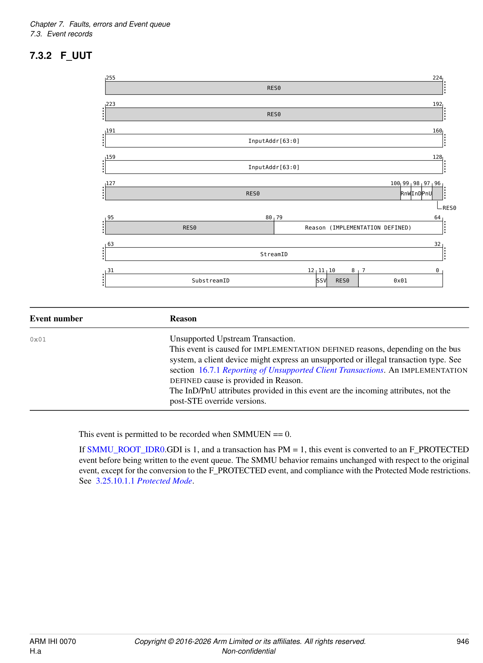
| Event number | Reason |
|---|---|
| 0x0B | An external abort occurred fetching (or updating) a translation table descriptor (access |
| aborted by system/interconnect/Completer, or consumed external error where RAS features | |
| available). | |
| The InD/PnU attributes are the post-STE override values. RnW pertains to the input | |
| transaction (InputAddr), not the access causing the abort. InD == 0 when RnW == 0 (see | |
| section 13.1.2_Attribute support_). | |
| A stage 1-only table walk that encounters EABT on physical access to a descriptor is | |
| reported as S2 == 0 (stage 1), CLASS == TT. The SMMU input transaction address | |
| (InputAddr) and descriptor fetch PA (FetchAddr) are provided. | |
| Note: This behavior of CLASS == TT when S2 == 0 differs from other | |
| F_TRANSLATION, F_ADDR_SIZE, F_ACCESS, F_PERMISSION events relating to a | |
| stage 1 fault. | |
| A stage 2 table walk can encounter EABT accessing the physical address of a stage 2 | |
| descriptor, because of a: | |
| • Translation of an IPA for CD fetch | |
| – S2 == 1 (stage 2), CLASS == CD | |
| – The SMMU input address (InputAddr) and S2 descriptor fetch PA (FetchAddr) | |
| are provided | |
| • Translation of an IPA for Stage 1 descriptor fetch | |
| – S2 == 1 (stage 2), CLASS == TT | |
| – The SMMU input address (InputAddr) and S2 descriptor fetch PA (FetchAddr) | |
| are provided | |
| • Translation of an IPA after successful stage 1 translation (or, in stage 2-only | |
| confguration, an input IPA) | |
| – S2 == 1 (stage 2), CLASS == IN (Input to stage) | |
| – The SMMU input address (InputAddr) and S2 descriptor fetch PA (FetchAddr) | |
| are provided. | |
| In a nested confguration, a stage 1 walk can encounter EABT accessing the physical | |
| address of a stage 1 descriptors having successfully translated the IPA of the descriptor to a | |
| PA through stage 2: | |
| • S2 == 0 (stage 1), CLASS == TT | |
| • This is equivalent to the stage 1-only case. | |
| • The SMMU input address (InputAddr) and S1 descriptor fetch PA (FetchAddr) are | |
| provided. | |
| An IMPLEMENTATION DEFINEDcause is provided in Reason. | |
| Note: This event occurs because of an incorrect confguration or, for systems supporting | |
| RAS features, consumption of an external error. A stage 1-only translation failing to walk a | |
| translation table might result from use of an incorrect or out of range PA in the table. When | |
| virtualization is in use, stage 2 translations would normally be fetched correctly. In | |
| addition, Arm recommends that hypervisor software does not allow a stage 1 walk to fetch | |
| a descriptor from an IPA that successfully translates to PA that causes an abort on access. | |
| When a VMSAv8-32 LPAE translation table descriptor fetch leads to an F_WALK_EABT | |
| on a system that has OAS < 40, a 40-bit descriptor address was truncated to the OAS to | |
| make the fetch. In this case,bits FetchAddr[47:OAS]are UNKNOWN. |
Note: To create the illusion of a guest VM having a stage 1-only virtual SMMU, this event can be injected into the guest if a stage 2 Translation, Access flag, Permission or Address Size fault occurs because of an access made by a stage 1 translation table walk (CLASS == TT).
InputAddr[11:0] are IGNORED for the purposes of determining identical events for merging.
FetchAddr bits [55:OAS] are RES0 if OAS is smaller than 56, where OAS is the system physical address size reported by SMMU_IDR5.OAS.
If SMMU_ROOT_IDR0.GDI is 1, and a transaction has PM = 1, this event is converted to an F_PROTECTED event before being written to the event queue. The SMMU behavior remains unchanged with respect to the original event, except for the conversion to the F_PROTECTED event, and compliance with the Protected Mode restrictions. See 3.25.10.1.1 Protected Mode .
7.3.13 F_TRANSLATION
255 248 247 224
RES0 IPA[55:12]
223 204 203 192
IPA[55:12] RES0
191 160
InputAddr[63:0]
159 128
InputAddr[63:0]
127 112 111 106 105 104 103 102 101 100 99 98 97 96
IMPL_DEF RES0 CLASS S2 RES0 RnWInDPnU
NSIPA RES0
95 94 80 79 64
RES0 STAG
Stall
63 32
StreamID
31 12 11 10 8 7 0
SubstreamID SSV RES0 0x10
Event number
Reason
0x10 Translation fault: The address provided to a stage of translation failed the range check defined by TxSZ/SLx, the address was within a disabled TTBx, or a valid translation table descriptor was not found for the address.
The RnW, InD and PnU fields provide the access attributes of the input transaction. The InD/PnU attributes are the post-STE override values. InD == 0 when RnW == 0. If fault occurs at stage 1, S2 == 0 and:
-
CLASS == IN, IPA is UNKNOWN.
-
If fault occurs at stage 2, S2 == 1 and: • If fetching a CD, CLASS == CD, IPA is CD address
-
If walking stage 1 translation table, CLASS == TT, IPA is the stage 1 translation table descriptor address
-
If translating an IPA for a transaction (whether by input to stage 2-only configuration, or after successful stage 1 translation), CLASS == IN, and IPA is provided.
-
If Stall == 1, not merged. InputAddr[11:0] are IGNORED for the purposes of determining identical events for merging.
IPA bits [55:OAS] are RES0 if OAS is smaller than 56, where OAS is the system physical address size reported by SMMU_IDR5.OAS.
If SMMU_R_IDR3.MEC == 1 then F_TRANSLATION can be generated as a result of the AMEC bit in some situations. See Chapter 18 Support for Memory Encryption Contexts .
If SMMU_ROOT_IDR0.GDI is 1, and a transaction has PM = 1, this event is converted to an F_PROTECTED event before being written to the event queue. The SMMU behavior remains unchanged with respect to the original event, except for the conversion to the F_PROTECTED event, and compliance with the Protected Mode restrictions. See 3.25.10.1.1 Protected Mode .
7.3.14 F_ADDR_SIZE
255 248 247 224
RES0 IPA[55:12]
223 204 203 192
IPA[55:12] RES0
191 160
InputAddr[63:0]
159 128
InputAddr[63:0]
127 112 111 106 105 104 103 102 101 100 99 98 97 96
IMPL_DEF RES0 CLASS S2 RES0 RnWInDPnU
NSIPA RES0
95 94 80 79 64
RES0 STAG
Stall
63 32
StreamID
31 12 11 10 8 7 0
SubstreamID SSV RES0 0x11
| Event number | Reason |
|---|---|
| 0x11 | Address Size fault: Output address of a translation stage caused Address Size fault. When |
| the stage performs translation, this fault occurs when an intermediate or leaf translation | |
| table descriptor outputs an address outside of the effective xPS associated with the | |
| translation table (seeCD.IPSandSTE.S2PS). This does not include a TTB address out of | |
| range before the TTW begins as, in this condition, the CD or STE is invalid which results in | |
| C_BAD_CD or C_BAD_STE. When stage 1 bypasses translation, this fault occurs when | |
| the output address (identical to the input address) is outside the address range implemented, | |
| see section 3.4_Address sizes_. | |
| Refer to F_TRANSLATION for the defnition of the CLASS, IPA and S2 felds. | |
| The RnW, InD and PnU felds provide the access attributes of the input transaction. The | |
| InD/PnU attributes are the post-STE override values. InD == 0 when RnW == 0. | |
| If caused by stage 1 translation bypass (because of stage 1 being disabled, unimplemented, | |
| or bypassed whenSTE.S1DSS== 0b01), CLASS == IN and S2 == 0 (stage 2 bypass does | |
| not cause this fault). |
If Stall == 1, not merged. InputAddr[11:0] are IGNORED for the purposes of determining identical events for merging.
IPA bits [55:OAS] are RES0 if OAS is smaller than 56, where OAS is the system physical address size reported by SMMU_IDR5.OAS.
If SMMU_ROOT_IDR0.GDI is 1, and a transaction has PM = 1, this event is converted to an F_PROTECTED
event before being written to the event queue. The SMMU behavior remains unchanged with respect to the original event, except for the conversion to the F_PROTECTED event, and compliance with the Protected Mode restrictions. See 3.25.10.1.1 Protected Mode .
7.3.15 F_ACCESS
255 248 247 224
RES0 IPA[55:12]
223 204 203 192
IPA[55:12] RES0
191 160
InputAddr[63:0]
159 128
InputAddr[63:0]
127 112 111 106 105 104 103 102 101 100 99 98 97 96
IMPL_DEF RES0 CLASS S2 RES0 RnWInDPnU
NSIPA RES0
95 94 80 79 64
RES0 STAG
Stall
63 32
StreamID
31 12 11 10 8 7 0
SubstreamID SSV RES0 0x12
Event number
Reason
0x12
Access flag fault due to AF == 0 in a Page or Block descriptor.
If HTTU is supported and enabled, a descriptor with AF == 0 is modified such that AF == 1 and this fault is not recorded.
Refer to F_TRANSLATION for the definition of the CLASS, IPA and S2 fields. The RnW, InD and PnU fields provide the access attributes of the input transaction. The InD/PnU attributes are the post-STE override values. InD == 0 when RnW == 0.
If Stall == 1, not merged. InputAddr[11:0] are IGNORED for the purposes of determining identical events for merging.
IPA bits [55:OAS] are RES0 if OAS is smaller than 56, where OAS is the system physical address size reported by SMMU_IDR5.OAS.
If SMMU_ROOT_IDR0.GDI is 1, and a transaction has PM = 1, this event is converted to an F_PROTECTED event before being written to the event queue. The SMMU behavior remains unchanged with respect to the original event, except for the conversion to the F_PROTECTED event, and compliance with the Protected Mode restrictions. See 3.25.10.1.1 Protected Mode .
7.3.16 F_PERMISSION
255 248 247 224
RES0 IPA[55:12]
223 204 203 192
IPA[55:12] RES0
191 160
InputAddr[63:0]
159 128
InputAddr[63:0]
127 112 111 110 109 108 107 106 105 104 103 102 101 100 99 98 97 96
IMPL_DEF XT CLASS S2 RES0 RnWInDPnU
RES0 NSIPA RES0
Overlay DirtyBit
TTRnW AssuredOnly
95 94 80 79 64
RES0 STAG
Stall
63 32
StreamID
31 12 11 10 8 7 0
SubstreamID SSV RES0 0x13
Event number Reason
0x13
Permission fault occurred on page access. S2 indicates the stage at which fault occurred. The RnW, InD and PnU fields provide the access attributes of the input transaction. The InD/PnU attributes are the post-STE override values. InD == 0 when RnW == 0. Refer to F_TRANSLATION for the definition of the CLASS, IPA and S2 fields. The TTRnW field is valid when CLASS == TT, that is, a stage 1 translation table walk causes a Permission fault at stage 2. TTRnW is UNKNOWN when CLASS is not TT. TTRnW indicates the read/write property that actually caused the fault as follows:
0 Translation table descriptor Write caused S2 Permission fault. 1 Translation table descriptor Read caused S2 Permission fault. Note: For example, an input read might end up causing a translation table walk write permissions fault at stage 2, when HTTU updates a stage 1 Access flag. Note: When CLASS == TT, the IPA field indicates the stage 1 translation table entry address.
Note: Software is expected to use the CLASS field in order to determine the access properties causing the Permission fault. When CLASS == IN, RnW/InD/PnU were inappropriate for the access at the faulting stage. When CLASS == TT, the access is implicitly Data (regardless of the input property) and the faulting R/W property is given by TTRnW. When CLASS == CD, the access is implicitly Data and a read.
If Stall == 1, not merged. InputAddr[11:0] are IGNORED for the purposes of determining identical events for merging.
In SMMUv3.0, IPA bits [51:48] are RES0.
In an SMMU with RME DA, a translation results in F_PERMISSION in the following scenarios:
-
If the stage 2 translation for the fetch of a Realm L1CD or CD results in a Non-secure address, that results in F_PERMISSION at stage 2.
-
Consistent with FEAT_RME [2], if the stage 2 translation for a stage 1 translation table walk resolves to a Non-secure address, that results in F_PERMISSION at stage 2.
-
Consistent with FEAT_RME [2], any Realm instruction fetch that resolves to an Non-secure address results in F_PERMISSION at the stage that configured the Non-secure output address.
If SMMU_IDR3.S2PO is 1, then the Overlay bit is set to 1 for stage 2 Permission faults generated as a result of the stage 2 Overlay permission preventing the access. Otherwise, Overlay is reported as 0.
If SMMU_IDR3.S2PI is 1, then the AssuredOnly bit is set to 1 for stage 2 Permission faults generated only because of the AssuredOnly check. Otherwise, AssuredOnly is 0.
If SMMU_R_IDR3.XT is 1, then the XT bit is set to 1 for Permission faults generated as a result of the XT checks, as specified in the table in 3.9.4.3 XT bit on Untranslated transactions, Translation requests and Translated transactions . Otherwise, XT is reported as 0.
If either SMMU_IDR3.S2PI or SMMU_IDR3.S1PI is 1, then the DirtyBit is set to 1 for Permission faults generated from a stage of translation using the Indirect Permission Scheme that has hardware updates of dirty state disabled, and if hardware update of dirty state were enabled the access that caused the fault would have caused an update to the dirty state. Otherwise, DirtyBit is 0.
If SMMU_ROOT_IDR0.GDI is 1, and a transaction has PM = 1, this event is converted to an F_PROTECTED event before being written to the event queue. The SMMU behavior remains unchanged with respect to the original event, except for the conversion to the F_PROTECTED event, and compliance with the Protected Mode restrictions. See 3.25.10.1.1 Protected Mode .
7.3.17 F_TLB_CONFLICT
255 248 247 224
RES0 IPA[55:12]
223 204 203 192
IPA[55:12] RES0
191 160
InputAddr[63:0]
159 128
InputAddr[63:0]
127 104 103 102 101 100 99 98 97 96
RES0 S2 RES0 RnWInDPnU
NSIPA RES0
95 64
Reason (IMPLEMENTATION DEFINED)
63 32
StreamID
31 12 11 10 8 7 0
SubstreamID SSV RES0 0x20
| Event number | Reason |
|---|---|
| 0x20 | A TLB confict occurred because of the transaction. The nature of this is IMPLEMENTATION |
| DEFINED, defned by the TLB geometry of the implementation. The input address might not | |
| be the address that causes the issue, for example an IPA to PA TLB entry might experience | |
| the problem, so both addresses are provided. | |
| The RnW, InD and PnU felds provide the access attributes of the input transaction. The | |
| InD/PnU attributes are the post-STE override values. InD == 0 when RnW == 0. | |
| An IMPLEMENTATION DEFINEDconfict reason is provided in Reason. This information | |
| might be specifc to the TLB geometry of the implementation. | |
| IPA is valid when S2 == 1, otherwise it is UNKNOWN. |
InputAddr[11:0] are IGNORED for the purposes of determining identical events for merging.
IPA bits [55:OAS] are RES0 if OAS is smaller than 56, where OAS is the system physical address size reported by SMMU_IDR5.OAS.
If SMMU_ROOT_IDR0.GDI is 1, and a transaction has PM = 1, this event is converted to an F_PROTECTED event before being written to the event queue. The SMMU behavior remains unchanged with respect to the original event, except for the conversion to the F_PROTECTED event, and compliance with the Protected Mode restrictions. See 3.25.10.1.1 Protected Mode .
7.3.18 F_CFG_CONFLICT
| 255 224 | 255 224 | 255 224 | 255 224 |
|---|---|---|---|
| RES0 | |||
| 223 192 | |||
| RES0 | |||
| 191 160 | |||
| RES0 | |||
| 159 128 | |||
| RES0 | |||
| 127 96 | |||
| RES0 | |||
| 95 64 | |||
| Reason (IMPLEMENTATION DEFINED) | |||
| 63 32 | |||
| StreamID | |||
| 31 12 11 10 8 7 0 | |||
| SubstreamID | SSV | RES0 | 0x21 |
| Event number | Reason |
|---|---|
| 0x21 | A confguration cache confict occurred due to the transaction. The nature of this is |
| IMPLEMENTATION DEFINED, defned by the confguration cache geometry of the | |
| implementation. | |
| TheSTE.CONTproperty of an STE cache entry causes an overlap of another STE that is | |
| not identical , as described inSTE.CONT, and this has caused a multiple-match on lookup. | |
| An IMPLEMENTATION DEFINEDconfict reason is provided in Reason. This information | |
| might be specifc to the confguration cache geometry of the implementation. |
It is not possible to cause this error by any CD misconfiguration.
Note: A guest VM cannot arrange configuration that would affect any other streams.
7.3.19 E_PAGE_REQUEST
255 224
RES0
223 192
RES0
191 160
InputAddr[63:12]
159 140 139 128
InputAddr[63:12] RES0
127 116 115 108 107 104 103 102 101 100 99 98 97 96
RES0 Span RES0 pR pW pX uR uW uX
RES0 RES0
95 64
RES0
63 32
StreamID
31 12 11 10 8 7 0
SubstreamID SSV RES0 0x24
Event number Reason
0x24 Speculative page request hint from a client device to system software, hinting that the given
address span will be accessed by a device in the near future. The access is expected to
require the read/write/execute properties provided for user/kernel privilege levels.
No response or action is required, but system software might use this hint to begin a (potentially long-running) page-in of the given address, to decrease the chance of a subsequent access from the device experiencing a page miss.
| Flag felds | Access anticipated |
|---|---|
| pR | Privileged Read |
| pW | Privileged Write |
| pX | Privileged Execute |
| uR | Unprivileged Read |
| uW | Unprivileged Write |
| uX | Unprivileged Execute |
Span is encoded as a positive integer where the size of the intended access span in bytes is (Span*4096).
If SMMU_ROOT_IDR0.GDI is 1, and a transaction has PM = 1, this event is converted to an F_PROTECTED event before being written to the event queue. The SMMU behavior remains unchanged with respect to the original event, except for the conversion to the F_PROTECTED event record and compliance with the Protected Mode restrictions. See 3.25.10.1.1 Protected Mode .
7.3.20 F_VMS_FETCH
255 248 247 224
RES0 FetchAddr[55:3]
223 195 194 192
FetchAddr[55:3] RES0
191 160
RES0
159 128
RES0
127 96
RES0
95 81 80 79 64
RES0 Reason (IMPLEMENTATION DEFINED)
GPCF
63 32
StreamID
31 12 11 10 8 7 0
SubstreamID SSV RES0 0x25
Event number
Reason
0x25
Fetch of VMS caused external abort (access aborted by system/interconnect/Completer, or consumed external error where RAS features available). FetchAddr is the Physical Address used for the fetch. In SMMUv3.0, bits [47:OAS] are UNKNOWN. In SMMUv3.1 and later, bits [51:OAS] are UNKNOWN. An IMPLEMENTATION DEFINED cause is provided in Reason.
The F_VMS_FETCH event has a lower priority than the C_BAD_STE event. The priority with respect to
subsequent possible events is IMPLEMENTATION DEFINED. See sections 7.3.23 Event queue record priorities and 9.1.5 *ATOS_PAR.FAULTCODE encodings .
Note: If a F_VMS_FETCH event is reported, a C_BAD_STE has not been reported because a valid STE is required to fetch the VMS. The point at which the VMS is fetched relative to the remainder of the configuration structure walk and translation process is not specified.
FetchAddr bits [55:OAS] are RES0 if OAS is smaller than 56, where OAS is the system physical address size reported by SMMU_IDR5.OAS.
7.3.21 F_PROTECTED
| 255 224 | 255 224 | 255 224 | 255 224 |
|---|---|---|---|
| RES0 | |||
| 223 192 | |||
| RES0 | |||
| 191 160 | |||
| RES0 | |||
| 159 128 | |||
| RES0 | |||
| 127 96 | |||
| RES0 | |||
| 95 64 | |||
| RES0 | |||
| 63 32 | |||
| StreamID | |||
| 31 12 11 10 8 7 0 | |||
| SubstreamID | SSV | RES0 | 0x26 |
Event number
Reason
0x26
A transaction with PM = 1 generated one of the following events:
-
F_UTT.
-
F_BAD_ATS_TREQ.
-
F_TRANSL_FORBIDDEN.
-
F_WALK_EABT.
-
F_TRANSLATION.
-
F_ADDR_SIZE.
-
F_ACCESS.
-
F_PERMISSION.
-
F_TLB_CONFLICT.
-
E_PAGE_REQUEST.
The SMMU behavior is unchanged with respect to the original event, other than converting it to the F_PROTECTED event record and conforming to the behaviors specificed in section 3.25.10.1.1 Protected Mode .
7.3.22 IMPDEF_EVENTn
| Event number | Reason |
|---|---|
| 0xE0-0xEF | IMPLEMENTATION DEFINEDevent allocation. |
Notes: Arm recommends that software treats receipt of these events as a non-fatal occurrence even if the exact nature of the event is not recognized.
All other event numbers are Reserved.
Events with a Stall parameter (F_TRANSLATION, F_ADDR_SIZE, F_ACCESS, F_PERMISSION) indicate whether a transaction is stalling as a result of the event. When a transaction causes any other event, the transaction is terminated and an abort returned to the client. If a transaction is stalled, the STAG parameter provides a token used to uniquely identify the transaction.
Note: The StreamID and STAG must be provided to a subsequent CMD_RESUME. Every stall event must have either one associated CMD_RESUME or a CMD_STALL_TERM.
A configuration error always terminates the instigating transaction with an abort to the device.
Multiple addresses might be reported in one event record:
-
InputAddr is the address input with the transaction to the SMMU.
-
IPA is the post-stage 1 address of the transaction, valid only if the fault occurred at stage 2.
-
Fetch PA is the physical address accessed causing the fault to be raised.
The input address is the 64-bit address presented to the SMMU, see section 3.4.1 Input address size and Virtual Address size .
7.3.23 Event queue record priorities
Events arising from an ordinary incoming transaction are recorded in the following order, listed from the first that might occur when a transaction is processed to the last that might occur before the transaction is deemed successful, unless otherwise specified. This means that if any event occurs, events prior to that event in this list cannot have occurred:
-
C_BAD_STREAMID
-
F_STE_FETCH
-
C_BAD_STE
-
F_VMS_FETCH
F_VMS_FETCH is only lower priority than C_BAD_STE. Its priority relative to other lower priority events in this list is IMPLEMENTATION DEFINED.
-
C_BAD_SUBSTREAMID
-
F_STREAM_DISABLED
-
Faults from translation (stage 2, for fetch of CD)
-
F_CD_FETCH
-
C_BAD_CD
-
Faults from translation (stage 1 or stage 2, for data access of a transaction)
Faults from translation can occur because of a fetch of a CD or stage 1 translation requiring a stage 2 translation, or the final translation for the given transaction address.
A single stage of translation table walk might experience faults in this order:
-
F_TRANSLATION (for input address outside range defined by TxSZ/SL0, or EPDx == 1)
-
For each level of translation table walked:
-
a. F_WALK_EABT (on fetch of descriptor)
-
b. F_TRANSLATION (from fetched descriptor)
-
c. F_ADDR_SIZE (for output of descriptor, indicating next descriptor or walk output address)
-
-
F_ACCESS (On the final-level descriptor)
-
F_PERMISSION (On the final-level descriptor)
- A nested Stage 1 + Stage 2 translation table walk might experience faults in this order:
-
F_TRANSLATION (For stage 1 input address outside range defined by stage 1 TxSZ/SL0, or EPDx == 1)
-
For each level of stage 1 translation table walked, the stage 2 translation for the descriptor of the stage 1s IPA might experience:
-
a. F_TRANSLATION (For stage 2 input address outside range defined by stage 2 T0SZ/SL0)
-
b. F_WALK_EABT (For stage 2 descriptor fetch)
-
c. F_TRANSLATION (From fetched stage 2 descriptor)
-
d. F_ADDR_SIZE (For output of stage 2 descriptor, indicating next descriptor or walk output address)
-
e. F_ACCESS (On the final-level stage 2 descriptor)
-
f. F_PERMISSION (On the final-level stage 2 descriptor)
-
-
For each level of stage 1 translation table walked, after the PA of the descriptor is determined the following might occur:
-
a. F_WALK_EABT (For stage 1 descriptor fetch)
-
b. F_TRANSLATION (From fetched stage 1 descriptor)
-
c. F_ADDR_SIZE (For output of stage 1 descriptor)
-
-
For the final level stage 1 descriptor, the following might then occur:
-
a. F_ACCESS
-
b. F_PERMISSION
-
-
The IPA relating to the input VA has been determined and permissions have been checked, but the following might occur for each level of the stage 2 translation of that final IPA:
-
a. F_TRANSLATION (For stage 2 input address outside range defined by stage 2 T0SZ/SL0) b. F_WALK_EABT (For stage 2 descriptor fetch)
-
c. F_TRANSLATION (From fetched stage 2 descriptor)
-
d. F_ADDR_SIZE (For output of stage 2 descriptor, indicating next descriptor or walk output address)
-
e. F_ACCESS (On the final-level stage 2 descriptor)
-
f. F_PERMISSION (On the final-level stage 2 descriptor)
-
Note: F_TLB_CONFLICT, F_CFG_CONFLICT and F_UUT are raised with IMPLEMENTATION SPECIFIC prioritization.
Note: Converting an event to F_PROTECTED occurs after priority has been resolved for the original event.
For an SMMU with RME, then each of F_STE_FETCH, F_CD_FETCH, F_VMS_FETCH and F_WALK_EABT can also occur as the result of a granule protection check fault. This does not affect the error reporting priority described in this section. See also section 3.25.3 SMMU-originated accesses .
The flow of events that an incoming ordinary transaction might raise can be characterized as:
-
An unsupported transaction fault from the client device might be raised on input.
-
Configuration is fetched, in the order of STE then (if relevant) CD:
-
If a CD is fetched, it uses stage 2 translations to do so, if stage 2 is enabled.
-
Stage 2 walk occurs, which might experience an external abort on fetch.
-
Stage 2 page fault on the CD address might occur when the walk completes.
-
External abort on CD fetch might occur.
-
-
When a CD is successfully fetched, start walking stage 1 TT. Stage 2 page faults (or external aborts) might arise from walking stage 1, in the same way as for the initial CD fetch
-
When a S1 translation is determined, stage 1 might fault.
-
Stage 2 walk occurs for a successful output of stage 1 translation, and this might also fault.
ATS Translation Requests do not lead to the same set of possible errors as, in general, ATS translation errors are reported to the requesting device using the ATS Translation Completion rather than to software through the Event queue. The only Event queue record that can be generated is F_BAD_ATS_TREQ, which can be raised at several points in the translation process.
ATS Translated transactions also differ from ordinary transactions and one of the following behaviors can occur:
-
F_TRANSL_FORBIDDEN can be raised on input when ATS is disabled/invalid. See section 7.3.8 F_TRANSL_FORBIDDEN .
-
If SMMU_(R_)CR0.SMMUEN == 1, SMMU_(R_)CR0.ATSCHK == 1 and SMMU_(R_)CR2.REC_CFG_ATS == 1, then if the SMMU encounters an error when fetching a configuration structure, the appropriate event is recorded. See section 3.9.1.3 Handling of ATS Translated transactions .
-
An ATS Translated transaction that locates the correct configuration and then encounters stage 2 translation (through STE.EATS == 0b10 configuration) can raise stage 2 Translation-related faults.
-
Otherwise, any other error on receipt of an ATS Translated transaction (for example, an invalid STE) causes the transaction to be silently terminated.
See Chapter 15 Translation procedure for more details on the translation procedure and possible events at each step.
7.4 Event queue overflow
An SMMU output queue is full if the consumer can observe that there are no free entries for the producer to add new entries to, see section 3.5.2 Queue entry visibility semantics . The Event queue is full if it can be observed that SMMU_()EVENTQ_PROD.WR == SMMU(_)EVENTQ_CONS.RD and WRAP bits differ.
Note: If the SMMU can observe that a write it made for a new queue entry is visible in memory, but PROD.WR has not yet been updated to pass the position of the new entry, the new entry is not yet visible to software in terms of the queue visibility semantics.
Event queue overflow occurs when the Event queue is enabled (EVENTQEN == 1), the queue is full, and a pending event record is discarded because the queue is full. An Event queue overflow condition is entered to indicate that one or more event records have been lost:
-
Fault information.
-
Configuration errors.
It is not possible for an external agent to observe an Event queue overflow condition if it could not first observe the Event queue being full.
Note: An implementation must therefore prevent the overflow condition from being observable by software before an update to the PROD index is observable.
A configuration error record or fault record from a terminated transaction is discarded when the SMMU attempts to insert it into a full Event queue. However, a fault record from a stalled transaction is not discarded and an event is reported for the stalled transaction when the queue is next writable. In addition, as stall fault records are not discarded, stall fault records do not cause an overflow condition. Only discarded events cause overflow.
When EVENTQEN == 0, events are not delivered and non-stall event records might be discarded but do not cause an overflow condition.
The Event queue overflow condition is present when:
SMMU_EVENTQ_PROD.OVFLG != SMMU_EVENTQ_CONS.OVACKFLG
When an overflow occurs, the SMMU toggles the SMMU_EVENTQ_PROD.OVFLG flag if the overflow condition is not already present.
Note: Arm recommends that whenever software reads SMMU_EVENTQ_PROD, it checks OVFLG against its own copy. If different, the overflow condition arose. Arm recommends that software then updates its copy with the value of OVFLG, and processes the Event queue entries as quickly as possible, updating SMMU_EVENTQ_CONS in order to move on the RD pointer but also to acknowledge receipt of the overflow condition by setting OVACKFLG to the same value read from OVFLG.
Note: In terms of delivering events, a queue in an unacknowledged overflow state does not behave any differently to normal queue state. If software were to consume events and free space but leave overflow unacknowledged, new events could be recorded. Because a second overflow condition cannot be indicated, a subsequent queue overflow would be invisible therefore Arm expects software to acknowledge overflow upon the first consumption of events after the condition arose.
7.5 Global error recording
Global Errors pertaining to a programming interface are reported into the appropriate SMMU_(*_)GERROR register instead of into the memory-based Event queue.
SMMU_(*_)GERROR provides a one-bit flag for each of the following error conditions:
| Error fag | Meaning |
|---|---|
| CMDQ_ERR | Command queue error |
| EVENTQ_ABT_ERR | Event queue access aborted |
| Delivery into the Event queue stops when an abort is fagged, see section 7.2_Event queue_ | |
| recorded faults and events. | |
| PRIQ_ABT_ERR | PRI queue access aborted |
| Delivery into the PRI queue stops when an abort is fagged, see section 8.2_Miscellaneous_. | |
| MSI_CMDQ_ABT_ERR | CMD_SYNCMSI write aborted |
| MSI_EVENTQ_ABT_ERR | Event queue MSI write aborted |
| MSI_PRIQ_ABT_ERR | PRI queue MSI write aborted (Non-secure GERROR only) |
| MSI_GERROR_ABT_ERR | GERROR MSI write aborted |
| SFM_ERR | SMMU entered Service Failure Mode |
| This error is common to bothSMMU_GERRORandSMMU_S_GERROR, so that both Secure | |
| and Non-secure software are aware that the SMMU has entered SFM. | |
| CMDQP_ERR | Command queue control page error |
| This error signals that there was an error while fetching or processing a command related to an | |
| ECMDQ instance. The presence of the error is also indicated in | |
| SMMU_(*_)ECMDQ_CONSn.ERR and the reason for the error is available in | |
| SMMU_(*)ECMDQ_CONSn.ERR_REASON. See section 3.5.6.3_Errors relating to an | |
| ECMDQ interface. | |
| DPT_ERR | DPT Lookup fault |
| This error indicates that one or more DPT lookup faults have occurred. The syndrome | |
| information is available inSMMU_(R_)DPT_CFG_FAR. See section 3.24.4_DPT lookup_ | |
| errors. | |
| If this error is reported due to PM = 1, thenSMMU_DPT_CFG_FAR.FADDR is set to 0. See | |
| section 3.25.10.1.1_Protected Mode_. | |
| HDBSS_ERR | HDBSS update error |
| See section 3.13.9_Hardware Dirty state tracking Structure_. | |
| MSI_HDBSS_ABT_ERR | HDBSS table full MSI aborted |
| See section 3.13.9_Hardware Dirty state tracking Structure_. | |
| HACDBS_ERR | HACDBS error |
| See section 3.13.10_Hardware Accelerator for Cleaning Dirty State_. | |
| MSI_HACDBS_ABT_ERR | HACDBS processing complete MSI aborted |
| See section 3.13.10_Hardware Accelerator for Cleaning Dirty State_. | |
| DCMDQP_ERR | Error on a DCMDQ control page. |
| See section3.5.7_Direct-mode Enhanced Command Queues_. |
When an error condition is triggered, the error is activated by toggling the corresponding flag in GERROR. In some cases, SMMU behavior changes while the error is active:
- Commands are not consumed from the Command queue while CMDQ_ERR is active.
The presence of a Global Error is acknowledged by the agent controlling the SMMU by toggling the equivalent field in the GERRORN register.
An error is active when: SMMU_()GERROR[x] != SMMU(_)GERRORN[x]
The SMMU does not toggle bit[x] if the error is already active. If one or more new errors occur while a previous error of the same type is active, the new error is not logged.
Note: This handshake avoids a race condition that could otherwise lead to loss of error events. It follows that an error flag indicates that one or more of the indicated errors has occurred since the last acknowledgment.
It is IMPLEMENTATION DEFINED whether the interconnect to the memory system of an implementation returns abort completions for writes, which lead to *_ABT_ERR global errors.
Note: A GPC fault can also result in reporting of *_ABT_ERR global errors. See 3.25.5 SMMU behavior if a GPC fault is active for details on how other aspects of the GPC fault are reported.
7.5.1 GERROR interrupt notification
A GERROR interrupt is triggered when the SMMU activates an error, with the exception of the following fields:
-
MSI_GERROR_ABT_ERR
- Note: This error signifies that a prior attempt to raise a GERROR MSI had been aborted, and sending another to the same address might cause a second abort.
The GERROR interrupt is triggered only when SMMU_()IRQ_CTRL.GERROR_IRQEN == 1. When MSIs are used, GERROR MSI notification is configured using SMMU(_)GERROR_IRQ_CFG{0,1,2}. If multiple errors activate at the same time, GERROR interrupts are permitted to be coalesced.
Where the architecture guarantees that a GERROR flag update is visible before the completion of an action that might have triggered an error, completion of such an action is not required to depend on the GERROR interrupt having been made visible.
Note: For example, an IRQ enable update from 1 to 0 does not complete until the abort of a prior MSI is recorded as GERROR.MSI_*_ABT_ERR, but the update is permitted to complete before the GERROR interrupt is triggered.
Page request queue
Chapter 8 Page request queue
The message format arriving on the PRI queue in response to an incoming PCIe PRI message closely follows the PCIe packet format. The field names have been generalized for consistency with terminology elsewhere in this specification. PRI messages are little-endian. The system must ensure that the mapping between StreamID and RequesterID or Root Complex is identical whether used in either incoming or outgoing directions for PRI, ATS or normal DMA traffic.
| 127 96 | 127 96 | 127 96 | 127 96 | 127 96 | 127 96 | 127 96 | 127 96 | 127 96 | 127 96 |
|---|---|---|---|---|---|---|---|---|---|
| Page Address [63:12] | |||||||||
| 95 76 75 73 72 64 | |||||||||
| Page Address [63:12] | RES0 | PRGIndex | |||||||
| 63 62 61 60 59 58 57 52 51 32 | |||||||||
| SSV | L | W | R | X | RES0 | SubstreamID | |||
| Priv 31 0 | |||||||||
| StreamID |
-
StreamID[31:0]
- When used with ATS/PRI, StreamID[15:0] must equal PCIe RequesterID[15:0]. Bits StreamID[n:16] might indicate different Root Complex sources where more than 16 bits of StreamID are implemented.
-
SSV: Substream valid
-
When 1, the Page Request was issued with a PASID TLP prefix.
-
When 0, the Page Request was not issued with a PASID. This value is also 0 when Substreams are not supported by the SMMU. When SSV == 0, the X and Priv bits are both 0.
-
-
SubstreamID[19:0]
- This value is UNKNOWN when SSV == 0.
-
Page address[63:12]
-
PRGIndex[8:0]
-
Last, W, R, X, Priv: Last/Write/Read/eXecute/Privileged:
-
These bits encode requested page permissions
-
‘Last’ is set on the last request in a PRG
-
The PCIe ‘Stop PASID’ marker message delimits Page Request message groups as a request with LWR == 0b100. Stop Markers have a PASID, that is, SSV == 1. A message that arrives without a PASID and that has LWR == 0b100 is not a Stop Marker, has SSV == 0, and is treated as a PRI Page Request.
-
Several related PRI Page Requests (PPRs) might arrive in batches, named Page Request Groups (PRGs). Several pages might be requested in a PRG and all arrive with the same PRGIndex value. The last page request in a PRG is marked by the Endpoint as Last == 1 and the PRI queue can be configured to send an interrupt when Last == 1 is received (see SMMU_PRIQ_IRQ_CFG2. Member requests of a PRG are not guaranteed to be contiguous in the PRI queue as requests of more than one PRG might be interleaved. PPRs that are members of the PRG are not guaranteed to appear in the PRI queue in the order that they were issued from an endpoint, with the exception of the Last == 1 entry which is not re-ordered with respect to prior PPRs.
The SMMU is not required to track and verify that, for a given PRGIndex value, all entries received in a PRG have identical PASID TLP prefixes.
The CMD_PRI_RESP command causes a PRI response to be sent to an endpoint and takes a success or failure parameter to inform the endpoint of the overall status of the PRG. When Substreams (PASIDs in this context) are supported and this command is used with a valid SubstreamID (SSV == 1), a PASID tag is present on the response.
Note: Arm expects this command to be issued after all PPRs in a PRG have been processed, including the Last == 1 entry.
Note: The PRI queue does not overflow with correct software usage and endpoint credit management, because software grants credits to each device (using PCI configuration space) which sum to the amount of space in the PRI queue minus an allowance for any ‘Stop PASID’ markers that are required. The device can only issue as many outstanding PPRs as it has credits for.
The SMMU freely accepts incoming PRI messages and puts them in the PRI queue, if space is free and the queue is enabled and not in an error condition. If the queue is full a programming error (or protocol failure by PCIe endpoint) has occurred.
Note: A device is intended to always receive a response to a PRG, whether positive or negative.
Note: A CMD_PRI_RESP returns a credit to the Endpoint that could cause another PPR. This must be considered when calculating credit capability of a queue. If the number of credits granted to devices equals the queue capacity, a PPR must be consumed from the queue (freeing an entry) prior to issuing a CMD_PRI_RESP for that PPR.
The SMMU supports a maximum PRI queue size of 2[19] entries.
Note: When a guest VM manages a PRI queue for page request service from one or more devices assigned to that guest, it is up to the guest OS to allocate and size its local PRI queue. It will subsequently give credits to the devices to allow them to issue PPRs, using configuration space accesses. In this scenario, the hypervisor manages the actual SMMU PRI queue and the sum of the credits given to all clients of that queue must not be greater than the size of the queue. For safety, Arm expects that a hypervisor will trap the write of a credit value of a guest to a device, and substitute its own allocation if necessary. This would ensure that the total number of credits cannot exceed the PRI queue size, even if a guest OS requests a larger number of credits to be used. The hypervisor is also expected to choose an appropriate PRI queue size which will approximate the sum of credits reasonably expected to be used by all guest VMs using the PRI facilities of an SMMU.
8.1 PRI queue overflow
The PRI queue enters an overflow condition when the following conditions apply:
-
The PRI queue is enabled, as indicated by the effective value of SMMU_CR0.PRIQEN == 1.
-
One or more PRI messages are received by the SMMU while the PRI queue is full, as determined by the general queue semantics.
The SMMU indicates that this has happened by toggling the SMMU_PRIQ_PROD.OVFLG flag, provided that an overflow condition is not already present. The overflow condition is acknowledged by writing the SMMU_PRIQ_CONS.OVACKFLG flag to the same value as OVFLG.
An active overflow condition inhibits new entries from being written to the PRI queue.
Note: This behavior differs from the active overflow condition on an Event queue. See also section 7.4 Event queue overflow .
Note: On detection of overflow, Arm recommends that software processes the received PRI queue entries as quickly as possible, and follows this with a single write of SMMU_PRIQ_CONS to simultaneously move on the RD pointer and acknowledge receipt of the overflow condition by setting OVACKFLG to the value read from OVFLG.
When an overflow condition is active, incoming PRI messages are discarded and:
- An automatic PRG Response is generated for Page Request messages having Last == 1, including the PRGI of the PPR that caused the overflow condition to become active. This response is returned to the endpoint that originated the PPR. The ResponseCode is defined below.
Note: This behavior occurs only for a Page Request message and does not occur when a Stop Marker is discarded in an overflow condition.
- PPRs having Last == 0 are silently ignored.
Note: The auto-response behavior can maintain safe operation when PCIe endpoints fail to fully adhere to the PRI credit mechanism.
Note: Although in an overflow condition the system software will not have addressed the cause of the PPR, on receipt of the automatic successful response Arm expects that the device will gracefully attempt an ATS request and PRI request again. On subsequent requests, system software might have had time to process the PRI queue contents and free space for the retries.
Note: Auto-responses might be sent because of an overflow condition, or for other reasons. See section 8.2 Miscellaneous .
When the SMMU supports PASIDs, an automatic PRG Response that is sent in response to a PRI queue overflow condition has the following properties:
-
If the associated Page Request message did not have a PASID, the response has no PASID and the ResponseCode field of the response is Success (0b0000). SMMU_IDR3.PPS and STE.PPAR do not affect this case.
-
If the associated Page Request message had a PASID:
-
If SMMU_IDR3.PPS == 1, then the response has the same PASID and the ResponseCode is Success (0b0000). STE.PPAR is not checked and its value is ignored.
-
If SMMU_IDR3.PPS == 0, the STE.PPAR field associated with the StreamID of the PPR is checked. The PASID depends on the associated STE:
-
[If the associated STE is valid, the response has the same PASID if][ STE.PPAR][ == 1 and it has no] PASID if STE.PPAR == 0. In both cases, ResponseCode is Success (0b0000).
-
[If the associated STE is inaccessible or invalid, such that][ STE.PPAR][ cannot be checked, no PASID] is used and the ResponseCode is Failure (0b1111). This occurs if SMMU_CR0.SMMUEN == 0, or
-
-
the StreamID is out of range of the Stream table, or an External Abort was encountered during the STE fetch or VMS fetch, or the STE is ILLEGAL.
Note: In SMMUv3.2 or later, an STE access is permitted to also access the VMS if the VMS is enabled, which means that VMS access is permitted to occur as part of an STE.PPAR check and that access might give rise to this response failure case.
If SMMU_CR2.RECINVSID == 1 and SMMU_CR2.REC_CFG_ATS == 1, and the SMMU encounters C_BAD_STREAMID while attempting to check STE.PPAR, the event is recorded in the Event queue. If SMMU_CR2.REC_CFG_ATS == 1, and the SMMU encounters F_STE_FETCH, F_VMS_FETCH, C_BAD_STE or F_CFG_CONFLICT while attempting to check STE.PPAR, the event is recorded in the Event queue. Otherwise, no event is recorded.
Note: For a normal transaction, the same conditions lead to C_BAD_STREAMID, F_STE_FETCH, and C_BAD_STE, respectively.
When PASIDs are not supported, an automatic response does not have a PASID prefix and the STE.PPAR field is not used. In this case, an implementation is permitted, but not required, to attempt to locate a valid STE and return either ResponseCode == Success or Failure in the manner described in this chapter even though STE.PPAR is not required. If the implementation does not perform this STE check, the ResponseCode == Success.
Note: A PRI-capable endpoint advertises whether it expects a PASID prefix to be present on a PRG response returned to it in response to a Page Request made with a PASID prefix, through the PRG Response PASID Required flag in the PRI Status register of the endpoint. Arm expects the STE.PPAR field associated with an endpoint to be programmed to the same value as this flag in the endpoint.
Stop PASID markers that arrive in an overflow condition are discarded and no auto-response is generated.
Note: The PCIe specification [1] does not consider PRI Stop PASID markers to be credited in the same way as PPRs. If endpoints disrespect Page Request allocation and credits, Stop PASID markers cannot be guaranteed to be visible to the system, given this rule. Software must use other means to determine PASID stop status in the presence of non-compliant PCIe endpoints.
8.1.1 Recovery procedure
At the time that an overflow is detected, the PRI queue might contain several groups of page requests that are legitimate, but might contain one or more groups of requests that have been truncated so that their ‘Last’ event was among those lost when overflow occurred, and these groups have had a ‘Success’ auto-response sent when the ‘Last’ event was discarded.
Note: To re-synchronize and regain normal processing of page requests, one possible method is:
-
Process the entire queue: Entries are read from the SMMU_PRIQ_CONS.RD index up to the SMMU_PRIQ_PROD.WR index, sending Page Request Group Response commands using the Command queue as appropriate, when ‘Last’ entries are encountered.
-
The PRI queue might contain the start of groups of page requests whose Last requests were lost, having been received and auto-responded to after overflow. A group must be ignored by software if no Last event has been found for it up to the point that the SMMU last wrote (the SMMU_PRIQ_PROD.WR index).
-
Update SMMU_PRIQ_CONS.RD, including OVACKFLG, to clear the overflow condition and mark the entire queue as empty or processed.
Note: After an overflow condition has been resolved, a PRGIndex value might be used in PPRs that later become visible, associated with a semantically different PRG to that of a PRG with entries in the pre-overflow PRI queue. This would occur when the queue enters overflow state before the Last PPR of the initial PRG can be recorded. The Last PPR has a successful auto-response sent, meaning the endpoint is free to re-use the PRGIndex value.
8.2 Miscellaneous
An external abort detected while accessing the PRI queue, for example when writing a record, activates the SMMU_GERROR.PRIQ_ABT_ERR Global Error. If PRIQ_ABT_ERR becomes active, one or more PRI records might have been lost. The behavior of PRIQ_ABT_ERR relates to entries written to the PRI queue as the behavior of EVENTQ_ABT_ERR relates to entries written to the Event queue, as described in section 7.2.2 Event queue access external abort . It is IMPLEMENTATION DEFINED whether an external abort that is triggered by a write to the PRI queue is synchronous or asynchronous. When the write of a PRI queue entry results in a synchronous external abort, an automatic PRG Response with ResponseCode == 0b1111 is generated for the associated PPR. When the write of a PRI queue entry results in an asynchronous external abort, one or more queue entries might have been lost and no automatic response is generated for the PPRs that are associated with these entries.
An implementation is permitted to read any address within the bounds of the PRI queue when the queue is enabled (that is, when the effective value of SMMU_CR0.PRIQEN == 1). In addition to writes of new records to the queue, such reads might also lead to an external abort.
A PPR received from a Secure stream is discarded, is not recorded into the PRI queue and results in an automatic Response Message having ResponseCode == 0b1111.
If an active GERROR.PRIQ_ABT_ERR error condition exists, or if the effective value of SMMU_CR0.PRIQEN == 0 (SMMU_CR0.SMMUEN == 0 implies PRIQEN == 0) all of the following apply:
-
No entries are written to the PRI queue.
-
All incoming PPRs cause an automatic PRG Response having ResponseCode == 0b1111 (‘Response Failure’) and the messages are discarded.
Note: Incoming PRI Page Requests are not affected by SMMU_CR0.ATSCHK or STE.EATS configuration.
The SMMU does not generate responses to Stop Marker messages.
Automatically-generated PRG responses have the following properties:
-
Same StreamID as the PPR that triggered the response so that the message is returned to the originating RequesterID.
-
Same Page Request Group Index as the PPR that triggered the response.
-
Response Code depends on the cause of auto-generated response, see this section and sections 8.1 PRI queue overflow and 8.3 PRG Response Message codes .
-
No PASID prefix is used on responses that were auto-generated because the effective value of PRIQEN == 0 or PRIQ_ABT_ERR occurred.
-
A PASID prefix is used if all of the following are true:
-
The response was auto-generated because of PRI queue overflow.
-
The SMMU supports substreams.
-
SMMU_IDR3.PPS == 1, or SMMU_IDR3.PPS == 0 and STE.PPAR == 1.
-
The response will not have ResponseCode == 0b1111.
-
The PPR that triggered the auto-response had a PASID prefix.
-
-
If a PASID prefix is used, its PASID value matches that of the PPR that triggered the response.
8.3 PRG Response Message codes
| ResponseCode | Status | Returned for |
|---|---|---|
| 0b0000 | Success | CMD_PRI_RESPwith Resp == Success |
| • Software has paged in all pages successfully. | ||
| This response is returned for an auto-response on overfow where no PASID | ||
| was supplied on the associated request, orSMMU_IDR3.PPS == 1, or no error | ||
| is encountered in checkingSTE.PPAR. | ||
| 0b0001 | Invalid | CMD_PRI_RESPwith Resp == InvalidRequest |
| Request | • Software failed to page-in all pages. It encountered one or more pages | |
| that do not exist or have insuffcient privileges | ||
| 0b1111 | Response | CMD_PRI_RESPwith Resp == ResponseFailure |
| Failure | • Software has determined that ATS is disabled for the stream, or some | |
| other (non-mapping-related) permanent failure. | ||
| This response is returned for an auto-response on overfow where | ||
| SMMU_IDR3.PPS == 0 and the associated request was supplied with a PASID | ||
| and the SMMU is unable to locate a valid STE when checkingSTE.PPAR. | ||
| This response is also returned for all incoming PPRs when any of the following | ||
| conditions exist: | ||
| • The effective value of PRIQEN == 0 (which might be because | ||
| SMMU_CR0.SMMUEN == 0), | ||
| • A GERROR.PRIQ_ABT_ERR error is active. | ||
| • The PPR is received from a Secure stream. |
Address Translation Operations
Chapter 9 Address Translation Operations
The SMMU optionally supports a software-accessible Address Translation Operations (ATOS) facility. The presence of this facility is reported by SMMU_IDR0.ATOS. The ATOS facility allows software to perform an address lookup to determine the output address that a transaction would take, given an input address, stream, substream and access properties. The requested lookup can be the full end-to-end, with all configured stages, or only a part of the configuration for the stream. The result of the request is either the output address or a fault status code, if a translation is unable to complete. Unlike transactions, ATOS requests are not affected by fault configuration bits in the STE or CD, and do not record fault events or stall.
If ATOS is supported, an optional virtual ATOS (VATOS) page might also be supported. This is reported by SMMU_IDR0.VATOS. The VATOS page can be mapped through to a chosen software entity so that it might perform a limited set of stage 1-only ATOS lookups directly. The VATOS interface can make stage 1-only ATOS lookups for stage 1 and stage 2 nested configurations, or for stage 1-only configurations. The VATOS interface can only make lookups for configurations associated with the NS-EL1 StreamWorld.
Note: Arm expects VATOS to be used with stage 1 and stage 2 nested configurations.
Note: Apart from differences in scope the groups of registers are equivalent and are referred to generically using *ATOS_ prefixes in this chapter. The difference in scope between the *ATOS registers is that the VATOS registers can only access stage 1 translations, the GATOS registers cannot access Secure stream information, and the S_GATOS registers can access Secure stream information.
When ATOS is supported, a group of SMMU_GATOS_SID, SMMU_GATOS_ADDR and SMMU_GATOS_PAR registers are available in the memory map. When SMMU_S_IDR1.SECURE_IMPL == 1, a second group is present in SMMU_S_GATOS_SID, SMMU_S_GATOS_ADDR, SMMU_S_GATOS_PAR. If VATOS is supported, a third group, SMMU_VATOS_SID, SMMU_VATOS_ADDR and SMMU_VATOS_PAR, are present in a distinct VATOS page, see Chapter 6 Memory map and registers . If both VATOS and Secure stage 2 are supported, a fourth group SMMU_S_VATOS_SID, SMMU_S_VATOS_ADDR and SMMU_S_VATOS_PAR, are present in a distinct S_VATOS page.
When Secure stage 2 is supported, the SMMU_S_GATOS interface can be used to issue stage 1+2 and stage 2 ATOS lookups to Secure streams, that is, when SMMU_S_GATOS_SID.SSEC == 1. These lookups are subject to the same validity checks with respect to configured and enabled stages of translation as would be performed using the Non-secure GATOS interface.
Each group of registers might perform one lookup at a time, but all implemented sets of registers might perform independent lookups simultaneously. Access to a register that affects ATOS behavior only affects the group that is accessed, and programming of the registers (whether correct or incorrect) does not affect other groups.
The *ATOS registers might perform address lookups with the following properties as though a transaction were received through a given StreamID and SubstreamID:
-
Read/Write.
-
Unprivileged/Privileged.
-
Instruction/Data.
The types of translations available are:
-
VA to PA for a stage 1 and stage 2 configuration.
-
VA to IPA for a stage 1 of a stage 1 and stage 2 configuration.
-
VA to IPA or PA for a stage 1-only configuration.
-
IPA to PA for a configuration with stage 2.
The lookup procedure is:
-
Ensure the *ATOS interface is idle (*ATOS_CTRL.RUN == 0) and claimed for exclusive use in case several agents share the interface.
-
Ensure *ATOS_SID identifies the StreamID and SubstreamID that will be used for the lookup.
-
Write the source address and lookup action to *ATOS_ADDR.
-
Ensure the prior register writes are observed by the SMMU before the following write.
-
Write *ATOS_CTRL.RUN == 1 to initiate the lookup.
-
Poll *ATOS_CTRL.RUN; the SMMU clears the RUN flag when the result is ready.
-
The result appears in *ATOS_PAR. This might be a result address or a fault code, determined in the same way as for an ordinary input transaction.
The translation process for an ATOS request is not required to begin immediately when *ATOS_CTRL.RUN is written to 1, and will begin in finite time. Arm expects that any delay will be small.
An ATOS translation interacts with configuration and TLB invalidation in the same way as a translation that is performed for a transaction. The result of an ATOS translation that completes after an invalidation completes is not based on any stale data that was targeted by the invalidation. See section 3.21 Structure access rules and update procedures for more information.
Note: A CMD_SYNC depends upon the visibility of HTTU updates performed by completed ATOS translations.
The completion of an invalidation operation is permitted, but not required, to depend on either of the following:
-
The completion of an ATOS translation that has been requested by writing RUN to 1 but has not begun before the invalidation completion operation was observed.
-
The completion of an ATOS translation that is unaffected by the invalidation.
The domain of the lookup, in Secure, Non-secure, hypervisor, EL3 or Monitor terms, is determined by the stream configuration. Translations from a Secure stream are only returned through the S_*ATOS interface. A Non-secure stream might be queried by either interface. The S_GATOS interface contains a SSEC flag to indicate whether the requested StreamID is to be treated as Secure or Non-secure.
The lookup action provided in the write to *ATOS_ADDR determines the read/write, instruction/data and privilege attributes of the request.
The treatment of the input address that is provided by *ATOS_ADDR is governed by the same rules that affect an ordinary translation, in terms of range checks according to TxSZ, IPS, and PS SMMU properties. See section 3.4 Address sizes . *ATOS_ADDR.ADDR provides an input 64-bit address.
Note: As the full address is provided, a translation lookup could fail with a Translation fault because it is outside the configured input range for the initial stage or stages of lookup. This includes consideration of the Top Byte Ignore (TBI) configuration.
With respect to memory attributes, responses to ATOS requests reflect the attributes assigned in the translation table descriptors and STE memory attribute overrides do not have an effect on ATOS requests. See 13.1.4 Replace .
The permissions model used by an ATOS translation is the same as is used for an ordinary transaction, except that the read/write, instruction/data and privileged/unprivileged properties of the translation are taken directly from *ATOS_ADDR instead of coming from an input transaction or overrides in STE.{INSTCFG, PRIVCFG}. See Table 13.4.
Note: The *permission attributes are not affected by the STE.INSTCFG or STE.PRIVCFG overrides.
In the case where an ATOS operation explicitly performs translation at only one stage when a stream is configured for stage 1 and stage 2 translation, only the permission configuration that is applicable to the requested translation stage is used.
Note: This means that CD-based permission controls such as PAN, UWXN and WXN are not used when an ATOS translation does not translate using stage 1. When stage 1 is in use, all of the CD-based permission controls are used by ATOS translations, in the same way as would be done for an ordinary transaction. These are CD.PAN, CD.UWXN, CD.WXN and CD.HAD{0,1}.
When *ATOS_ADDR.HTTUI == 0, ATOS operations perform HTTU when supported by the SMMU and configured for any of the translation regimes used to perform the lookup, in the same way as would occur for a read or write transaction to the same address of the same StreamID/SubstreamID, including fetch of CD and Stage 1 translation table descriptors through stage 2 translations.
When *ATOS_ADDR.HTTUI == 1, the request inhibits HTTU and the behavior is as follows:
-
When an Access flag update is enabled for a stage of translation, the SMMU is permitted but not required to set the Access flags in translation table descriptors for the requested address. If AF == 0, then the ATOS translation behaves as though AF == 1, even if the Access flag is not updated. If a translation-related fault or external abort occurs as a result of performing the Access flag update, it is IMPLEMENTATION DEFINED whether the ATOS operation reports the fault or whether the operation continues as though the Access flag was successfully updated. Note: This applies to AF updates to Page and Block descriptors, if either (STE.S2HA == 1 or CD.HA == 1), as well as to Table descriptors, if either (STE.S2HAFT == 1 or CD.HAFT == 1).
-
When update of the dirty state of a page is enabled for a stage of translation (STE.S2HD == 1 or CD.HD == 1), a translation table descriptor that is writable-clean is considered to be writable by the ATOS mechanism but the descriptor is not updated to writable-dirty.
Setting *ATOS_ADDR.HTTUI == 1 has no effect when updates to both the Access flag and dirty state of the page are disabled.
Note: The behavior of an ATOS operation with HTTUI == 1 matches that of address translation operations in the PE, with respect to AF and dirty state of the page permissions.
Note: If HTTU is inhibited in order to translate without changing the translation table state, this inhibition includes stage 2 translation tables that back the stage 1 translation table in nested configurations.
An implementation is allowed to update stage 1 AF when *ATOS_ADDR.HTTUI == 1 only if the associated stage 2 descriptor is already marked as writable-dirty.
When HTTU is enabled at stage 2 in a nested stage 1 and stage 2 configuration, and ATOS performs a stage 1-only VA to IPA translation and HTTU is enabled for ATOS, the SMMU does not mark the final IPA’s page as dirty and is permitted but not required to mark the final IPA’s page as accessed.
ATOS requests using SMMU_GATOS_* or SMMU_VATOS_* require SMMU_CR0.SMMUEN == 1 and ATOS requests using SMMU_S_GATOS_* or SMMU_S_VATOS_* require SMMU_S_CR0.SMMUEN == 1. When a GATOS request is issued on the Secure SMMU_S_GATOS_* interface and SMMU_S_GATOS_SID.SSEC == 0, the translation also requires SMMU_CR0.SMMUEN == 1. See SMMU_GATOS_CTRL and SMMU_S_GATOS_CTRL for more information.
An ATOS request is permitted to use and insert cached configuration structures and translations, consistent with any caches that are provided for transaction translation. Regardless of the value of *ATOS_ADDR.HTTUI , an ATOS request that uses a configuration that has HTTU enabled, that is a configuration with STE.S2HA == 1, CD.HA == 1, STE.S2HD == 1, or CD.HD == 1, does not insert or update TLB entries that would be marked as Accessed or Dirty when their associated translation table descriptors in memory are not.
When SMMU_S_IDR1.SECURE_IMPL == 1, the SMMU does not allow:
-
Secure information to be used to form a Non-secure *ATOS_PAR result
-
A Non-secure ATOS request to affect SMMU_S_GATOS_* OR SMMU_S_VATOS_* register values, including PAR, or active Secure ATOS translation requests.
9.1 Register usage
9.1.1 ATOS_CTRL
Software writes *ATOS_CTRL.RUN to 1 to request a translation. The bit is cleared back to 0 by the SMMU when *ATOS_PAR has been updated with the result.
Software must not write any register in the *ATOS group when *ATOS_CTRL.RUN == 1.
SMMUEN must not be cleared while one or more ATOS requests are in progress for the programming interface, otherwise ongoing requests might be terminated. *ATOS_CTRL.RUN is cleared by an Update of SMMUEN to 0.
Note: An ATOS request that is made through the Secure programming interface for a Non-secure StreamID might be affected by Non-secure software simultaneously clearing SMMU_CR0.SMMUEN from another PE, so must accept spurious ATOS translation failures which might result.
See SMMU_GATOS_CTRL and SMMU_VATOS_CTRL for more information on *ATOS_CTRL.RUN and alteration of the SMMUEN flags.
9.1.2 ATOS_SID
The StreamID and optional SubstreamID are written to *ATOS_SID.STREAMID, *ATOS_SID.SUBSTREAMID and *ATOS_SID.SSID_VALID in preparation for a subsequent ATOS lookup. When *ATOS_CTRL.RUN is written to 1, the value of this register is used as input to the process.
The SMMU_S_GATOS_SID register contains a SSEC flag that selects between Secure and Non-secure StreamID lookup for an ATOS request that is issued from the Secure interface. The SSEC flag is RES1 in the SMMU_S_VATOS_SID register. A Secure VATOS request can only access Secure StreamIDs.
Note: Non-secure *ATOS interfaces have no SSEC flag, so they can only look up Non-secure StreamIDs.
9.1.3 ATOS_ADDR
The address to be queried is written to *ATOS_ADDR.ADDR.
The type of lookup that is required is written to the *ATOS_ADDR.TYPE field:
TYPE Meaning 0b00 Reserved Generates ATOS error INV_REQ. 0b01 Stage 1 (Look up IPA/PA from VA) Only format available when SMMU supports only stage 1 translation. Only format available to VATOS interface. Note: It is permissible to make a stage 1 request for a StreamID with either a stage 1-only or a stage 1 and 2 configuration. Generates ATOS error INV_REQ when SMMU does not support stage 1 translation. Generates ATOS error INV_STAGE when stage 1 is supported but not configured to translate for the given StreamID. Note: This does not require a stage 1-only configuration for the StreamID. This lookup returns the stage 1 information from a nested configuration.
| TYPE | Meaning |
|---|---|
| 0b10 | Stage 2 (look up PA from IPA) |
| Generates ATOS error INV_REQ when used from theSMMU_VATOS_ADDRinterface, or when the SMMU | |
| does not support stage 2 translation. | |
| Generates ATOS error INV_STAGE when stage 2 is supported but not confgured to translate for the given | |
| StreamID. | |
| IfSMMU_S_IDR1.SEL2 == 0, generates ATOS error INV_STAGE when issued from the Secure *ATOS | |
| interface withSMMU_S_GATOS_SID.SSEC == 1. | |
| Generates ATOS error INV_REQ if*ATOS_SID.SSID_VALID (because no stage 1 translation is requested). | |
| Note: This does not require a stage 2-only confguration for the StreamID. This lookup returns the stage 2 | |
| information from a nested confguration. | |
| 0b11 | Stage 1 and stage 2 (Look up PA from VA) |
| Generates ATOS error INV_REQ when used fromSMMU_VATOS_ADDRinterface, or when the SMMU does | |
| not support both stage 1 and stage 2. | |
| Generates ATOS error INV_STAGE when stage 1 and stage 2 are supported but not both confgured to translate for | |
| the given StreamID. | |
| IfSMMU_S_IDR1.SEL2 == 0, generates ATOS error INV_STAGE when issued from the Secure *ATOS | |
| interface withSMMU_S_GATOS_SID.SSEC == 1. | |
| When TYPE == 0b01or 0b11(requesting stage 1), the generation of INV_STAGE is determined from whether | |
| stage 1 is confgured to translate bySTE.Confgand is not caused by aSTE.S1DSS== 0b01confguration. | |
| A request that is incompatible with the *ATOS interface is an invalid request, and results in INV_REQ. | |
| Note: For example, a stage 1 request to an SMMU that does not support stage 1, or a stage 2 request to a VATOS | |
| interface, will cause INV_REQ. | |
| A valid request through any *ATOS interface for information about a stream that has an invalid STE results in | |
| C_BAD_STE, if a higher priority fault has not occurred. See section 9.1.4_*ATOS_PAR_. | |
| If an STE is fetched successfully and the STE is valid, then one of the following will apply: |
-
A request through a GATOS interface for information about a stream that has STE.Config == 0b0xx or 0b100 results in INV_STAGE.
-
• A request through a VATOS interface for information about a stream that has STE.Config == 0b0xx or 0b100 results in C_BAD_STE, because the STE.S2VMID field is not valid and cannot match the VATOS_SEL.VMID value. See section 9.1.6 SMMU(S_)VATOS_SEL_ .
-
A request with *ATOS_SID.SSID_VALID == 0 on a stream with STE.S1DSS == 0b01 leads to one of the following:
-
A stage 1 lookup (TYPE == 0b01) behaves according to stage 1-bypass, which returns the address provided in *ATOS_ADDR.ADDR without translation, or returns a stage 1 fault. If no fault occurs and a result is returned, the result contains the following properties:
-
*ATOS_PAR.ADDR is the input address plus a translation size encoded in conjunction with *ATOS_PAR.Size. The translation size is permitted to be any value between the minimum implemented granule size and the IAS.
-
– *ATOS_PAR.ATTR and *ATOS_PAR.SH are IMPLEMENTATION DEFINED. – SMMU_S_GATOS_PAR.NS is IMPLEMENTATION DEFINED.
-
-
Note: It is possible for an Address Size fault to result from stage 1 in bypass. It is also possible for the configuration of SMMU_S_CR0.SIF to cause a stage 1 permission fault on a Secure stream.
- A stage 1 and stage 2 lookup (TYPE == 0b11) behaves according to stage 1-bypass, and stage 2-translates, returning the address provided in *ATOS_ADDR.ADDR translated at stage 2, or a stage 1 fault or a stage 2
fault.
The required read/write, instruction/data and privileged/unprivileged properties of the ATOS request are written to *ATOS_ADDR.RnW, *ATOS_ADDR.InD and *ATOS_ADDR.PnU, respectively. These attributes are not affected by the STE.INSTCFG or STE.PRIVCFG overrides.
The required NS attribute of the ATOS request is written to *ATOS_ADDR.NS. The supplied NS attribute is not affected by the STE.NSCFG override.
9.1.4 ATOS_PAR
*ATOS_PAR contains the result of the translation request, which provides either a translated address and attributes or an error result.
The content of *ATOS_PAR is only valid when a translation has been both initiated and completed through the sequence of the corresponding RUN bit having been set to 1 by software, and then cleared to 0 by the SMMU.
If *ATOS_PAR.FAULT == 0, the translation was successful and *ATOS_PAR.ADDR returns the translated address, in addition to the page size, and other fields provide the determined access attributes. See SMMU_GATOS_PAR and SMMU_VATOS_PAR for details of the fields.
The attributes that are returned in *ATOS_PAR.ATTR and *ATOS_PAR.SH are those that are determined from the translation for a stage 1-only or a stage 2-only request or for a stage 1 and stage 2 request. See section 13.1.5 Combine for definition of attribute combination. Because the SH field in the descriptor only encodes a Shareability for Normal memory, a Shareability of OSH is always provided in *ATOS_PAR.SH when a Device memory type is determined from this procedure. The memory attributes do not include STE.{SHCFG, MTCFG, MemAttr} overrides and are permitted to reflect the attributes that are stored in TLB entries. The attributes that are stored in the TLB entries might be an IMPLEMENTATION DEFINED subset of the architectural TTD/MAIR attributes/types, see SMMU_GATOS_PAR and SMMU_VATOS_PAR.
Consistent with the rules for SMMU-originated accesses in a system that supports RME, configuration structure fetches and translation table walks arising from use of the *ATOS registers are subject to granule protection checks. See 3.25.3 SMMU-originated accesses .
If a configuration structure fetch or translation table walk fails with a granule protection check fault, this is reported in both:
-
The appropriate SMMU_ROOT_GPF_FAR or SMMU_ROOT_GPT_CFG_FAR register, if that register does not already contain an active fault.
-
The appropriate *ATOS_PAR register, as though the failed access experienced an External abort.
When performing an ATOS operation, the SMMU does not perform a granule protection check on the final output address of a successful translation.
If *ATOS_PAR.FAULT == 1, an error or fault occurred during translation. In this case, *ATOS_PAR.FAULTCODE reports whether there was:
-
An error in invocation, which is INV_REQ or INV_STAGE, as described in section 9.1.3 *ATOS_ADDR .
-
A fault or error during translation, corresponding to a standard SMMU event type, for example C_BAD_STE or F_TRANSLATION.
-
An internal error. For example, a RAS error that caused the translation to terminate, or the case where SMMUEN was cleared to 0, thereby terminating the translation.
Other fields in *ATOS_PAR determine the following:
-
REASON. This field determines whether the issue was encountered at stage 1, or at stage 2 because of the incoming IPA, or because of fetching a stage 1 translation or a CD through an IPA that caused a stage 2 fault.
-
• FADDR. This field determines the IPA that caused a stage 2 fault.
The validity of the REASON and FADDR fields changes depending on the type of request that is made and the kind of fault encountered. In the following table:
-
TRF means any of the Translation Related Faults (F_TRANSLATION, F_ADDR_SIZE, F_ACCESS, F_PERMISSION).
-
MISC means all other faults, with the exception of F_WALK_EABT, F_CD_FETCH, INV_REQ and INV_STAGE.
Note: MISC therefore represents: INTERNAL_ERR, C_BAD_STREAMID, F_STE_FETCH, F_VMS_FETCH, C_BAD_STE, F_STREAM_DISABLED, C_BAD_SUBSTREAMID, C_BAD_CD, F_TLB_CONFLICT, F_CFG_CONFLICT.
Note: There are no ATOS changes arising from the introduction of the F_PERMISSION fields DirtyBit and AssuredOnly in SMMUv3.4. An ATOS operation that fails because of a Permission fault is reported using the existing *ATOS_PAR encodings for Permission faults, regardless of whether the permission fault would be reported with DirtyBit set to 1 or AssuredOnly set to 1 in an F_PERMISSION event.
| *ATOS_ADDR. TYPE | Possible FAULTCODE values Possible PAR.REASON values FADDR contents | Notes |
|---|---|---|
| Any | INV_REQ, INV_STAGE 0b00 0 | Error in invocation. See section_9.1.3_ *ATOS_ADDR |
| 0b01(stage 1) on stage 1-only stream | F_WALK_EABT 0b00(S1) 0 F_CD_FETCH TRF, MISC | descriptor fetch abort |
| CD fetch abort | ||
| 0b01(stage 1) on stage 1 and 2 stream | F_WALK_EABT 0b00(S1) 0 F_CD_FETCH F_CD_FETCH, if stage 2 F_WALK_EABT or stage 2 TRF is caused by CD fetch F_WALK_EABT, if stage 2 F_WALK_EABT or stage 2 TRF is cased by stage 1 descriptor fetch. | Stage 1 descriptor fetch abort (actual bus abort) |
| CD fetch abort (actual bus abort) | ||
| CD fetch abort (synthetic, because of a stage 2 translation failure) | ||
| Stage 1 descriptor fetch abort (synthetic because of a stage 2 translation failure) |
| *ATOS_ADDR. TYPE | Possible FAULTCODE values | Possible PAR.REASON values FADDR contents Notes |
|---|---|---|
| TRF, MISC | Confguration or miscellaneous fault, or stage 1 TRF. Note: The IPA that is determined from a Stage 1 translation is not further translated to a PA, therefore stage 2 TRFs on an illegal IPA do not occur. | |
| 0b10(stage 2) | F_ADDR_SIZE | 0b11(S2, IN) 0 Stage 2 Address Size fault. |
| F_ADDR_SIZE | 0b00(S1) 0 Stage 1 Address Size fault. It is IMPLEMENTATION DEFINEDwhether an SMMUv3.0 implementation reports this fault as REASON =0b00or0b01 | |
| F_TRANSLATION, F_ACCESS, F_PERMISSION, F_WALK_EABT, MISC | 0b11(S2, IN) 0 | |
| 0b11(stage 1 and stage 2) | TRF | 0b00(S1) 0 Stage 1 translation- related fault |
| 0b01(S2, CD fetch) IPA input to stage 2 (CD address) Stage 2 fault on CD fetch | ||
| 0b10(S2, TT fetch) IPA input to stage 2 (descriptor address) Stage 2 fault on stage 1 descriptor fetch | ||
| 0b11(S2, IN) IPA input to stage 2 (stage 1 output) Stage 2 fault on IPA | ||
| F_WALK_EABT | 0b00 0 Stage 1 descriptor fetch abort |
| *ATOS_ADDR. TYPE | Possible FAULTCODE values Possible PAR.REASON values FADDR contents Notes |
|---|---|
| 0b01, 0b10, 0b11 0 Stage 2 descriptor fetch abort (for CD/TT/IN, as indicated by the REASON feld) | |
| F_CD_FETCH 0b00 0 CD fetch abort | |
| MISC 0b00 0 |
9.1.5 ATOS_PAR.FAULTCODE encodings
*ATOS_PAR.FAULTCODE has the following values:
| Type | Meaning | Notes |
|---|---|---|
| 0xFF | INV_REQ | Malformed ATOS request |
| 0xFE | INV_STAGE | Request for stage of translation that is not present |
| 0xFD | INTERNAL_ERR | Translation was terminated for miscellaneous reason. |
| 0x02 | C_BAD_STREAMID | *ATOS_SID.STREAMID out of range of confgured Stream table. |
| Note: ATOS_SID.STREAMID might not store bits above the implemented | ||
| StreamID size. An implementation is permitted but not required to record this error | ||
| if*ATOS_SID.STREAMID is greater than the implemented StreamID size, or | ||
| might truncate STREAMID to the implemented StreamID size. | ||
| 0x03 | F_STE_FETCH | External abort or error on STE fetch |
| 0x04 | C_BAD_STE | Selected STE invalid or illegal |
| 0x06 | F_STREAM_DISABLED | Non-substream request was made (*ATOS_SID.SSID_VALID == 0) on |
| confguration with Confg[0] == 1 andSTE.S1CDMax> 0 andSTE.S1DSS== | ||
| 0b00, or a request with SubstreamID 0 was made on confguration with Confg[0] | ||
| == 1 andSTE.S1CDMax> 0 andSTE.S1DSS==0b10. | ||
| 0x08 | C_BAD_SUBSTREAMID | ATOS_SID.SSID out of range of confgured CD table. |
| Note: *ATOS_SID.SUBSTREAMID might not store bits above the implemented | ||
| SubstreamID size. An implementation is permitted but not required to record this | ||
| error if*ATOS_SID.SUBSTREAMID is greater than the implemented | ||
| SubstreamID size, or might truncate SUBSTREAMID to the implemented | ||
| SubstreamID size. | ||
| 0x09 | F_CD_FETCH | External abort or error on CD fetch |
| For a VATOS (or other stage 1-only) request, this is returned where the CD fetch | ||
| caused a stage 2 fault. | ||
| 0x0A | C_BAD_CD | Selected CD invalid or illegal |
| Type | Meaning | Notes |
|---|---|---|
| 0x0B | F_WALK_EABT | External abort or error on translation table walk |
| For a VATOS (or other stage 1-only) request, this is returned where the stage 1 walk | ||
| caused a stage 2 fault. | ||
| 0x10 | F_TRANSLATION | Translation fault |
| 0x11 | F_ADDR_SIZE | Address Size fault |
| 0x12 | F_ACCESS | Access fag fault |
| 0x13 | F_PERMISSION | Permission fault |
| 0x20 | F_TLB_CONFLICT | Translation caused TLB confict condition |
| 0x21 | F_CFG_CONLICT | Translation caused confguration cache confict condition |
| 0x25 | F_VMS_FETCH | External abort or error on VMS fetch |
All other values are Reserved.
The priority order of the C_* and F_* errors and faults follow the same order that is set out for Event queue events in 7.3.23 Event queue record priorities , with the relative priorities for INV_REQ and INV_STAGE as shown here:
-
INV_REQ
- a. Note: Whether INV_REQ is to be reported is determined statically before access of configuration structures.
-
INV_STAGE (point A, see below)
-
C_BAD_STREAMID
-
F_STE_FETCH
-
C_BAD_STE
-
F_VMS_FETCH
- a. Note: Relative priority of F_VMS_FETCH is defined below.
-
INV_STAGE (point B, see below)
-
C_BAD_SUBSTREAMID
-
F_STREAM_DISABLED
-
Translation faults (stage 2, for fetch of a CD)
-
F_CD_FETCH
-
C_BAD_CD
-
Translation-related faults (stage 1 or stage 2, for input address)
INV_STAGE is reported after the STE is fetched and valid, at point B, after C_BAD_STREAMID, F_STE_FETCH and C_BAD_STE are checked, if the enabled set of stages of the STE are determined to be incompatible with the request. INV_STAGE takes precedence over C_BAD_SUBSTREAMID, F_STREAM_DISABLED, F_CD_FETCH, C_BAD_CD and all Translation-related faults.
When SMMU_S_IDR1.SEL2 == 0 and a Secure GATOS request is made with SMMU_S_GATOS_SID.SSEC == 1, then INV_STAGE is permitted to be determined statically at point A prior to checking for C_BAD_STREAMID.
Note: This is because a Secure stream cannot have stage 2 enabled when SMMU_S_IDR1.SEL2 == 0, so a GATOS request for stage 2 information from a Secure stream is always invalid. When SMMU_S_IDR1.SEL2 == 1, Secure stage 2 is supported which means that this check cannot be performed statically and must take the STE configuration into consideration at point B, in the same way as for a Non-secure stream.
F_VMS_FETCH is reported after C_BAD_STE, but its priority relative to other events is IMPLEMENTATION DEFINED.
9.1.6 SMMU_(S_)VATOS_SEL
The VATOS interface provides a mechanism to limit the scope of VATOS requests so that VATOS responses only provide information relating to the VMID of the Virtual Machine that is associated with that interface.
Note: Arm expects the VATOS interface to be exposed to one virtual machine at a time.
Note: Arm expects the VATOS interface to be used in scenarios where a Virtual Machine is able to make queries using a physical StreamID number and where a system-specific mechanism describes the presence of the VATOS page in the Virtual Machine address space.
The scope of a VATOS interface is limited to STEs configured to tag translations with a VMID that matches the corresponding SMMU_(S_)VATOS_SEL.VMID field. If the values match, a VATOS request is permitted to return information using that STE. If the values do not match, or the STE does not contain a VMID, a request is denied with C_BAD_STE.
A request made through a VATOS interface is checked using this procedure:
-
The VATOS_ADDR.TYPE of the request is checked, leading to INV_REQ if it is invalid for a VATOS interface. See section 9.1.3 *ATOS_ADDR .
-
The STE is fetched for the StreamID requested using SMMU_(S_)VATOS_SID. This process might lead to C_BAD_STREAMID, F_STE_FETCH or C_BAD_STE.
-
In some STE configurations, translations are not tagged with a VMID. This is described in the definition of STE.S2VMID. In this case, the result is C_BAD_STE.
-
If the configuration of the STE means that translations are tagged with a VMID, the effective STE.S2VMID value is compared against the corresponding SMMU_(S_)VATOS_SEL.VMID value. If the values do not match, the result is C_BAD_STE.
-
If the values match, the VATOS request is permitted to return StreamID-specific information. If the STE configuration is not appropriate for the request, the result is INV_STAGE.
Note: For example, an STE with stage 2-only translation cannot be queried using VATOS.
- Any other ATOS response is now possible, for example a fault or error with lower priority than C_BAD_STE, or a successful result.
Note: For a Non-secure STE with an effective NS-EL1 StreamWorld, the STE.S2VMID field is used even when stage 1-only translation is used. For a Secure STE with an effective Secure StreamWorld and stage 1-only translation, an effective value of 0 is used for VMID tagging and STE.S2VMID is IGNORED.
Performance Monitors Extension
Chapter 10 Performance Monitors Extension
10.1 Support and discovery
Performance monitoring facilities are optional. When implemented, the SMMU has one or more Performance Monitor Counter Groups (PMCG) associated with it. The discovery and enumeration of a base address for each group is IMPLEMENTATION DEFINED. The Performance Monitor Counter Groups are standalone monitoring facilities and, as such, can be implemented in separate components that are all associated with (but not necessarily part of) an SMMU.
Note: A centralized ID scheme to identify common properties is not currently exploited because PMCGs might be independently-designed, and contain their own identification facilities.
10.2 Overview of counters and groups
The SMMU performance monitoring facility provides:
-
A number of specified events can be detected that correspond to behavior of aspects of the SMMU or the implementation.
-
A number of counters that increment when their configured event occurs.
An implementation has one or more counter groups, and each group contains 1 - 64 counters. Each group has a discoverable set of supported events which can be counted by the counters within the group. All counters in a group can be configured to count any of the supported events. Different groups are not required to support the same set of events.
For example, a particular distributed SMMU implementation might have two groups:
-
A group for a unit performing translation table walks and counting translation-related events
-
A group for a separate unit containing TLBs and counting TLB-related events.
Some event types are not attributable to one traffic StreamID and are considered to be common to all. Other events are generated by a specific stream and can be filtered by StreamID so that a counter increment is enabled when the StreamID filter matches the event’s originating StreamID.
Counters associated with a group are not required to be able to count events that originate from all possible StreamIDs. A counter group is permitted to be affiliated with a subset of incoming StreamIDs. Arm strongly recommends that the incoming StreamID namespace is covered by the union of all counter groups, so that events from any StreamID can be counted using a counter in a group appropriate to the StreamID value. The discovery of whether a given group counts events from a given StreamID, that is the mapping of a StreamID to supporting group or groups, is IMPLEMENTATION DEFINED.
Multiple counter groups might count events that originate from the same StreamID or StreamIDs, or from overlapping sets of StreamIDs.
Note: Because counter groups are not required to support the same kinds of events, events that originate from a given StreamID might be counted in several groups, if multiple groups are associated with that StreamID.
Note: Taking the previous example of the distributed implementation, activity from a given StreamID might cause TLB miss events that can be counted in the group associated with a TLB unit, whereas the same StreamID might cause translation table fetch events that can only be counted in the other counter group associated with the translation table walk unit.
0 StreamID namespace N
Group 0 Events A, B, C
Group 1 Events D, E
Group 2 Events D, E
Group 3 Events D, E
Group 4 Events D, E
Figure 10.1: Example counter groups filtered on events from different StreamID spans
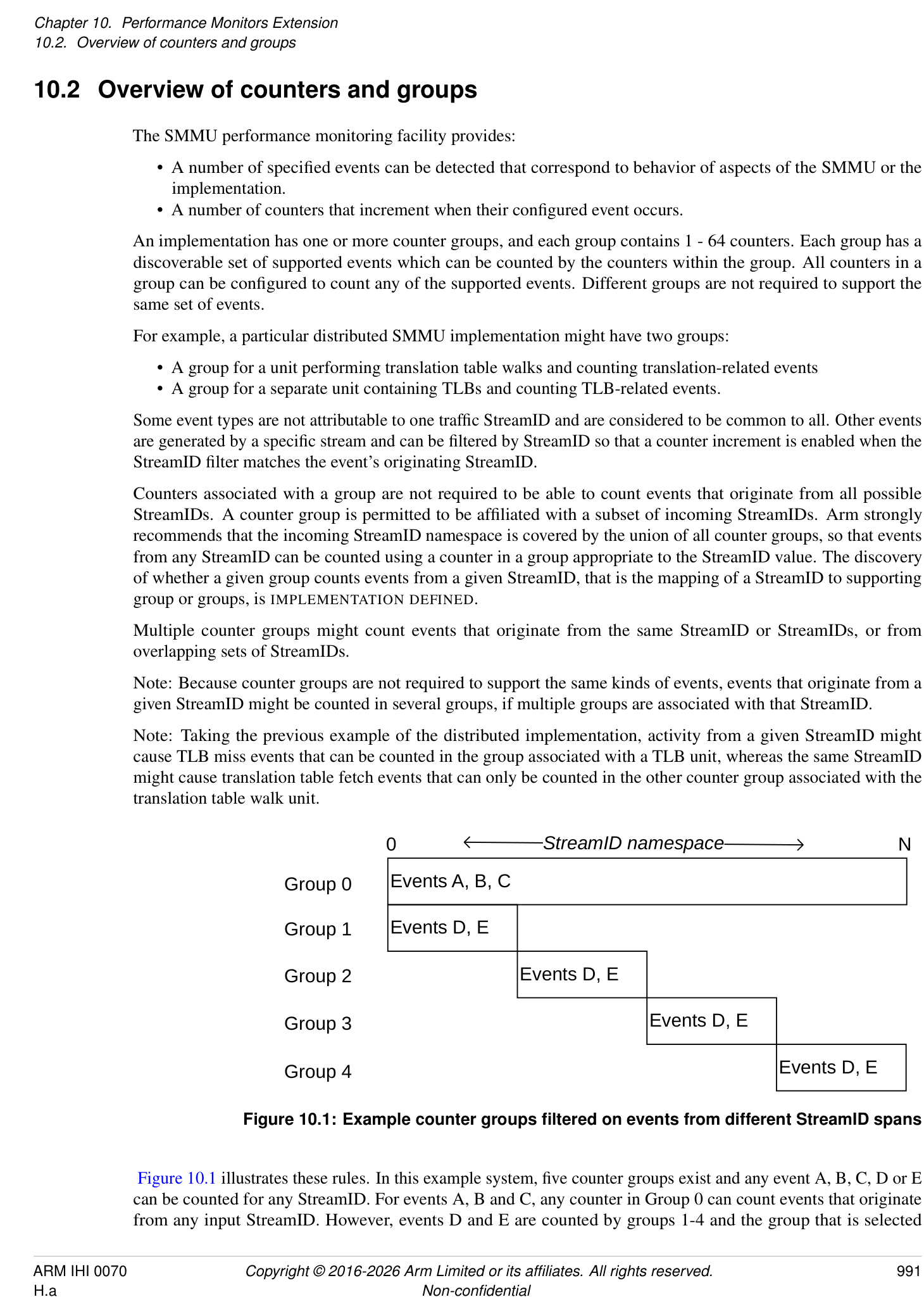
Figure 10.1 illustrates these rules. In this example system, five counter groups exist and any event A, B, C, D or E can be counted for any StreamID. For events A, B and C, any counter in Group 0 can count events that originate from any input StreamID. However, events D and E are counted by groups 1-4 and the group that is selected
depends on which services the relevant StreamIDs. For example, to count event D originating from StreamID N, a counter in Group 4 must be used.
Note: Although a counter can be configured to count an event that is filtered by StreamID N, a counter can also be configured to count an event without the StreamID filter. In the example in Figure 10.1, a counter in Group 4 could count an event that occurs from any of the StreamIDs associated with Group 4.
If a counter group exists that is associated with all StreamIDs, Arm recommends that Group 0 is used.
The association between counter groups and ranges of StreamIDs is fixed at design time and no mechanism is provided to re-configure this mapping.
A counter group is conceptually free-standing and has no interdependency on the behavior of other counter groups or even on the SMMU configuration itself. This means that:
-
A counter group can be dissimilar to other groups, for example if implemented in a different IP block to another group.
-
The capabilities of a given counter group (events captured, number of counters, MSI support) might be unique in the SMMU.
If the SMMUEN for a Security state is zero, it is IMPLEMENTATION DEFINED whether events that can be filtered by stream are counted for activity on the streams that are associated with that Security state. The Secure Observation rules in 10.6 Support for Secure state also apply if the implementation supports counting the event in this scenario.
For events that cannot be filtered by stream, it is IMPLEMENTATION DEFINED whether they are counted when all traffic through the SMMU is treated as global bypass, as indicated by SMMU_(*_)CR0.SMMUEN == 0.
Note: Event 0, “Clock cycle” is the only architectural event in this category.
Unless otherwise specified, when the configuration is changed, there is an IMPLEMENTATION SPECIFIC delay between the observation of the register write by the PMCG and the configuration change taking effect. The change is not required to affect transactions that have been observed and might be partly processed by the SMMU.
Note: Arm expects that any delay is small. Register accesses and client transactions that occur after the completion of a register access that alters the configuration are expected to observe the new configuration.
10.2.1 Overflow, interrupts and capture
An individual counter overflows when an increment causes a carry-out to be generated, that is when the counter wraps beyond its maximum unsigned value to a smaller value. When this happens, a bit is set in the Overflow Status array that corresponds to the counter that overflowed. An overflow condition does not prevent a counter from counting.
Note: Software can read the Overflow Status (OVS) array using the SMMU_PMCG_OVS{SET0,CLR0} registers to determine which counters have overflowed.
A counter can be programmed to assert a common per-counter group interrupt, when enabled, on overflow. In addition, the counter group interrupt has a per-group overall enable flag.
Note: Whether an overflow occurs is independent of, and not prevented by, the OVS status. If a counter overflow occurs, any side effects of interrupting and capturing it, if enabled, occur regardless of the value of the corresponding OVS bit.
The counter group interrupt is an edge-triggered wired interrupt output, an MSI interrupt, or both. Because counter groups might represent distinct IP blocks, MSI support can differ between counter groups that are associated with one SMMU. However, Arm strongly recommends that all counter groups support MSIs if the core SMMU supports MSIs.
Note: As with the core SMMU MSI IRQs, an implementation that supports MSIs can still supply a wired IRQ output, giving the system the choice of using the wired IRQ and leaving the MSI disabled, or using the MSI.
Optionally, a PMCG can allow all counter registers in a group to be simultaneously sampled by a capture mechanism that copies the counter values to their respective shadow register. The presence of support for this mechanism
is discovered via SMMU_PMCG_CFGR.CAPTURE == 1. The capture mechanism is triggered by one of the following:
-
A write of 1 to SMMU_PMCG_CAPR.CAPTURE.
-
Overflow of a counter configured with SMMU_PMCG_EVTYPERn.OVFCAP == 1.
- Note: The counter that causes the capture due to overflow is captured with a post-overflow value.
-
An external IMPLEMENTATION DEFINED mechanism.
When capture is triggered by a write to SMMU_PMCG_CAPR.CAPTURE, the captured values are observable to an access that is performed after the write to SMMU_PMCG_CAPR completes.
Note: One use model for the PMCG might be to program a counter to overflow within a known number of counts and, on overflow a capture is triggered and an interrupt is sent. The interrupt handler reads out the captured counter values.
Note: In addition, counter values and their overflow events can be exported in an IMPLEMENTATION DEFINED manner to external profiling logic. Export and capture of counter values through a mechanism that is invisible to the SMMU PMCG programming interface are unrelated to the presence of the programmatic capture mechanism indicated by SMMU_PMCG_CFGR.CAPTURE.
If an MSI is configured with a cacheable, shareable attribute, whether the PMCG is able to perform a cache-coherent MSI write is IMPLEMENTATION DEFINED. The core SMMU_IDR0.COHACC field does not apply to PMCG MSI writes.
When a counter that overflows is configured to trigger an interrupt, the interrupt is made observable after all of the following have become observable:
-
The update to OVS.
-
The new counter value.
-
The captured values, if the overflow that caused the interrupt also triggered a capture.
10.3 Monitor events
Performance events are indicated by a numeric ID, in the following ranges:
-
0x0000 to 0x007F: Architected events
-
0x0080 to 0xFFFF: IMPLEMENTATION DEFINED events
The architecture defines the following event types and their causes. Unless otherwise specified, “translation request” includes both ATS Translation Requests and non-ATS translation requests.
| Event ID | Description | Notes | Mandatory | Can flter on StreamID |
|---|---|---|---|---|
| 0 | Clock cycle | The period between these events is | Y | N |
| IMPLEMENTATION DEFINED. | ||||
| It is IMPLEMENTATION DEFINEDwhether this | ||||
| event is derived from a continuous time base or | ||||
| an SMMU clock which might be subject to | ||||
| IMPLEMENTATION SPECIFICgating based on | ||||
| SMMU activity. | ||||
| 1 | Translation or | For a component processing client device | Y | Y |
| request | transactions, this event counts once for each | |||
| transaction. | ||||
| For a component performing translation | ||||
| services, this event counts once for each | ||||
| translation request received from another | ||||
| component. | ||||
| This event includes transactions or translation | ||||
| requests that lead to TLB or cache misses. This | ||||
| event may include any or all of the following: | ||||
| - Terminated transactions. | ||||
| - Prefetch transactions. | ||||
| - CMOs. | ||||
| - ATOS requests. | ||||
| - HACDBS processing. | ||||
| See footnotes (1), (2), (3). | ||||
| 2 | TLB miss caused | This event is counted once when translation for | Y | Y |
| by incoming | an incoming transaction or translation request | |||
| transaction or | cannot be satisfed from internal TLB caching, | |||
| translation request | and depends on a translation table access | |||
| procedure or translation request to a different | ||||
| component. | ||||
| This event may include any or all of the | ||||
| following: | ||||
| - Terminated transactions. | ||||
| - Prefetch transactions. | ||||
| - CMOs. | ||||
| - ATOS requests. | ||||
| - HACDBS processing. | ||||
| See footnotes (1), (2), (3). |
| Event ID | Description | Notes | Mandatory | Can flter on StreamID |
|---|---|---|---|---|
| 3 | Confguration | This event is counted once when translation for | Y | Y |
| cache miss caused | an incoming transaction or translation request | |||
| by transaction or | cannot be satisfed from internal confguration | |||
| translation request | caching, and depends on a confguration table | |||
| access procedure or request to a different | ||||
| component that provides confguration | ||||
| structure access services. | ||||
| This event may include any or all of the | ||||
| following: | ||||
| - Terminated transactions. | ||||
| - Prefetch transactions. | ||||
| - CMOs. | ||||
| - ATOS requests. | ||||
| - HACDBS processing. | ||||
| See footnotes (1), (2), (3), (4). | ||||
| 4 | Translation table | External transactions performed by a | Y | Y |
| walk accesses | translation table walker, including accesses | |||
| performed speculatively. | ||||
| This applies to translation table walks | ||||
| performed for any reason including: | ||||
| - Transactions. | ||||
| - Non-ATS translation requests. | ||||
| - ATS Translation Requests. | ||||
| - ATOS requests. | ||||
| - HACDBS processing. | ||||
| - HTTU. | ||||
| - Command consumption on a DCMDQ. | ||||
| - Prefetch operations. | ||||
| 5 | Confguration | External transactions performed by a | Y | Y |
| structure access | confguration table walker, including accesses | |||
| performed speculatively. | ||||
| This includes: | ||||
| - Confguration fetches performed | ||||
| for any reason. | ||||
| - Any access to confguration | ||||
| structures caused by command | ||||
| consumption on a DCMDQ (4). | ||||
| - HACDBS processing. | ||||
| 6 | PCIe ATS | Independent of success/failure of response. | If ATS | Y |
| Translation | Note: ATS translation failures are visible at the | supported | ||
| Request received | endpoint, either through an error or because of | |||
| the endpoint causing a software-visible PRI | ||||
| Page Request. |
| Event ID | Description | Notes | Mandatory | Can flter on StreamID |
|---|---|---|---|---|
| 7 | PCIe ATS | An ATS Translated transaction was received by | If ATS | Y |
| Translated | the component. This event includes both ATS | supported | ||
| Transaction passed | Translated transactions subject to further Stage | |||
| through SMMU | 2 translation because EATS=0b10, whether | |||
| TLB/cache misses occurred or not, and those | ||||
| that bypass translation. | ||||
| This event may include terminated transactions | ||||
| (1). | ||||
| Note: Translated transactions might bypass or | ||||
| be subject to further translation, asSTE.EATS | ||||
| dictates. |
-
(1) It is IMPLEMENTATION DEFINED whether events 1, 2, 3 and 7 include transactions terminated by the SMMU. Arm recommends that terminated transactions are included in all of, or none of, events 1, 2, 3 and 7.
-
(2) For each of the following, it is IMPLEMENTATION DEFINED whether they are included in events 1, 2 and 3:
-
Speculative transactions, prefetch transactions or prefetch commands from client devices or other components.
-
ATOS requests.
-
Cache Maintenance Operations (CMOs).
Arm recommends that each of these options are either included in all of, or none of, events 1, 2 and 3.
-
(3) It is IMPLEMENTATION DEFINED if this event applies to command consumption on a DCMDQ.
-
(4) If the SID translation feature is supported, it is IMPLEMENTATION DEFINED defined whether the structures required for vSID translation are included in the configuration structures that affect Events 3 and 5.
If granule protection checks are enabled, Event IDs 2 and 4 count accesses to the GPT, when a GPT access is performed. See also: 3.25 Granule Protection Checks . The other architected PMCG events do not count accesses to the GPT. IMPLEMENTATION DEFINED events are permitted to count GPT accesses, GPT-related TLB hits or GPT-related TLB misses for the appropriate Security state.
If DPT is enabled, Event IDs 2 and 4 count DPT lookups for components that support DPT checks. See also: 3.24.3 DPT format and lookup process .
Note: In the case where the SMMU is not permitted to generate a Device Access fault based on an existing DPT TLB entry and a DPT walk is required, event 2 is counted. See also: 3.24.2.1 DPT TLB caching and Device Access faults .
PMCG events for configuration cache hits, misses and fetches for the STE lookups required by the DPT check are counted in the same manner as any other configuration-related event.
IMPLEMENTATION DEFINED events are permitted to count DPT accesses, DPT-related TLB hits or DPT-related TLB misses.
Counting of DPT lookups and accesses to the GPT is subject to the general filtering requirements in section 10.4 StreamIDs and filtering .
It is IMPLEMENTATION DEFINED whether a transaction that is retried (for any reason) is re-counted. If it is re-counted, it appears exactly like a new transaction and all relevant events are re-counted. If it is not re-counted, no counters are triggered.
When an event is mandatory, the following are both true:
-
The event is supported in at least one counter group.
-
The event is supported in as many groups as required to make the event countable for all possible StreamIDs in use.
-
Note: In a component that only caches TLB and configuration data in a single combined cache, events 2 and 3 count the same occurrence (a miss of the combined cache is a miss of both configuration and translation).
Note: As an example, a distributed implementation might have different roles for different components (and therefore different PMCGs), so that one component might translate transactions from client devices and another component handles translation requests for the former. The first component has no table walker so it is not required to count events 4 and 5. These events are instead counted by the second component, which performs configuration and translation table walks. The second component could still include TLBs and configuration caches, in which case it would also count events 2 and 3.
10.4 StreamIDs and filtering
Some event types might be filtered by StreamID, so that events are only counted if they are associated with transactions that match the configured StreamID filter. Other event types are considered unrelated to any particular StreamID and are counted by any counter that is configured to count the event (any StreamID filtering configuration is ignored). An implementation provides a StreamID filter per counter, or one StreamID filter that applies to all counters in the PMCG. This is identified through the SMMU_PMCG_CFGR.SID_FILTER_TYPE field.
When SMMU_PMCG_CFGR.SID_FILTER_TYPE == 0, the StreamID filter configuration is controlled by register fields for each counter. SMMU_PMCG_EVTYPERn.{FILTER_SID_SPAN,FILTER_SEC_SID} and SMMU_PMCG_SMRn.STREAMID are associated with counter n as accessed through SMMU_PMCG_EVCNTRn.
When SMMU_PMCG_CFGR.SID_FILTER_TYPE == 1, the fields SMMU_PMCG_EVTYPER0.{FILTER_SID_SPAN, FILTER_SEC_SID} and SMMU_PMCG_SMR0.STREAMID apply to all counters in the group.
When the corresponding counter is configured to count an event type that can be filtered by StreamID, this configuration allows filtering by:
-
Exact StreamID match.
-
Partial StreamID match where a variable span of StreamID[N:0] are ignored and only upper StreamID bits are required to match the given filter.
-
Match any StreamID (filtering disabled).
There are four configuration modes for filtering events by StreamID and SEC_SID which depend on the values configured in SMMU_PMCG_EVTYPERn.FILTER_SID_SPAN and SMMU_PMCG_SMRn.STREAMID as follows:
| Mode | Condition |
|---|---|
| ExactSID | FILTER_SID_SPAN = 0 |
| PartialSID | FILTER_SID_SPAN = 1, and STREAMID is a mask that is neither: |
| - All-ones in all implemented bits. | |
| - All-ones except for the most signifcant implemented bit. | |
| AllSIDOneSECSID | FILTER_SID_SPAN = 1, and STREAMID is a mask that is all-ones except for the |
| most-signifcant implemented bit. | |
| AllSIDManySECSID | FILTER_SID_SPAN = 1, and STREAMID is a mask that is all-ones in all implemented bits. |
When a counter uses the ExactSID mode, SMMU_PMCG_SMRn.STREAMID is programmed with a StreamID that is matched exactly. Events that are associated with other StreamIDs do not cause an increment of the counter.
When a counter uses the PartialSID mode, which allows matching a partial StreamID, where the X most-significant bits must match but the Y least-significant bits might differ, SMMU_PMCG_SMRn.STREAMID is programmed with a value that contains:
-
STREAMID[Y - 1] == 0. That is, the most significant bit in the group of bits that do not need to match is zero.
-
STREAMID[(Y - 2):0] bits are all programmed to 1 (where Y > 1).
-
The remainder of implemented bits of STREAMID (the X most-significant bits, from bit Y upwards) contain a value that will match the corresponding bits of event StreamID.
-
Examples (in binary):
- 0000:0000:0001:1011:1111:0111:1111:0111 matches 0000:0000:0001:1011:1111:0111:1111:xxxx
-
0000:0000:0001:1011:1111:0111:1111:0110 matches 0000:0000:0001:1011:1111:0111:1111:011x
-
0000:0000:0001:1011:1111:0101:1111:1111 matches
-
0000:0000:0001:1011:1111:01xx:xxxx:xxxx
The AllSIDOneSECSID mode, which allows matching all the StreamIDs of one Security state, is a particular case of the PartialSID mode, where Y is equal to SMMU_IDR0.SIDSIZE.
When a counter uses the AllSIDManySECSID mode, which matches any StreamID regardless of its Security state, SMMU_PMCG_SMRn.STREAMID is programmed with 1 for all implemented bits:
-
Note: The STREAMID field might implement fewer bits than the SMMU StreamID size. Arm recommends that 0xFFFFFFFF is written to this field to ensure that all implemented bits are set without first determining how many bits to write.
-
Note: A value with 0 in the most-significant implemented bit and 1 in all bits below that point is an alternative encoding that matches any StreamID. This is the maximum mask given the encoding of the variable mask size, but requires knowledge of the implemented field size. When Secure state is supported, this encoding behaves differently to the “all 1” encoding in terms of the scope of filtering according to SEC_SID.
When the PMCG implements support for Secure state (see section 10.6 Support for Secure state ):
-
The SMMU_PMCG_EVTYPERn.FILTER_SEC_SID flag determines whether the StreamID filter configuration (as determined by SMMU_PMCG_EVTYPERn.FILTER_SID_SPAN and SMMU_PMCG_SMRn.STREAMID) applies to the Secure or the Non-secure StreamID namespace. Secure observation can be disabled so that StreamID matching can only match events that are associated with Non-secure StreamIDs, overriding the effective value of this flag.
-
When SMMU_PMCG_EVTYPERn.FILTER_SID_SPAN == 1 and SMMU_PMCG_SMRn.STREAMID field is programmed with 1 in all implemented bits, the filter matches all StreamIDs for both Secure and Non-secure namespaces if Secure observation is enabled, and matches all Non-secure StreamIDs if Secure observation is not enabled. In SMMUv3.0, it is IMPLEMENTATION DEFINED whether:
-
The filter matches all StreamIDs in one of the Secure or Non-secure namespaces as determined by the effective value of the SMMU_PMCG_EVTYPERn.FILTER_SEC_SID flag.
-
The filter matches all StreamIDs for both Secure and Non-secure namespaces if Secure observation is enabled, and matches all Non-secure StreamIDs if Secure observation is not enabled.
-
-
When SMMU_PMCG_EVTYPERn.FILTER_SID_SPAN == 1 and SMMU_PMCG_SMRn.STREAMID is programmed with 0 in the most-significant implemented bit and 1 in all other implemented bits, the filter matches all StreamIDs for the Secure or the Non-secure namespace as determined by the effective value of the SMMU_PMCG_EVTYPERn.FILTER_SEC_SID flag.
When PMCG implements support for Realm state, in ExactSID, PartialSID and AllSIDOneSECSID modes, StreamID filtering is applied, and SEC_SID filtering is applied as described in the table below, where Rel and Sec are defined as:
-
Rel = SMMU_PMCG_EVTYPERn.FILTER_REALM_SID & SMMU_PMCG_ROOTCR.RLO;
-
Sec = SMMU_PMCG_EVTYPERn.FILTER_SEC_SID & SMMU_PMCG_SCR.SO;
| Rel | Sec | Result |
|---|---|---|
| 0 | 0 | Count only Non-secure events. |
| 0 | 1 | Count only Secure events. |
| 1 | 0 | Count only Realm events. |
| 1 | 1 | Reserved, behaves as {0, 0}. |
When PMCG implements support for Realm state, in AllSIDManySECSID mode, StreamID
filtering is not applied and SEC_SID filtering is applied as follows, according to the values of SMMU_PMCG_EVTYPERn.{FILTER_REALM_SID, FILTER_SEC_SID}, SMMU_PMCG_SCR.SO and SMMU_PMCG_ROOTCR.{RTO, RLO, SAO}:
If FILTER_REALM_SID = 0 then:
-
Non-secure events are counted.
-
If SO = 1 then Secure events are additionally counted.
If FILTER_REALM_SID = 1 then:
-
If FILTER_SEC_SID = 0 then:
-
Non-secure events are counted.
-
If RLO = 1 then Realm events are additionally counted.
-
-
If FILTER_SEC_SID = 1 then:
-
Non-secure events are counted.
-
If SO = 1 then Secure events are additionally counted.
-
If RLO = 1 then Realm events are additionally counted.
-
If RTO = 1 then NoStreamID accesses to Root PA space are additionally counted.
-
If SAO = 1 then NoStreamID accesses to SA PA space are additionally counted.
-
For the purposes of counting events for NoStreamID accesses, the Security state of the access is defined as follows:
-
If the target PA space of the access is NS, Realm, Secure, SA or Root, then it is treated as conveying the Security state of the access.
-
Otherwise (including if the target PA space of the access is NSP), then the Security state is Non-secure.
Accesses with the PM attribute are counted in the same manner as accesses without the PM attribute, with the exception that accesses with PM = 1 are counted only if SMMU_PMCG_ROOTCR.PMO = 1.
Note: This applies to any access with PM = 1, regardless of the output PA space. See section 3.25.10.1.1 Protected Mode .
10.4.1 Counter Group StreamID size
The StreamID that is handled by a PMCG is not required to be the full SMMU-architectural StreamID as seen by the SMMU programming interface. This arises from the possibility that a PMCG represents a sub-component of the SMMU and, in a distributed implementation, the component might only service a subset of the StreamID space of the SMMU. In such an implementation, the upper bits of StreamID might be considered fixed for a given sub-component. For example, block 0 serves clients with StreamIDs 0x00 to 0x0F and block 1 serves clients with StreamIDs 0x10 to 0x1F.
In all cases, the low-order PMCG StreamID bits [N:0] must be equivalent to the SMMU StreamID[N:0]. Where a PMCG StreamID filter is programmed, SMMU_PMCG_SMRn.STREAMID might implement fewer bits than indicated by SMMU_IDR1.SIDSIZE in the SMMU with which the PMCG is associated. The implemented size of the SMMU_PMCG_SMRn.STREAMID field is IMPLEMENTATION DEFINED. The association between the span of StreamIDs served by a given PMCG and the overall SMMU StreamID namespace is IMPLEMENTATION DEFINED.
For example, an SMMU with a 17-bit StreamID might be composed of two components A and B, which support client devices with StreamIDs 0 to 0xFFFF and 0x10000 to 0x1FFFF respectively. In order to count events from the client device with StreamID 0x12345, software programs a counter in the PMCG that is associated with component B to filter on StreamID 0x12345. However, SMMU_PMCG_SMRn.STREAMID might only implement 16 bits and read back the value 0x02345.
Software must not depend on readback of SMMU_PMCG_SMRn.STREAMID returning the full SMMU StreamID. The readback value might be truncated to the PMCG StreamID size.
10.4.2 Counting of NoStreamID accesses
NoStreamID accesses are permitted to cause events to be counted, subject to all of the following constraints:
-
For the purposes of PMCG filtering, the Security state of a NoStreamID access is defined as follows: – If the target PA space of the access is NS, Realm, Secure, SA or Root, then it is treated as conveying the Security state of the access. Note: If the target PA space of the access is SA, then the access is counted only in AllSIDManySECSID mode, subject to the value of SMMU_PMCG_ROOTCR.SAO. See section 3.25.10 Granular Data Isolation .
- Otherwise (including if the target PA space of the access is NSP), then the Security state is Non-secure.
-
NoStreamID accesses are only counted if counting of events for their effective Security state is enabled.
-
NoStreamID accesses are only counted if SMMU_PMCG_EVTYPERn.FILTER_SID_SPAN == 1, and SMMU_PMCG_SMRn.STREAMID is programmed to count accesses from all streams, and that selection of all streams includes the effective Security state of the NoStreamID accesses. Note: This is when SMMU_PMCG_SMRn.STREAMID is all-ones in all implemented bits, or all-ones in all implemented bits except for the most-significant bit.
-
NoStreamID accesses to the NSP PA space are counted in the same manner as NoStreamID accesses to the NS PA space, with the exception that such accesses are counted only if SMMU_PMCG_ROOTCR.PMO is 1.
Note: These requirements mean that if FILTER_REALM_SID is zero, or not implemented, then no PMCG events are counted for accesses from NoStreamID devices to Root or Realm physical address spaces.
When a NoStreamID access is permitted to cause events to be counted, then it can count:
-
Event ID 1 for the NoStreamID transaction.
-
Event IDs 2 and 4 for the GPT-related events, as described in section 10.3 Monitor events .
-
IMPLEMENTATION DEFINED GPT-related events.
See also:
- 3.25.1.1 GPC for client devices without a StreamID .
10.4.3 PARTID- and PMG-based filtering
If SMMU_PMCG_CFGR.FILTER_PARTID_PMG == 1, then the PMCG supports filtering of events by MPAM PARTID and PMG.
When PARTID- or PMG-based filtering is enabled in a particular SMMU_PMCG_EVTYPERn register, the SMMU PMCG uses the PARTID and/or PMG values configured in the corresponding SMMU_PMCG_SMRn register to filter events that are counted in the corresponding SMMU_PMCG_EVTYPERn register.
Filtering by PARTID and PMG can be enabled independently, using the configuration bits SMMU_PMCG_EVTYPERn.{FILTER_PARTID, FILTER_PMG, FILTER_MPAM_NS}.
In an SMMU implementation with RME DA, SMMU_PMCG_EVTYPERn.FILTER_MPAM_NS is replaced by a 2-bit field, FILTER_MPAM_SP. This change is architected such that the values of FILTER_MPAM_NS directly match the first two values of FILTER_MPAM_SP. See SMMU_PMCG_EVTYPERn.
If filtering by PARTID and/or PMG is enabled, then filtering by StreamID is not available.
When filtering by PARTID, the SMMU compares the PARTID value configured in SMMU_PMCG_SMRn to the output PARTID of each transaction or SMMU-originated access, whether that comes from SMMU_(S_)GBPMPAM, SMMU_(*_)GMPAM, the STE or the CD.
When filtering by PMG, the SMMU compares the PMG value configured in SMMU_PMCG_SMRn to the output PMG of each transaction or SMMU-originated access, whether that comes from SMMU_(S_)GBPMPAM, the STE or the CD.
It is IMPLEMENTATION DEFINED whether an SMMU PMCG can filter events 3 and 5 by PARTID and PMG.
For each IMPLEMENTATION DEFINED event, it is IMPLEMENTATION DEFINED whether an SMMU PMCG can filter that event by PARTID and PMG.
If an SMMU PMCG is configured to filter an event by PARTID or PMG and the SMMU does not support filtering by PARTID or PMG for that event ID, the event is counted without filtering.
Note: If filtering by PARTID or PMG is supported and enabled for an event ID and a transaction is terminated before it was assigned with a PARTID and PMG then it is IMPLEMENTATION DEFINED if an event arising from that transaction is counted.
If an SMMU PMCG is configured to filter a filterable event by PARTID or PMG values exceeding those advertised in SMMU_PMCG_(S_)MPAMIDR, it counts no events.
| Event ID | Description | Can flter by PARTID or PMG |
|---|---|---|
| 0 | Clock cycle | No |
| 1 | Transaction or request | Yes |
| 2 | TLB miss caused by incoming transaction or | Yes |
| translation request | ||
| 3 | Confguration cache miss caused by transaction or | IMPLEMENTATION DEFINED |
| translation request | ||
| 4 | Translation table walk access | Yes |
| 5 | Confguration structure access | IMPLEMENTATION DEFINED |
| 6 | PCIe ATS Translation Request received | Yes |
| 7 | PCIe ATS Translated Transaction passed through | Yes |
| SMMU |
10.4.4 Counting of non-attributable events
A non-attributable event is an event that is not directly associated with a single Security state, but might reveal information about a Security state.
Note: None of the architected SMMUv3 events are non-attributable events.
If Realm state is not implemented and Secure state is implemented, non-attributable events are only counted if SMMU_PMCG_SCR.SO is 1.
If the Realm programming interface is present, then non-attributable events are only counted if all of the following are true:
-
SMMU_PMCG_ROOTCR.NAO is 1.
-
Either or both of SMMU_PMCG_SCR.SO and SMMU_PMCG_SCR.NAO are 1.
10.5 Registers
The total number of counter groups that are associated with one SMMU is IMPLEMENTATION DEFINED. Each counter group is represented by one 4KB page (Page 0) with one optional additional 4KB page (Page 1), both of which are at IMPLEMENTATION DEFINED base addresses.
If Page 1 is present, the registers for counter values, overflow status and shadow capture control appear in Page 1 instead of Page 0. Presence is indicated by SMMU_PMCG_CFGR.RELOC_CTRS. Arm recommends that Page 1 is implemented and, if so, Arm strongly recommends that Page 1 is located within an aligned 64KB system address span that is otherwise unused.
Note: This permits a hypervisor to use a 64KB stage 2 granule to expose the Page 1 counter values for direct access by a virtual machine. Arm expects that guest access to stage 1 registers (for counter configuration) will be trapped and controlled by the hypervisor, rather than accessed directly.
Access behaviors follow the same rules as for the SMMU registers described in section 6.2 Register overview . In particular:
-
Aligned 32-bit access is permitted to 64-bit registers.
-
It is IMPLEMENTATION DEFINED whether 64-bit accesses to 64-bit registers are atomic.
-
All registers are little-endian.
Unless otherwise specified, software is permitted to read or write a register at any time. Writes to read-only registers are IGNORED.
10.5.1 SMMU_PMCGn address map
The map of the base PMCG register Page 0 is shown here:
| Offset | Register | Notes |
|---|---|---|
| 0x000 | SMMU_PMCG_EVCNTRn | 32- or 64-bit, RW, 0 <= n < 64 |
| + | Registers placed on a 4-byte stride if | |
| stride*n | SMMU_PMCG_CFGR.SIZE <= 31 (counters 32-bit or smaller), | |
| (0x000 | otherwise an 8-byte stride. | |
| to | ||
| 0x1FF) | ||
| 0x400 | SMMU_PMCG_EVTYPERn | 32-bit, RW, 0 <= n < 64 |
| + 4*n | ||
| (0x400 | ||
| to | ||
| 0x4FF) | ||
| 0x600 | SMMU_PMCG_SVRn | 32- or 64-bit, RO, 0 <= n < 64 |
| + | Stride same as forSMMU_PMCG_EVCNTRn. | |
| stride*n | ||
| (0x600 | ||
| to | ||
| 0x7FF) | ||
| 0xA00 | SMMU_PMCG_SMRn | 32-bit, RW, 0 <= n < 64 |
| + 4*n | ||
| (0xA00 | ||
| to | ||
| 0xAFF) |
| Offset | Register | Notes |
|---|---|---|
| 0xC00 | SMMU_PMCG_CNTENSET0 | 64-bit, RW |
| 0xC20 | SMMU_PMCG_CNTENCLR0 | 64-bit, RW |
| 0xC40 | SMMU_PMCG_INTENSET0 | 64-bit, RW |
| 0xC60 | SMMU_PMCG_INTENCLR0 | 64-bit, RW |
| 0xC80 | SMMU_PMCG_OVSCLR0 | 64-bit, RW |
| 0xCC0 | SMMU_PMCG_OVSSET0 | 64-bit, RW |
| 0xD88 | SMMU_PMCG_CAPR | 32-bit, WO |
| 0xDF8 | SMMU_PMCG_SCR | 32-bit, Secure, RW |
| 0xE00 | SMMU_PMCG_CFGR | 32-bit, RO |
| 0xE04 | SMMU_PMCG_CR | 32-bit, RW |
| 0xE08 | SMMU_PMCG_IIDR | 32-bit, RO |
| 0xE20 | SMMU_PMCG_CEID0 | 64-bit, RO |
| 0xE28 | SMMU_PMCG_CEID1 | 64-bit, RO |
| 0xE40 | Alias ofSMMU_PMCG_SCR, otherwise | 32-bit, Secure, RW |
| RAZ/WI | ||
| 0xE48 | SMMU_PMCG_ROOTCR | 32-bit, Root, RW |
| 0xE50 | SMMU_PMCG_IRQ_CTRL | 32-bit, RW |
| 0xE54 | SMMU_PMCG_IRQ_CTRLACK | 32-bit, RO |
| 0xE58 | SMMU_PMCG_IRQ_CFG0 | 64-bit, RW |
| 0xE60 | SMMU_PMCG_IRQ_CFG1 | 32-bit, RW |
| 0xE64 | SMMU_PMCG_IRQ_CFG2 | 32-bit, RW |
| 0xE68 | SMMU_PMCG_IRQ_STATUS | 32-bit, RO |
| 0xE6C | SMMU_PMCG_GMPAM | 32-bit, RW |
| 0xE70 | SMMU_PMCG_AIDR | 32-bit, RO |
| 0xE74 | SMMU_PMCG_MPAMIDR | 32-bit, RO |
| 0xE78 | SMMU_PMCG_S_MPAMIDR | 32-bit, Secure, RO |
| Offset | Register | Notes |
|---|---|---|
| 0xE80 | IMPLEMENTATION DEFINED | |
| - | ||
| 0xEFF | ||
| 0xFB0 | SMMU_PMCG_ID_REGS | IMPLEMENTATION DEFINED |
| - | ||
| 0xFFF | ||
| When Page 1 is present (SMMU_PMCG_CFGR.RELOC_CTRS == 1), the following registers are relocated to | ||
| Page 1 and their corresponding Page 0 locations become RES0. Offsets are shown relative to the base address of | ||
| Page 1. | ||
| Offset | Register | Notes |
| 0x000 + | SMMU_PMCG_EVCNTRn | Same as for corresponding locations in Page 0. |
| n*stride | ||
| (0x000 | ||
| to | ||
| 0x1FF) | ||
| 0x600 + | SMMU_PMCG_SVRn | |
| n*stride | ||
| (0x600 | ||
| to | ||
| 0x7FF) | ||
| 0xC80 | SMMU_PMCG_OVSCLR0 | |
| 0xCC0 | SMMU_PMCG_OVSSET0 | |
| 0xD88 | SMMU_PMCG_CAPR |
10.5.2 Register details
10.5.2.1 SMMU_PMCG_EVCNTR<n>, n = 0 - 63
The SMMU_PMCG_EVCNTR<n> characteristics are:
Purpose
Provides Counters for PMCG events.
Configuration
When counter size is <= 32 bits (SMMU_PMCG_CFGR.SIZE <= 31), these registers are 32 bits in size. Otherwise, these registers are 64 bits in size. Present in an array of n registers, all of size 32 or 64, each corresponding to counter n.
The counter value is incremented when an event matching SMMU_PMCG_EVTYPERn.EVENT occurs, the counter is enabled (the respective CNTEN == 1) and, if the event type is filterable by StreamID, filters match. See section 10.4 StreamIDs and filtering for information on filtering.
When a counter value is incremented by the PMCG, the increment is atomic with respect to external writes to this register.
Registers corresponding to unimplemented counters are RES0.
Attributes
SMMU_PMCG_EVCNTR<n> is a:
-
32-bit register when UInt(SMMUv3_PMCG.SMMU_PMCG_CFGR.SIZE) <= 31.
-
64-bit register when UInt(SMMUv3_PMCG.SMMU_PMCG_CFGR.SIZE) > 31.
This register is part of the SMMUv3_PMCG block.
Field descriptions
When UInt(SMMUv3PMCG.SMMUPMCGCFGR.SIZE) <= 31:
31 0
COUNTER_VALUE
COUNTERVALUE, bits [31:0]
Counter value[N:0].
R == SMMU_PMCG_CFGR.SIZE + 1.
If R < 32, bits [31:R] are RES0.
The reset behavior of this field is:
- This field resets to an UNKNOWN value.
When UInt(SMMUv3PMCG.SMMUPMCGCFGR.SIZE) > 31:
| 63 | 32 | |
|---|---|---|
| COUNTER_VALUE | ||
| 31 | 0 | |
| COUNTER_VALUE |
COUNTERVALUE, bits [63:0]
Counter value[N:0].
- R == SMMU_PMCG_CFGR.SIZE + 1.
If R > 32 and R < 64, bits [63:R] are RES0.
The reset behavior of this field is:
- This field resets to an UNKNOWN value.
Accessing SMMUPMCGEVCNTR<n>
Accesses to this register use the following encodings:
When UInt(SMMUv3PMCG.SMMUPMCGCFGR.SIZE) <= 31
Accessible at offset 0x000 + (4 * n) from SMMUv3_PMCG
-
When an access is Non-secure, the PMCG supports Secure state, and SMMUv3_PMCG.SMMU_PMCG_SCR.NSRA == ‘0’, accesses to this register are RAZ/WI.
-
Otherwise, accesses to this register are RW.
When UInt(SMMUv3PMCG.SMMUPMCGCFGR.SIZE) > 31
Accessible at offset 0x000 + (8 * n) from SMMUv3_PMCG
-
When an access is Non-secure, the PMCG supports Secure state, and SMMUv3_PMCG.SMMU_PMCG_SCR.NSRA == ‘0’, accesses to this register are RAZ/WI.
-
Otherwise, accesses to this register are RW.
10.5.2.2 SMMU_PMCG_EVTYPER<n>, n = 0 - 63
The SMMU_PMCG_EVTYPER<n> characteristics are:
Purpose
These registers contain per-counter configuration, in particular the event type counted.
Configuration
There are no configuration notes.
Attributes
SMMU_PMCG_EVTYPER<n> is a 32-bit register.
This register is part of the SMMUv3_PMCG block.
Field descriptions
31 30 29 28 27 20 19 18 17 16 15 0
RES0 EVENT
OVFCAP FILTER_PARTID
FILTER_SEC FILTER_PMG
_SID FILTER_MPAM_SP
FILTER_SID_SP FILTER_REALM_SID
AN
OVFCAP, bit [31]
When SMMUPMCGCFGR.CAPTURE == 1:
Overflow capture.
| OVFCAP | Meaning |
|---|---|
| 0b0 | An overfow of counter n does not trigger a capture of all counters. |
| 0b1 | An overfow of counter n triggers a capture of all counters in the same way as by |
| SMMU_PMCG_CAPR.CAPTURE. |
The reset behavior of this field is:
• This field resets to an UNKNOWN value.
Otherwise:
Reserved, RES0.
FILTERSECSID, bit [30]
When n == 0 or SMMUPMCGCFGR.SIDFILTERTYPE == 0:
Filter Secure StreamIDs.
| FILTER_SEC_SID | Meaning |
|---|---|
| 0b0 | Count events originating from Non-secure |
| StreamIDs. | |
| 0b1 | Count events originating from Secure |
| StreamIDs. |
-
This bit is RES0 if the PMCG does not implement support for Secure state. Otherwise, this bit is effectively 0 if support for Secure state is implemented but Secure observation is disabled (SMMU_PMCG_SCR.SO == 0).
-
For event types that can be filtered on StreamID, this bit is considered in conjunction with FILTER_SID_SPAN and SMMU_PMCG_SMRn.STREAMID to determine how filtering is applied, based on StreamID and SEC_SID. See section 10.4 StreamIDs and filtering .
The reset behavior of this field is:
- This field resets to an UNKNOWN value.
Otherwise:
Reserved, RES0.
FILTERSIDSPAN, bit [29]
When n == 0 or SMMUPMCGCFGR.SIDFILTERTYPE == 0:
Filter StreamID.
| FILTER_SID_SPAN | Meaning |
|---|---|
| 0b0 | SMMU_PMCG_SMRn.STREAMID flters event on an exact |
| StreamID match, if the event type can be fltered on StreamID. | |
| 0b1 | TheSMMU_PMCG_SMRn.STREAMID feld encodes a match |
| span of StreamID values. See 10.4_StreamIDs and fltering_. |
Note: The span can encode ALL, equivalent to disabling filtering on StreamID. The reset behavior of this field is:
- This field resets to an UNKNOWN value.
Otherwise:
Reserved, RES0.
FILTERREALMSID, bit [28]
When SMMU_PMCG_ROOTCR.ROOTCR_IMPL == 1 and (n == 0 or SMMU_PMCG_CFGR.SID_FILTER_TYPE == 0):
Count events relating to Realm StreamIDs.
| FILTER_REALM_SID | Meaning |
|---|---|
| 0b0 | Do not count events relating to Realm |
| StreamIDs. | |
| 0b1 | Count events relating to Realm |
| StreamIDs. |
If SMMU_PMCG_ROOTCR.RLO is 0, this bit is treated as 0 for all purposes other than read back of the bit value.
The reset behavior of this field is:
- This field resets to an UNKNOWN value.
Otherwise:
Reserved, RES0.
Bits [27:20]
Reserved, RES0.
FILTERMPAMSP, bits [19:18]
When SMMU_PMCG_CFGR.FILTER_PARTID_PMG == 1 and (n == 0 or SMMU_PMCG_CFGR.SID_FILTER_TYPE == 0):
Select MPAM_SP for SMMU_PMCG_SMRn.{PARTID, PMG}.
SMMU_PMCG_SMRn.{PARTID, PMG} are treated as belonging to the following PARTID spaces:
| FILTER_MPAM_SP | Meaning |
|---|---|
| 0b00 | IfSMMU_PMCG_SCR.SO is 1 then Secure. Otherwise |
| treated as 0b01. | |
| 0b01 | Non-secure. |
| 0b10 | Reserved, behaves as 0b00. |
| 0b11 | IfSMMU_PMCG_ROOTCR.RLO is 1 then Realm. Otherwise |
| treated as 0b01. |
If SMMU_PMCG_ROOTCR.ROOTCR_IMPL = 0 then bit [19] is RES0, and bit [18] selects only between Non-secure and Secure PARTID space.
The reset behavior of this field is:
- This field resets to an UNKNOWN value.
Otherwise:
Reserved, RES0.
FILTERPMG, bit [17]
When SMMU_PMCG_CFGR.FILTER_PARTID_PMG == 1 and (n == 0 or SMMU_PMCG_CFGR.SID_FILTER_TYPE == 0):
Filter events by the value specified in SMMU_PMCG_SMRn.PMG.
| FILTER_PMG | Meaning |
|---|---|
| 0b0 | Events are not fltered by PMG. |
| 0b1 | Only count events associated with the PMG specifed in |
| SMMU_PMCG_SMRn.PMG. |
The reset behavior of this field is:
- This field resets to an UNKNOWN value.
Otherwise:
Reserved, RES0.
FILTERPARTID, bit [16]
When SMMU_PMCG_CFGR.FILTER_PARTID_PMG == 1 and (n == 0 or SMMU_PMCG_CFGR.SID_FILTER_TYPE == 0):
Filter events by the value specified in SMMU_PMCG_SMRn.PARTID.
| FILTER_PARTID | Meaning |
|---|---|
| 0b0 | Events are not fltered by PARTID. |
| 0b1 | Only count events associated with the PARTID specifed in |
| SMMU_PMCG_SMRn.PARTID. |
The reset behavior of this field is:
- This field resets to an UNKNOWN value.
Otherwise:
Reserved, RES0.
EVENT, bits [15:0]
Event.
-
Event type that causes this counter to increment.
-
An IMPLEMENTATION DEFINED number of low-order bits of this register are implemented, unimplemented upper bits are RES0.
The reset behavior of this field is:
- This field resets to an UNKNOWN value.
Additional Information
When SMMU_PMCG_CFGR.SID_FILTER_TYPE == 0, the field FILTER_SID_SPAN and, if Secure state is supported, FILTER_SEC_SID, are present in every implemented SMMU_PMCG_EVTYPERn register and correspond to counter SMMU_PMCG_EVCNTRn for all implemented values of n.
When SMMU_PMCG_CFGR.SID_FILTER_TYPE == 1, these fields are present only in SMMU_PMCG_EVTYPER0 and the FILTER_SID_SPAN and FILTER_SEC_SID fields in SMMU_PMCG_EVTYPERx, for x >= 1, are RES0.
The same relationship with SMMU_PMCG_CFGR.SID_FILTER_TYPE applies to FILTER_PARTID, FILTER_PMG and FILTER_MPAM_NS.
See SMMU_PMCG_SMRn and 10.4 StreamIDs and filtering for information on StreamID filtering. When filtering is enabled, an event is counted only if it matches the filter conditions for the counter.
Note: Event types that cannot be filtered on StreamID are always counted, as they cannot be filtered out using FILTER_* configuration.
If FILTER_PARTID == 1 or FILTER_PMG == 1, FILTER_SID_SPAN is IGNORED and events are not filtered by StreamID.
If FILTER_PARTID == 0 and FILTER_PMG == 0, FILTER_MPAM_NS is IGNORED.
See SMMU_PMCG_SMRn and 10.4.3 PARTID- and PMG-based filtering for information on PARTIDand PMG-based filtering. When filtering is enabled, an event is counted only if it matches the filter conditions for the counter.
Note: Event types that cannot be filtered on PARTID and PMG are always counted, as they cannot be filtered out using FILTER_* configuration.
Registers corresponding to unimplemented counters are RES0.
Accessing SMMUPMCGEVTYPER<n>
Accesses to this register use the following encodings:
Accessible at offset 0x400 + (4 * n) from SMMUv3_PMCG
-
When an access is Non-secure, the PMCG supports Secure state, and SMMUv3_PMCG.SMMU_PMCG_SCR.NSRA == ‘0’, accesses to this register are RAZ/WI.
-
Otherwise, accesses to this register are RW.
10.5.2.3 SMMU_PMCG_SVR<n>, n = 0 - 63
The SMMU_PMCG_SVR<n> characteristics are:
Purpose
PMCG Shadow value, 0 <= n < 64.
Configuration
When counter size is <= 32 bits (SMMU_PMCG_CFGR.SIZE <= 31), these registers are 32 bits in size. Otherwise, these registers are 64 bits in size. Present in an array of registers (all of size 32 or 64) each corresponding to counter n.
When counter value capture is implemented (SMMU_PMCG_CFGR.CAPTURE == 1), these registers hold the captured counter values of the corresponding entries in SMMU_PMCG_EVCNTRn. Registers corresponding to unimplemented counters are RES0.
If counter value capture is not implemented (SMMU_PMCG_CFGR.CAPTURE == 0), all SMMU_PMCG_SVRn registers are RES0.
This register is present only when SMMU_PMCG_CFGR.CAPTURE == 1. Otherwise, direct accesses to SMMU_PMCG_SVR<n> are RES0.
Attributes
SMMU_PMCG_SVR<n> is a:
-
32-bit register when UInt(SMMUv3_PMCG.SMMU_PMCG_CFGR.SIZE) <= 31.
-
64-bit register when UInt(SMMUv3_PMCG.SMMU_PMCG_CFGR.SIZE) > 31.
This register is part of the SMMUv3_PMCG block.
Field descriptions
When UInt(SMMUv3PMCG.SMMUPMCGCFGR.SIZE) <= 31:
31 0
SHADOW_COUNTER_VALUE
SHADOWCOUNTERVALUE, bits [31:0]
Shadow counter value[N:0].
R == SMMU_PMCG_CFGR.SIZE + 1.
If R < 32, bits [31:R-1] are RES0. The reset behavior of this field is:
- This field resets to an UNKNOWN value.
When UInt(SMMUv3PMCG.SMMUPMCGCFGR.SIZE) > 31:
| 63 | 32 | |
|---|---|---|
| SHADOW_COUNTER_VALUE | ||
| 31 | 0 | |
| SHADOW_COUNTER_VALUE |
SHADOWCOUNTERVALUE, bits [63:0]
Shadow counter value[N:0].
R == SMMU_PMCG_CFGR.SIZE + 1.
If R > 32 and R < 64, bits [63:R-1] are RES0.
The reset behavior of this field is:
- This field resets to an UNKNOWN value.
Accessing SMMUPMCGSVR<n>
Accesses to this register use the following encodings:
When UInt(SMMUv3PMCG.SMMUPMCGCFGR.SIZE) <= 31
Accessible at offset 0x600 + (4 * n) from SMMUv3_PMCG
-
When an access is Non-secure, the PMCG supports Secure state, and SMMUv3_PMCG.SMMU_PMCG_SCR.NSRA == ‘0’, accesses to this register are RAZ/WI.
-
Otherwise, accesses to this register are RO.
When UInt(SMMUv3PMCG.SMMUPMCGCFGR.SIZE) > 31
Accessible at offset 0x600 + (8 * n) from SMMUv3_PMCG
-
When an access is Non-secure, the PMCG supports Secure state, and SMMUv3_PMCG.SMMU_PMCG_SCR.NSRA == ‘0’, accesses to this register are RAZ/WI.
-
Otherwise, accesses to this register are RO.
10.5.2.4 SMMU_PMCG_SMR<n>, n = 0 - 63
The SMMU_PMCG_SMR<n> characteristics are:
Purpose
PMCG Counter stream match filter, 0 <= n < 64.
Configuration
This register is present only when n == 0 or SMMU_PMCG_CFGR.SID_FILTER_TYPE == 0. Otherwise, direct accesses to SMMU_PMCG_SMR<n> are RES0.
Attributes
SMMU_PMCG_SMR<n> is a 32-bit register.
This register is part of the SMMUv3_PMCG block.
Field descriptions
When SMMUv3_PMCG.SMMU_PMCG_EVTYPER<n>.FILTER_PARTID == ‘1’ or SMMUv3_PMCG.SMMU_PMCG_EVTYPER<n>.FILTER_PMG == ‘1’:
| 31 24 23 16 15 0 | 31 24 23 16 15 0 | 31 24 23 16 15 0 |
|---|---|---|
| RES0 | PMG | PARTID |
Filtering by MPAM PARTID and/or PMG values occurs.
Filtering by StreamID does not occur.
See section 10.4.3 PARTID- and PMG-based filtering .
Bits [31:24]
Reserved, RES0.
PMG, bits [23:16]
PMG value by which PMCG filters events.
The reset behavior of this field is:
- This field resets to an UNKNOWN value.
PARTID, bits [15:0]
PARTID value by which PMCG filters events.
The reset behavior of this field is:
- This field resets to an UNKNOWN value.
Otherwise:
| 31 | 0 | |
|---|---|---|
| STREAMID |
STREAMID, bits [31:0]
-
When the corresponding SMMU_PMCG_EVTYPERn.EVENT indicates an event that cannot be filtered on StreamID, the value in this field is IGNORED.
-
Otherwise:
-
When the corresponding SMMU_PMCG_EVTYPERn.FILTER_SID_SPAN == 0, the respective counter only counts events associated with a StreamID matching this field exactly.
-
When FILTER_SID_SPAN == 1, this field encodes a mask value that allows a span of least-significant StreamID bits to be ignored for the purposes of filtering on a StreamID match. When all implemented bits of this field are written to 1, any StreamID is matched. See section 10.4 StreamIDs and filtering .
-
When Secure observation is enabled, SMMU_PMCG_EVTYPERn.FILTER_SEC_SID determines whether the StreamID is matched from Secure or Non-secure StreamID spaces, see section 10.4 StreamIDs and filtering for the behavior of the match-all encodings with respect to Secure/Non-secure namespaces.
-
-
This field implements an IMPLEMENTATION DEFINED number of contiguous bits (from 0 upwards) corresponding to the PMCG StreamID size, see section 10.4.1 Counter Group StreamID size . Bits outside this range read as zero, writes ignored (RAZ/WI).
The reset behavior of this field is:
- This field resets to an UNKNOWN value.
Additional Information for Otherwise
These registers contain StreamID-match configuration for filtering events on StreamID.
When SMMU_PMCG_CFGR.SID_FILTER_TYPE == 0, each SMMU_PMCG_SMRn corresponds to counter SMMU_PMCG_EVCNTRn for all implemented values of n.
When SMMU_PMCG_CFGR.SID_FILTER_TYPE == 1, SMMU_PMCG_SMR0 applies to all counters in the group and registers SMMU_PMCG_SMRx for x >= 1 are RES0.
See section 10.4 StreamIDs and filtering for more information on StreamIDs in PMCGs.
Note: To count events for a given StreamID, software must choose a counter in the appropriate counter group to use for the required event type (which is determined in an IMPLEMENTATION DEFINED manner) and then write the full StreamID value into the STREAMID field of this register.
Registers corresponding to unimplemented counters are RES0.
Accessing SMMUPMCGSMR<n>
Accesses to this register use the following encodings:
Accessible at offset 0xA00 + (4 * n) from SMMUv3_PMCG
-
When an access is Non-secure, the PMCG supports Secure state, and SMMUv3_PMCG.SMMU_PMCG_SCR.NSRA == ‘0’, accesses to this register are RAZ/WI.
-
Otherwise, accesses to this register are RW.
10.5.2.5 SMMU_PMCG_CNTENSET0
The SMMU_PMCG_CNTENSET0 characteristics are:
Purpose
Counter enable, SET.
Configuration
There are no configuration notes.
Attributes
SMMU_PMCG_CNTENSET0 is a 64-bit register.
This register is part of the SMMUv3_PMCG block.
Field descriptions
| 63 | 32 | |
|---|---|---|
| CNTEN | ||
| 31 | 0 | |
| CNTEN |
CNTEN, bits [63:0]
Counter enable.
64-bit register containing a bitmap of per-counter enables.
Bit CNTEN[n] corresponds to counter n, which is enabled if CNTEN[n] == 1 and SMMU_PMCG_CR.E == 1.
Write 1 to a bit location to set the per-counter enable.
Reads return the state of enables.
High-order bits of the bitmap beyond the number of implemented counters that is specified in (SMMU_PMCG_CFGR.NCTR + 1) are RES0.
The reset behavior of this field is:
- This field resets to an UNKNOWN value.
Access to this field is W1S.
Accessing SMMUPMCGCNTENSET0
Accesses to this register use the following encodings:
Accessible at offset 0xC00 from SMMUv3_PMCG
-
When an access is Non-secure, the PMCG supports Secure state, and SMMUv3_PMCG.SMMU_PMCG_SCR.NSRA == ‘0’, accesses to this register are RAZ/WI.
-
Otherwise, accesses to this register are RW.
10.5.2.6 SMMU_PMCG_CNTENCLR0
The SMMU_PMCG_CNTENCLR0 characteristics are:
Purpose
Counter enable, CLEAR.
Configuration
There are no configuration notes.
Attributes
SMMU_PMCG_CNTENCLR0 is a 64-bit register.
This register is part of the SMMUv3_PMCG block.
Field descriptions
| 63 | 32 | |
|---|---|---|
| CNTEN | ||
| 31 | 0 | |
| CNTEN |
CNTEN, bits [63:0]
Counter enable.
Bitmap indexed similar to SMMU_PMCG_CNTENSET0.
Write 1 to a bit location to clear the per-counter enable.
Reads return the state of enables.
High-order bits of the bitmap beyond the number of implemented counters that is specified in (SMMU_PMCG_CFGR.NCTR + 1) are RES0.
The reset behavior of this field is:
- This field resets to an UNKNOWN value.
Access to this field is W1C.
Accessing SMMUPMCGCNTENCLR0
Accesses to this register use the following encodings:
Accessible at offset 0xC20 from SMMUv3_PMCG
-
When an access is Non-secure, the PMCG supports Secure state, and SMMUv3_PMCG.SMMU_PMCG_SCR.NSRA == ‘0’, accesses to this register are RAZ/WI.
-
Otherwise, accesses to this register are RW.
10.5.2.7 SMMU_PMCG_INTENSET0
The SMMU_PMCG_INTENSET0 characteristics are:
Purpose
Counter interrupt contribution enable, SET.
Configuration
There are no configuration notes.
Attributes
SMMU_PMCG_INTENSET0 is a 64-bit register.
This register is part of the SMMUv3_PMCG block.
Field descriptions
| 63 | 32 | |
|---|---|---|
| INTEN | ||
| 31 | 0 | |
| INTEN |
INTEN, bits [63:0]
Per counter interrupt enable.
Bitmap indexed similar to SMMU_PMCG_CNTENSET0.
Write 1 to a bit location to set the per-counter interrupt enable.
Reads return the state of interrupt enables.
Overflow of counter n triggers a PMCG interrupt if, at the time that the overflow occurs, the corresponding INTEN[n] == 1 && SMMU_PMCG_IRQ_CTRL.IRQEN == 1.
High-order bits of the bitmap beyond the number of implemented counters that is specified in (SMMU_PMCG_CFGR.NCTR + 1) are RES0.
The reset behavior of this field is:
- This field resets to an UNKNOWN value.
Access to this field is W1S.
Accessing SMMUPMCGINTENSET0
Accesses to this register use the following encodings:
Accessible at offset 0xC40 from SMMUv3_PMCG
-
When an access is Non-secure, the PMCG supports Secure state, and SMMUv3_PMCG.SMMU_PMCG_SCR.NSRA == ‘0’, accesses to this register are RAZ/WI.
-
Otherwise, accesses to this register are RW.
10.5.2.8 SMMU_PMCG_INTENCLR0
The SMMU_PMCG_INTENCLR0 characteristics are:
Purpose
Counter interrupt contribution enable CLEAR.
Configuration
There are no configuration notes.
Attributes
SMMU_PMCG_INTENCLR0 is a 64-bit register.
This register is part of the SMMUv3_PMCG block.
Field descriptions
| 63 | 32 | |
|---|---|---|
| INTEN | ||
| 31 | 0 | |
| INTEN |
INTEN, bits [63:0]
Per counter interrupt enable.
Bitmap indexed similar to SMMU_PMCG_CNTENSET0.
Write 1 to a bit location to clear the per-counter interrupt enable.
Reads return the state of interrupt enables.
High-order bits of the bitmap beyond the number of implemented counters that is specified in (SMMU_PMCG_CFGR.NCTR + 1) are RES0.
The reset behavior of this field is:
- This field resets to an UNKNOWN value.
Access to this field is W1C.
Accessing SMMUPMCGINTENCLR0
Accesses to this register use the following encodings:
Accessible at offset 0xC60 from SMMUv3_PMCG
-
When an access is Non-secure, the PMCG supports Secure state, and SMMUv3_PMCG.SMMU_PMCG_SCR.NSRA == ‘0’, accesses to this register are RAZ/WI.
-
Otherwise, accesses to this register are RW.
10.5.2.9 SMMU_PMCG_OVSCLR0
The SMMU_PMCG_OVSCLR0 characteristics are:
Purpose
Overflow status, CLEAR.
Configuration
There are no configuration notes.
Attributes
SMMU_PMCG_OVSCLR0 is a 64-bit register.
This register is part of the SMMUv3_PMCG block.
Field descriptions
| 63 | 32 | |
|---|---|---|
| OVS | ||
| 31 | 0 | |
| OVS |
OVS, bits [63:0]
Overflow counter status.
Bitmap indexed similar to SMMU_PMCG_CNTENSET0.
Write 1 to a bit location to clear the per-counter overflow status.
Reads return the state of overflow status.
Overflow of counter n (a transition past the maximum unsigned value of the counter causing the value to become, or pass, zero) sets the corresponding OVS[n] bit.
In addition, this event can trigger the PMCG interrupt and cause a capture of the PMCG counter values (see SMMU_PMCG_EVTYPERn.
High-order bits of the bitmap beyond the number of implemented counters that is specified in (SMMU_PMCG_CFGR.NCTR + 1) are RES0.
The reset behavior of this field is:
- This field resets to an UNKNOWN value.
Access to this field is W1C.
Accessing SMMUPMCGOVSCLR0
Accesses to this register use the following encodings:
Accessible at offset 0xC80 from SMMUv3_PMCG
-
When an access is Non-secure, the PMCG supports Secure state, and SMMUv3_PMCG.SMMU_PMCG_SCR.NSRA == ‘0’, accesses to this register are RAZ/WI.
-
Otherwise, accesses to this register are RW.
10.5.2.10 SMMU_PMCG_OVSSET0
The SMMU_PMCG_OVSSET0 characteristics are:
Purpose
Overflow status, SET.
Configuration
There are no configuration notes.
Attributes
SMMU_PMCG_OVSSET0 is a 64-bit register.
This register is part of the SMMUv3_PMCG block.
Field descriptions
| 63 | 32 | |
|---|---|---|
| OVS | ||
| 31 | 0 | |
| OVS |
OVS, bits [63:0]
Overflow counter status.
Bitmap indexed similar to SMMU_PMCG_CNTENSET0.
Write 1 to a bit location to set the per-counter overflow status.
Reads return the state of overflow status.
Software setting an OVS bit is similar to an OVS bit becoming set because of a counter overflow, except it is IMPLEMENTATION SPECIFIC whether enabled overflow side effects of triggering the PMCG interrupt or causing a capture of the PMCG counter values are performed.
High-order bits of the bitmap beyond the number of implemented counters that is specified in (SMMU_PMCG_CFGR.NCTR + 1) are RES0.
The reset behavior of this field is:
- This field resets to an UNKNOWN value.
Access to this field is W1S.
Accessing SMMUPMCGOVSSET0
Accesses to this register use the following encodings:
Accessible at offset 0xCC0 from SMMUv3_PMCG
-
When an access is Non-secure, the PMCG supports Secure state, and SMMUv3_PMCG.SMMU_PMCG_SCR.NSRA == ‘0’, accesses to this register are RAZ/WI.
-
Otherwise, accesses to this register are RW.
10.5.2.11 SMMU_PMCG_CAPR
The SMMU_PMCG_CAPR characteristics are:
Purpose
Counter shadow value capture.
Configuration
There are no configuration notes.
Attributes
SMMU_PMCG_CAPR is a 32-bit register.
This register is part of the SMMUv3_PMCG block.
Field descriptions
31 1 0
RES0
CAPTURE
Bits [31:1]
Reserved, RES0.
CAPTURE, bit [0]
Capture.
-
When counter capture is supported (SMMU_PMCG_CFGR.CAPTURE == 1), a write of 1 to this bit triggers a capture of all SMMU_PMCG_EVCNTRn values within the PMCG into their respective SMMU_PMCG_SVRn shadow register.
-
This register reads as zero.
-
When SMMU_PMCG_CFGR.CAPTURE == 0, this field is RES0.
The reset behavior of this field is:
- This field resets to ‘0’.
Accessing SMMUPMCGCAPR
Accesses to this register use the following encodings:
Accessible at offset 0xD88 from SMMUv3_PMCG
-
When an access is Non-secure, the PMCG supports Secure state, and SMMUv3_PMCG.SMMU_PMCG_SCR.NSRA == ‘0’, accesses to this register are RAZ/WI.
-
Otherwise, accesses to this register are WO.
10.5.2.12 SMMU_PMCG_SCR
The SMMU_PMCG_SCR characteristics are:
Purpose
PMCG Secure control register.
Configuration
This register is present only when the PMCG supports Secure state. Otherwise, direct accesses to SMMU_PMCG_SCR are RES0.
Attributes
SMMU_PMCG_SCR is a 32-bit register.
This register is part of the SMMUv3_PMCG block.
Field descriptions
31 30 5 4 3 2 1 0
1 RES0 NAO SO
READS_AS_ONE MSI_MPAM_NS NSRA
NSMSI
READSASONE, bit [31]
READS_AS_ONE Meaning 0b1 Secure software can use READS_AS_ONE to discover support for Secure state in the PMCG.
Access to this field is RO.
Bits [30:5]
Reserved, RES0.
NAO, bit [4]
When SMMUPMCGROOTCR.ROOTCRIMPL == 1:
Permit counting of events not attributable to a specific Security state.
| NAO | Meaning |
|---|---|
| 0b0 | Counting non-attributable events is prevented. |
| 0b1 | Counting non-attributable events is not prevented by this bit. |
See also:
- 10.4.4 Counting of non-attributable events .
The reset behavior of this field is:
- This field resets to ‘0’.
Otherwise:
Reserved, RES0.
MSIMPAMNS, bit [3]
When SMMUPMCGSMPAMIDR.HASMPAMNS == 1:
| MSI_MPAM_NS | Meaning |
|---|---|
| 0b0 | PMCG MSIs that target a Secure PA use Secure |
| PARTID space. | |
| 0b1 | PMCG MSIs that target a Secure PA use |
| Non-secure PARTID space. |
This bit is RES0 if SMMU_PMCG_SCR.{NSMSI, NSRA} are configured for Non-secure MSIs.
See section 17.5 Assignment of PARTID and PMG for PMCG-originated MSIs .
The reset behavior of this field is:
- This field resets to ‘0’.
Otherwise:
Reserved, RES0.
NSMSI, bit [2]
When SMMUPMCGCFGR.MSI == 1:
Non-secure MSIs.
| NSMSI | Meaning |
|---|---|
| 0b0 | Generated MSIs target Secure PA space. |
| 0b1 | Generated MSIs target Non-secure PA space. |
The reset behavior of this field is:
- This field resets to ‘1’.
Otherwise:
Reserved, RES0.
NSRA, bit [1]
Non-secure register access.
| NSRA | Meaning |
|---|---|
| 0b0 | Non-secure Register Access is disabled. |
| • Non-secure access to any PMCG register is RAZ/WI. | |
| 0b1 | Non-secure Register Access is enabled. |
| • If the PMCG supports MSIs, generated MSIs target Non-secure | |
| PA space. |
The reset behavior of this field is:
- This field resets to ‘1’.
SO, bit [0]
Secure observation
| SO | Meaning |
|---|---|
| 0b0 | Secure observation is disabled. |
| • SMMU_PMCG_EVTYPERn.FILTER_SEC_SID is effectively 0. | |
| 0b1 | Secure observation is enabled. |
- See 10.6 Support for Secure state .
The reset behavior of this field is:
- This field resets to ‘0’.
Additional Information
If the PMCG does not implement support for Secure state, this register is RAZ/WI.
If the PMCG does not implement Secure state but the system does, both Secure and Non-secure accesses are permitted to PMCG registers. In this case, any MSIs generated from the PMCG must be issued to the Non-secure PA space.
Note: If software transitions control of a PMCG between Security states, Arm recommends following this procedure:
-
Set NSRA == 0 and NSMSI == 1.
-
Non-secure register access is disabled, but any active MSI configuration remains Non-secure.
-
Clear SMMU_PMCG_IRQ_CTRL.IRQEN and wait for Update of SMMU_PMCG_IRQ_CTRLACK.
-
Outstanding Non-secure MSIs are complete.
-
Set NSMSI == 0 and reprogram MSI registers as required.
Accessing SMMUPMCGSCR
If SMMU_PMCG_ROOTCR.ROOTCR_IMPL == 1, there is an alias of this register at offset 0xE40.
Accesses to this register use the following encodings:
Accessible at offset 0xDF8 from SMMUv3_PMCG
-
When an access is not Secure and an access is not Root, accesses to this register are RAZ/WI.
-
Otherwise, accesses to this register are RW.
Accessible at offset 0xE40 from SMMUv3_PMCG
-
When an access is not Secure and an access is not Root, accesses to this register are RAZ/WI.
-
Otherwise, accesses to this register are RW.
10.5.2.13 SMMU_PMCG_CFGR
The SMMU_PMCG_CFGR characteristics are:
Purpose
PMCG Configuration identification register.
Configuration
There are no configuration notes.
Attributes
SMMU_PMCG_CFGR is a 32-bit register.
This register is part of the SMMUv3_PMCG block.
Field descriptions
| 31 26 25 24 23 22 21 20 19 14 13 8 7 6 5 0 | 31 26 25 24 23 22 21 20 19 14 13 8 7 6 5 0 | 31 26 25 24 23 22 21 20 19 14 13 8 7 6 5 0 | 31 26 25 24 23 22 21 20 19 14 13 8 7 6 5 0 | 31 26 25 24 23 22 21 20 19 14 13 8 7 6 5 0 | 31 26 25 24 23 22 21 20 19 14 13 8 7 6 5 0 | 31 26 25 24 23 22 21 20 19 14 13 8 7 6 5 0 | 31 26 25 24 23 22 21 20 19 14 13 8 7 6 5 0 | 31 26 25 24 23 22 21 20 19 14 13 8 7 6 5 0 | 31 26 25 24 23 22 21 20 19 14 13 8 7 6 5 0 | 31 26 25 24 23 22 21 20 19 14 13 8 7 6 5 0 | 31 26 25 24 23 22 21 20 19 14 13 8 7 6 5 0 |
|---|---|---|---|---|---|---|---|---|---|---|---|
| RES0 | MSI | RES0 | SIZE | RES0 | NCTR | ||||||
| FILTER_PARTID_PMG MPAM | RELOC_CTRS CAPTURE SIDFILTERTYPE | ||||||||||
| __ |
Bits [31:26]
Reserved, RES0.
FILTERPARTIDPMG, bit [25]
This bit is Reserved, RES0 prior to SMMUv3.3.
The value of this field is an IMPLEMENTATION DEFINED choice of:
| FILTER_PARTID_PMG | Meaning |
|---|---|
| 0b0 | This PMCG cannot flter |
| events by PARTID nor PMG. | |
| 0b1 | This PMCG can flter events |
| by PARTID and PMG. |
See section 10.4 StreamIDs and filtering .
Access to this field is RO.
MPAM, bit [24]
When SMMUPMCGCFGR.MSI == 1:
Memory Partitioning And Monitoring (MPAM) support.
The value of this field is an IMPLEMENTATION DEFINED choice of:
| MPAM | Meaning |
|---|---|
| 0b0 | MPAM is not supported by the PMCG. |
| 0b1 | MPAM is supported by the PMCG. |
-
MPAM support is optional.
-
If the system supports MPAM but the PMCG does not, the PARTID and PMG values for PMCG-originated MSIs are zero.
-
This bit is Reserved, RES0 prior to SMMUv3.2.
-
Note: This field indicates that the PMCG supports issuing MSIs with PARTID and PMG information. Support for filtering of events by PARTID and PMG values is indicated in FILTER_PARTID_PMG.
Access to this field is RO.
Otherwise:
Reserved, RES0.
SIDFILTERTYPE, bit [23]
StreamID filter type.
The value of this field is an IMPLEMENTATION DEFINED choice of:
| SID_FILTER_TYPE | Meaning |
|---|---|
| 0b0 | Separate StreamID or MPAM fltering is supported for each counter in |
| the PMCG. | |
| 0b1 | The StreamID or MPAM flter confgured bySMMU_PMCG_SMR0 |
| andSMMU_PMCG_EVTYPERn.{FILTER_SID_SPAN, | |
| FILTER_SEC_SID, FILTER_PARTID, FILTER_PMG, | |
| FILTER_MPAM_NS} applies to all counters in the PMCG. |
Access to this field is RO.
CAPTURE, bit [22]
Capture.
The value of this field is an IMPLEMENTATION DEFINED choice of:
| CAPTURE | Meaning |
|---|---|
| 0b0 | Capture of counter values into SVRn registers not supported. |
| • SMMU_PMCG_SVRnandSMMU_PMCG_CAPRare RES0. | |
| 0b1 | Capture of counter values supported. |
Access to this field is RO.
MSI, bit [21]
Counter group supports Message Signalled Interrupt.
The value of this field is an IMPLEMENTATION DEFINED choice of:
| MSI | Meaning |
|---|---|
| 0b0 | Group does not support MSI. |
| 0b1 | Group can send MSI. |
Access to this field is RO.
RELOCCTRS, bit [20]
Relocation controls.
The value of this field is an IMPLEMENTATION DEFINED choice of:
| RELOC_CTRS | Meaning |
|---|---|
| 0b0 | Page 1 is not present, and the listed registers are |
| not relocated. | |
| 0b1 | Page 1 is present and the listed registers are |
| relocated to Page 1. |
-
When the value of this field is 1, the following registers are relocated to the equivalent offset on Page 1 (their Page 0 locations become RES0):
-
SMMU_PMCG_EVCNTRn.
-
SMMU_PMCG_SVRn.
-
SMMU_PMCG_OVSCLR0.
-
SMMU_PMCG_OVSSET0.
-
SMMU_PMCG_CAPR.
-
Access to this field is RO.
Bits [19:14]
Reserved, RES0.
SIZE, bits [13:8]
Size
- Size of PMCG counters in bits, minus one. Valid values are:
The value of this field is an IMPLEMENTATION DEFINED choice of:
| SIZE | Meaning |
|---|---|
| 0b011111 | 31 (32-bit counters). |
| 0b100011 | 35 (36-bit counters). |
| 0b100111 | 39 (40-bit counters). |
| 0b101011 | 43 (44-bit counters). |
| 0b101111 | 47 (48-bit counters). |
| 0b111111 | 63 (64-bit counters). |
All other values are reserved.
Access to this field is RO.
Bits [7:6]
Reserved, RES0.
NCTR, bits [5:0]
N counters.
This field has an IMPLEMENTATION DEFINED value.
- The number of counters available in the group is given by NCTR+1.
Access to this field is RO.
Additional Information
The capability of each counter group to send MSIs is specific to the group and is not affected by the core SMMU MSI capability (SMMU_IDR0.MSI).
Accessing SMMUPMCGCFGR
Accesses to this register use the following encodings:
Accessible at offset 0xE00 from SMMUv3_PMCG
-
When an access is Non-secure, the PMCG supports Secure state, and SMMUv3_PMCG.SMMU_PMCG_SCR.NSRA == ‘0’, accesses to this register are RAZ/WI.
-
Otherwise, accesses to this register are RO.
10.5.2.14 SMMU_PMCG_CR
The SMMU_PMCG_CR characteristics are:
Purpose
PMCG Control Register.
Configuration
There are no configuration notes.
Attributes
SMMU_PMCG_CR is a 32-bit register.
This register is part of the SMMUv3_PMCG block.
Field descriptions
| 31 1 0 | 31 1 0 |
|---|---|
| RES0 | E |
Bits [31:1]
Reserved, RES0.
E, bit [0]
Global counter enable.
- Global counter enable, where 1 == Enabled. When 0, no events are counted and values in SMMU_PMCG_EVCNTRn registers do not change. This bit takes precedence over the CNTEN bits set through SMMU_PMCG_CNTENSET0.
The reset behavior of this field is:
- This field resets to ‘0’.
Accessing SMMUPMCGCR
Accesses to this register use the following encodings:
Accessible at offset 0xE04 from SMMUv3_PMCG
-
When an access is Non-secure, the PMCG supports Secure state, and SMMUv3_PMCG.SMMU_PMCG_SCR.NSRA == ‘0’, accesses to this register are RAZ/WI.
-
Otherwise, accesses to this register are RW.
10.5.2.15 SMMU_PMCG_IIDR
The SMMU_PMCG_IIDR characteristics are:
Purpose
SMMU PMCG Implementation Identification Register
Configuration
Implementation of this register is OPTIONAL.
Attributes
SMMU_PMCG_IIDR is a 32-bit register.
This register is part of the SMMUv3_PMCG block.
Field descriptions
| 31 20 19 16 15 12 11 0 | 31 20 19 16 15 12 11 0 | 31 20 19 16 15 12 11 0 | 31 20 19 16 15 12 11 0 |
|---|---|---|---|
| ProductID | Variant | Revision | Implementer |
ProductID, bits [31:20]
This field has an IMPLEMENTATION DEFINED value.
Identifies the PMCG part.
Matches the {SMMU_PMCG_PIDR1.PART_1, SMMU_PMCG_PIDR0.PART_0} fields, if SMMU_PMCG_PIDR0 and SMMU_PMCG_PIDR1 are present.
Access to this field is RO.
Variant, bits [19:16]
This field has an IMPLEMENTATION DEFINED value.
Distinguishes product variants, or major revisions of the product.
Matches the SMMU_PMCG_PIDR2.REVISION field, if SMMU_PMCG_PIDR2 is present.
Access to this field is RO.
Revision, bits [15:12]
This field has an IMPLEMENTATION DEFINED value.
Distinguishes minor revisions of the product.
Matches the SMMU_PMCG_PIDR3.REVAND field, if SMMU_PMCG_PIDR3 is present.
Access to this field is RO.
Implementer, bits [11:0]
This field has an IMPLEMENTATION DEFINED value.
SMMU_PMCG_IIDR[11:8] contain the JEP106 continuation code for the implementer.
SMMU_PMCG_IIDR[7] is zero.
SMMU_PMCG_IIDR[6:0] contain the JEP106 identification code for the implementer.
SMMU_PMCG_IIDR[11:8] match SMMU_PMCG_PIDR4.DES_2 and SMMU_PMCG_IIDR[6:0] match the {SMMU_PMCG_PIDR2.DES_1, SMMU_PMCG_PIDR1.DES_0} fields, if SMMU_PMCG_PIDR{1, 2, 4} are present.
Access to this field is RO.
Additional Information
Note: Zero is not a valid JEP106 identification code. A value of zero for SMMU_PMCG_IIDR indicates this register is not implemented.
Note: For an Arm implementation, bits[11:0] are 0x43B.
Accessing SMMUPMCGIIDR
Accesses to this register use the following encodings:
Accessible at offset 0xE08 from SMMUv3_PMCG
-
When an access is Non-secure, the PMCG supports Secure state, and SMMUv3_PMCG.SMMU_PMCG_SCR.NSRA == ‘0’, accesses to this register are RAZ/WI.
-
Otherwise, accesses to this register are RO.
10.5.2.16 SMMU_PMCG_CEID0
The SMMU_PMCG_CEID0 characteristics are:
Purpose
Common Event ID bitmap, lower.
Configuration
There are no configuration notes.
Attributes
SMMU_PMCG_CEID0 is a 64-bit register.
This register is part of the SMMUv3_PMCG block.
Field descriptions
| 63 | 32 | |
|---|---|---|
| N | ||
| 31 | 0 | |
| N |
N, bits [63:0]
Event N.
Lower half of 128-bit bitmap comprised of two consecutive 64-bit registers.
In this register, bit (N & 63) relates to event number N, for 0 <= N < 64.
For each bit:
-
0b0: Event N cannot be counted by counters in this group.
-
0b1: Event N can be counted by counters in this group.
See section 10.3 Monitor events for event numbers.
Accessing SMMUPMCGCEID0
Accesses to this register use the following encodings:
Accessible at offset 0xE20 from SMMUv3_PMCG
-
When an access is Non-secure, the PMCG supports Secure state, and SMMUv3_PMCG.SMMU_PMCG_SCR.NSRA == ‘0’, accesses to this register are RAZ/WI.
-
Otherwise, accesses to this register are RO.
10.5.2.17 SMMU_PMCG_CEID1
The SMMU_PMCG_CEID1 characteristics are:
Purpose
Common Event ID bitmap, Upper.
Configuration
There are no configuration notes.
Attributes
SMMU_PMCG_CEID1 is a 64-bit register.
This register is part of the SMMUv3_PMCG block.
Field descriptions
| 63 | 32 | |
|---|---|---|
| N | ||
| 31 | 0 | |
| N |
N, bits [63:0]
Event N.
Upper half of 128-bit bitmap comprised of two consecutive 64-bit registers.
In this register, bit (N & 63) relates to event number N, for 64 <= N < 128.
For each bit
-
0b0: Event N cannot be counted by counters in this group.
-
0b1: Event N can be counted by counters in this group.
See section 10.3 Monitor events for event numbers.
Accessing SMMUPMCGCEID1
Accesses to this register use the following encodings:
Accessible at offset 0xE28 from SMMUv3_PMCG
-
When an access is Non-secure, the PMCG supports Secure state, and SMMUv3_PMCG.SMMU_PMCG_SCR.NSRA == ‘0’, accesses to this register are RAZ/WI.
-
Otherwise, accesses to this register are RO.
10.5.2.18 SMMU_PMCG_ROOTCR
The SMMU_PMCG_ROOTCR characteristics are:
Purpose
PMCG Root Control Register.
Configuration
This register is present only when SMMU_PMCG_ROOTCR.ROOTCR_IMPL == 1. Otherwise, direct accesses to SMMU_PMCG_ROOTCR are RES0.
Attributes
SMMU_PMCG_ROOTCR is a 32-bit register.
This register is part of the SMMUv3_PMCG block.
Field descriptions
31 30 9 8 7 6 4 3 2 1 0
1 RES0 PMOSAO RES0 NAO RLORTO
ROOTCR_IMPL RES0
ROOTCRIMPL, bit [31]
Presence of SMMU_PMCG_ROOTCR
| ROOTCR_IMPL | Meaning |
|---|---|
| 0b1 | SMMU_PMCG_ROOTCR is implemented. |
Access to this field is RO.
Bits [30:9]
Reserved, RES0.
PMO, bit [8]
When SMMUROOTIDR0.GDI == 1:
Permit counting of events relating to Non-secure Protected Mode.
| PMO | Meaning |
|---|---|
| 0b0 | Counting of events relating to Non-secure Protected Mode is not permitted. |
| 0b1 | Counting of events relating to Non-secure Protected Mode is permitted. |
The reset behavior of this field is:
- This field resets to ‘0’.
Otherwise:
Reserved, RES0.
SAO, bit [7]
When SMMUROOTIDR0.GDI == 1:
Permit counting of events relating to System Agent state.
| SAO | Meaning |
|---|---|
| 0b0 | Counting of events relating to System Agent state is not permitted. |
| 0b1 | Counting of events relating to System Agent state is permitted. |
The reset behavior of this field is:
- This field resets to ‘0’.
Otherwise:
Reserved, RES0.
Bits [6:4]
Reserved, RES0.
NAO, bit [3]
Permit counting of events not attributable to a specific Security state.
| NAO | Meaning |
|---|---|
| 0b0 | Counting of non-attributable events is prevented. |
| 0b1 | Counting of non-attributable events is not prevented by this bit. |
Note: This bit has the opposite reset polarity to SMMU_PMCG_SCR.NAO. The ability to count non-attributable events is therefore controlled by Secure software by default. If this is unacceptable for the security model of a system, then Root firmware must clear this bit as part of system initialization. See also:
- 10.4.4 Counting of non-attributable events .
The reset behavior of this field is:
- This field resets to ‘1’.
Bit [2]
Reserved, RES0.
RLO, bit [1]
Permit counting of events relating to Realm StreamIDs.
| RLO | Meaning |
|---|---|
| 0b0 | Counting of events relating to Realm StreamIDs is not permitted. |
| 0b1 | Counting of events relating to Realm StreamIDs is permitted. |
See also:
- SMMU_PMCG_EVTYPERn.FILTER_REALM_SID.
The reset behavior of this field is:
- This field resets to ‘0’.
RTO, bit [0]
Permit counting of events relating to Root state.
| RTO | Meaning |
|---|---|
| 0b0 | Counting of events relating to Root state is not permitted. |
| 0b1 | Counting of events relating to Root state is permitted. |
The reset behavior of this field is:
- This field resets to ‘0’.
Accessing SMMUPMCGROOTCR
Accesses to this register use the following encodings:
Accessible at offset 0xE48 from SMMUv3_PMCG
-
When an access is Root, accesses to this register are RW.
-
Otherwise, accesses to this register are RO.
10.5.2.19 SMMU_PMCG_IRQ_CTRL
The SMMU_PMCG_IRQ_CTRL characteristics are:
Purpose
PMCG IRQ enable and control register.
Configuration
There are no configuration notes.
Attributes
SMMU_PMCG_IRQ_CTRL is a 32-bit register.
This register is part of the SMMUv3_PMCG block.
Field descriptions
31 1 0
RES0
IRQEN
Bits [31:1]
Reserved, RES0.
IRQEN, bit [0]
IRQ enable
The reset behavior of this field is:
- This field resets to ‘0’.
Additional Information
Each field in this register has a corresponding field in SMMU_PMCG_IRQ_CTRLACK, with the same Update semantic as fields in SMMU_CR0 versus SMMU_CR0ACK.
This register contains the main IRQ enable flag for a per-counter group interrupt source. This enable allows or inhibits both edge-triggered wired outputs (if implemented) and MSI writes (if supported by the counter group). When IRQEN == 0, no interrupt is triggered regardless of individual per-counter overflow INTEN flags (that is, they are overridden). IRQEN also controls overall interrupt completion and MSI configuration changes.
When MSIs are supported, as indicated by SMMU_PMCG_CFGR.MSI == 1, IRQ enable flags Guard the MSI address and data payload registers, which must only be changed when their respective enable flag is 0. See SMMU_PMCG_IRQ_CFG0 for details.
Completion of Update to IRQ enables guarantees the following side effects:
-
Completion of an Update of IRQEN from 0 to 1 guarantees that the MSI configuration in SMMU_PMCG_IRQ_CFG{0,1,2} will be used for all future MSIs generated from the counter group.
-
An Update of IRQEN from 1 to 0 completes when all prior MSIs have become visible to their Shareability domain (have completed). Completion of this Update guarantees that no new MSI writes or wired edge events will later become visible from this source.
An IRQ is triggered from the PMCG if all of the following occur:
-
SMMU_PMCG_IRQ_CTRL.IRQEN == 1.
-
A counter overflows and sets an OVS bit, whose corresponding INTEN bit was set through SMMU_PMCG_INTENSET0.
Accessing SMMUPMCGIRQCTRL
Accesses to this register use the following encodings:
Accessible at offset 0xE50 from SMMUv3_PMCG
-
When an access is Non-secure, the PMCG supports Secure state, and SMMUv3_PMCG.SMMU_PMCG_SCR.NSRA == ‘0’, accesses to this register are RAZ/WI.
-
• Otherwise, accesses to this register are RW.
10.5.2.20 SMMU_PMCG_IRQ_CTRLACK
The SMMU_PMCG_IRQ_CTRLACK characteristics are:
Purpose
Provides acknowledgment of changes to PMCG IRQ enable and control register, SMMU_PMCG_IRQ_CTRL.
Configuration
There are no configuration notes.
Attributes
SMMU_PMCG_IRQ_CTRLACK is a 32-bit register.
This register is part of the SMMUv3_PMCG block.
Field descriptions
31 1 0
RES0
IRQEN
Bits [31:1]
Reserved, RES0.
IRQEN, bit [0]
IRQ enable.
Acknowledge bit for SMMU_PMCG_IRQ_CTRL.IRQEN.
The reset behavior of this field is:
- This field resets to ‘0’.
Additional Information
Undefined bits read as zero. Fields in this register are RES0 if their corresponding SMMU_PMCG_IRQ_CTRL field is Reserved.
Accessing SMMUPMCGIRQCTRLACK
Accesses to this register use the following encodings:
Accessible at offset 0xE54 from SMMUv3_PMCG
-
When an access is Non-secure, the PMCG supports Secure state, and SMMUv3_PMCG.SMMU_PMCG_SCR.NSRA == ‘0’, accesses to this register are RAZ/WI.
-
Otherwise, accesses to this register are RO.
10.5.2.21 SMMU_PMCG_IRQ_CFG0
The SMMU_PMCG_IRQ_CFG0 characteristics are:
Purpose
PMCG MSI configuration register.
Configuration
This register is present only when SMMU_PMCG_CFGR.MSI == 1. Otherwise, direct accesses to SMMU_PMCG_IRQ_CFG0 are RES0.
Attributes
SMMU_PMCG_IRQ_CFG0 is a 64-bit register.
This register is part of the SMMUv3_PMCG block.
Field descriptions
63 56 55 32
RES0 ADDR[55:2]
31 2 1 0
ADDR[55:2] RES0
Bits [63:56]
Reserved, RES0.
ADDR, bits [55:2]
Physical address of MSI target, bits [55:2].
- High-order bits of the ADDR field above the system physical address size, as reported by SMMU_IDR5.OAS, are RES0.
Note: An implementation is not required to store these bits.
- Bits [1:0] of the effective address that results from this field are zero.
If ADDR == 0, no MSI is sent. This allows a wired IRQ, if implemented, to be used instead of an MSI. The reset behavior of this field is:
- This field resets to an UNKNOWN value.
Bits [1:0]
Reserved, RES0.
Additional Information
When an implementation does not support MSIs, all fields are RES0.
See SMMU_PMCG_SCR.NSMSI for control of the target PA space of the MSI.
Accessing SMMUPMCGIRQCFG0
SMMU_PMCG_IRQ_CFG0 is Guarded by SMMU_PMCG_IRQ_CTRL.IRQEN and must only be modified when IRQEN == 0. SMMU_PMCG_IRQ_CFG{0,1,2} have the same behaviors as SMMU_*_IRQ_CFG{0,1,2} with respect to their enables, including the permitted behaviors of writes when IRQEN == 1.
Accesses to this register use the following encodings:
Accessible at offset 0xE58 from SMMUv3_PMCG
-
When an access is Non-secure, the PMCG supports Secure state, and SMMUv3_PMCG.SMMU_PMCG_SCR.NSRA == ‘0’, accesses to this register are RAZ/WI.
-
• When SMMUv3_PMCG.SMMU_PMCG_IRQ_CTRL.IRQEN == ‘1’ or SMMUv3_PMCG.SMMU_PMCG_IRQ_CTRLACK.IRQEN == ‘1’, accesses to this register are RO.
-
Otherwise, accesses to this register are RW.
10.5.2.22 SMMU_PMCG_IRQ_CFG1
The SMMU_PMCG_IRQ_CFG1 characteristics are:
Purpose
PMCG MSI configuration register.
Configuration
This register is present only when SMMU_PMCG_CFGR.MSI == 1. Otherwise, direct accesses to SMMU_PMCG_IRQ_CFG1 are RES0.
Attributes
SMMU_PMCG_IRQ_CFG1 is a 32-bit register.
This register is part of the SMMUv3_PMCG block.
Field descriptions
| 31 | 0 | |
|---|---|---|
| DATA |
When an implementation does not support MSIs, all fields are RES0.
DATA, bits [31:0]
MSI data payload.
The reset behavior of this field is:
- This field resets to an UNKNOWN value.
Accessing SMMUPMCGIRQCFG1
SMMU_PMCG_IRQ_CFG1 is Guarded by SMMU_PMCG_IRQ_CTRL.IRQEN and must only be modified when IRQEN == 0.
Accesses to this register use the following encodings:
Accessible at offset 0xE60 from SMMUv3_PMCG
-
When an access is Non-secure, the PMCG supports Secure state, and SMMUv3_PMCG.SMMU_PMCG_SCR.NSRA == ‘0’, accesses to this register are RAZ/WI.
-
• When SMMUv3_PMCG.SMMU_PMCG_IRQ_CTRL.IRQEN == ‘1’ or SMMUv3_PMCG.SMMU_PMCG_IRQ_CTRLACK.IRQEN == ‘1’, accesses to this register are RO.
-
Otherwise, accesses to this register are RW.
10.5.2.23 SMMU_PMCG_IRQ_CFG2
The SMMU_PMCG_IRQ_CFG2 characteristics are:
Purpose
PMCG MSI configuration register.
Configuration
This register is present only when SMMU_PMCG_CFGR.MSI == 1. Otherwise, direct accesses to SMMU_PMCG_IRQ_CFG2 are RES0.
Attributes
SMMU_PMCG_IRQ_CFG2 is a 32-bit register.
This register is part of the SMMUv3_PMCG block.
Field descriptions
31 6 5 4 3 0
RES0 SH MEMATTR
Bits [31:6]
Reserved, RES0.
SH, bits [5:4]
Shareability.
| SH | Meaning |
|---|---|
| 0b00 | Non-shareable. |
| 0b01 | Reserved, behaves as 0b00. |
| 0b10 | Outer Shareable. |
| 0b11 | Inner Shareable. |
- When MemAttr encodes a Device memory type, the value of this field is IGNORED and the Shareability is effectively Outer Shareable.
The reset behavior of this field is:
- This field resets to an UNKNOWN value.
MEMATTR, bits [3:0]
Memory type.
- Encoded the same as the STE.MemAttr field.
The reset behavior of this field is:
- This field resets to an UNKNOWN value.
Additional Information
When an implementation does not support MSIs, all fields are RES0.
Accessing SMMUPMCGIRQCFG2
SMMU_PMCG_IRQ_CFG2 is Guarded by SMMU_PMCG_IRQ_CTRL.IRQEN and must only be modified when IRQEN == 0.
Accesses to this register use the following encodings:
Accessible at offset 0xE64 from SMMUv3_PMCG
-
When an access is Non-secure, the PMCG supports Secure state, and SMMUv3_PMCG.SMMU_PMCG_SCR.NSRA == ‘0’, accesses to this register are RAZ/WI.
-
• When SMMUv3_PMCG.SMMU_PMCG_IRQ_CTRL.IRQEN == ‘1’ or SMMUv3_PMCG.SMMU_PMCG_IRQ_CTRLACK.IRQEN == ‘1’, accesses to this register are RO.
-
Otherwise, accesses to this register are RW.
10.5.2.24 SMMU_PMCG_IRQ_STATUS
The SMMU_PMCG_IRQ_STATUS characteristics are:
Purpose
PMCG MSI Status register.
Configuration
This register is present only when SMMU_PMCG_CFGR.MSI == 1. Otherwise, direct accesses to SMMU_PMCG_IRQ_STATUS are RES0.
Attributes
SMMU_PMCG_IRQ_STATUS is a 32-bit register.
This register is part of the SMMUv3_PMCG block.
Field descriptions
31 1 0
RES0
IRQ_ABT
Bits [31:1]
Reserved, RES0.
IRQABT, bit [0]
MSI abort.
-
The SMMU sets this bit to 1 if it detects that an MSI has terminated with an abort.
-
This bit is RES0 when SMMU_PMCG_CFGR.MSI == 0.
-
It is IMPLEMENTATION DEFINED whether an implementation can detect this condition.
-
This bit is cleared to 0 when SMMU_PMCG_IRQ_CTRL.IRQEN is Updated from 0 to 1.
- Note: An IRQEN transition from 1 to 0 does not clear this bit, as this transition also ensures visibility of outstanding MSI writes and clearing IRQ_ABT at this point might mask possible abort completions of those MSI writes.
The reset behavior of this field is:
- This field resets to an UNKNOWN value.
Accessing SMMUPMCGIRQSTATUS
In SMMUv3.0, this register location is RES0.
Accesses to this register use the following encodings:
Accessible at offset 0xE68 from SMMUv3_PMCG
-
When an access is Non-secure, the PMCG supports Secure state, and SMMUv3_PMCG.SMMU_PMCG_SCR.NSRA == ‘0’, accesses to this register are RAZ/WI.
-
Otherwise, accesses to this register are RO.
10.5.2.25 SMMU_PMCG_GMPAM
The SMMU_PMCG_GMPAM characteristics are:
Purpose
MPAM configuration for PMCG-originated MSI transactions.
Configuration
This register is present only when SMMU_PMCG_CFGR.MPAM == 1. Otherwise, direct accesses to SMMU_PMCG_GMPAM are RES0.
Attributes
SMMU_PMCG_GMPAM is a 32-bit register.
This register is part of the SMMUv3_PMCG block.
Field descriptions
| 31 30 24 23 16 15 0 | 31 30 24 23 16 15 0 | 31 30 24 23 16 15 0 | 31 30 24 23 16 15 0 | 31 30 24 23 16 15 0 |
|---|---|---|---|---|
| RES0 | PO_PMG | PO_PARTID | ||
| Update |
The configuration of SMMU_PMCG_SCR.NSMSI and SMMU_PMCG_SCR.NSRA affects whether this register configures Non-secure or Secure PARTID and PMG values, and therefore the maximum supported values for PARTID and PMG.
See section 17.5 Assignment of PARTID and PMG for PMCG-originated MSIs for details.
Update, bit [31]
Update completion flag.
The reset behavior of this field is:
- This field resets to ‘0’.
Bits [30:24]
Reserved, RES0.
POPMG, bits [23:16]
PMG of PMCG-orientated MSI transactions.
-
This field determines the PMG of PMCG-originated MSI transactions.
-
Bits above the combined PMG bit width, as indicated by the greater of SMMU_PMCG_MPAMIDR.PMG_MAX and SMMU_PMCG_S_MPAMIDR.PMG_MAX, are RES0.
-
If a value is programmed that is greater than the corresponding PMG_MAX limit, an UNKNOWN PMG is used.
The reset behavior of this field is:
- This field resets to 0x00.
POPARTID, bits [15:0]
PARTID of PMCG-originated MSI transactions
-
This field determines the PARTID of PMCG-originated MSI transactions.
-
Bits above the combined PARTID bit width, as indicated by the greater of SMMU_PMCG_MPAMIDR.PARTID_MAX and SMMU_PMCG_S_MPAMIDR.PARTID_MAX, are RES0.
-
If a value is programmed that is greater than the corresponding PARTID_MAX limit, an UNKNOWN PARTID is used.
The reset behavior of this field is:
- This field resets to 0x0000.
Additional Information
The PO_PMG and PO_PARTID values determine the MPAM attributes applied to PMCG MSI write transactions.
The Update flag is similar to the SMMU_(*_)GMPAM.Update mechanism. It indicates that a change to the register has been accepted and when the Update flag is observed to be zero after a correct update procedure, the new values are guaranteed to be applied to future PMCG-originated accesses.
This register must only be written when Update == 0. A write when an Update == 1, that is when a prior update is underway, is CONSTRAINED UNPREDICTABLE and has one of the following behaviors:
-
Update completes with any value.
-
Note: The effective IDs in use might not match those read back from this register.
-
The write is ignored and update completes using the initial value.
If this register is written without simultaneously setting Update to 1, the effect is CONSTRAINED UNPREDICTABLE and has one of the following behaviors:
-
The write is ignored.
-
The written value is stored and is visible to future reads of the register, but does not affect transactions.
-
The written value affects transactions at an UNPREDICTABLE update point:
-
There is no guarantee that all future PMCG-originated accesses after the write will take the new value.
When a write to this register correctly follows the requirements in this section, the new value is observable to future reads of the register even if they occur before the Update has completed.
Note: The Update mechanism provides a way to guarantee that future MSI accesses will use the configured MPAM IDs. It does not synchronize prior or ongoing accesses, which must be completed using existing facilities. For example, prior MSI writes can be completed by updating the corresponding IRQEN to a disabled state.
Note: If a change is made to the Non-secure Register Access, SMMU_PMCG_SCR.NSRA, or MSI target PA space configuration, SMMU_PMCG_SCR.NSMSI, then the configuration in this register might be invalid in the new configuration.
Note: For example, a Secure PARTID value might not be valid if it is later treated as a Non-secure PARTID value. Or, the existing value might be greater than the corresponding PARTID_MAX in the new configuration and will be treated as an UNKNOWN value.
Note: When the Security state of the MSI changes, this configuration should be Updated to the required value. Because this scenario might occur when ownership of the MSI configuration changes, a new owner must consider that a previous Update initiated by the previous owner might still be ongoing and must check that this Update has completed before performing a new Update.
Accessing SMMUPMCGGMPAM
Accesses to this register use the following encodings:
Accessible at offset 0xE6C from SMMUv3_PMCG
-
When an access is Non-secure, the PMCG supports Secure state, and SMMUv3_PMCG.SMMU_PMCG_SCR.NSRA == ‘0’, accesses to this register are RAZ/WI.
-
When SMMUv3_PMCG.SMMU_PMCG_GMPAM.Update == ‘1’, accesses to this register are RO.
-
Otherwise, accesses to this register are RW.
10.5.2.26 SMMU_PMCG_AIDR
The SMMU_PMCG_AIDR characteristics are:
Purpose
This register identifies the SMMU architecture version to which the PMCG implementation conforms.
Configuration
There are no configuration notes.
Attributes
SMMU_PMCG_AIDR is a 32-bit register.
This register is part of the SMMUv3_PMCG block.
Field descriptions
| 31 8 7 4 3 0 | 31 8 7 4 3 0 | 31 8 7 4 3 0 | 31 8 7 4 3 0 |
|---|---|---|---|
| RES0 | 0 0 0 0 | ArchMinorRev | |
| ArchMajorRev |
Bits [31:8]
Reserved, RES0.
ArchMajorRev, bits [7:4]
| ArchMajorRev | Meaning |
|---|---|
| 0b0000 | SMMUv3.x. |
Access to this field is RO.
ArchMinorRev, bits [3:0]
The value of this field is an IMPLEMENTATION DEFINED choice of:
| ArchMinorRev | Meaning |
|---|---|
| 0b0000 | SMMUv3.0. |
| 0b0001 | SMMUv3.1. |
| 0b0010 | SMMUv3.2. |
| 0b0011 | SMMUv3.3. |
| 0b0100 | SMMUv3.4. |
| 0b0101 | SMMUv3.5. |
Access to this field is RO.
Additional Information
When considered as {ArchMajorRev, ArchMinorRev}:
-
[7:0] == 0x00 == SMMUv3.0 PMCG.
-
[7:0] == 0x01 == SMMUv3.1 PMCG.
-
[7:0] == 0x02 == SMMUv3.2 PMCG.
-
[7:0] == 0x03 == SMMUv3.3 PMCG.
-
[7:0] == 0x04 == SMMUv3.4 PMCG.
-
[7:0] == 0x05 == SMMUv3.5 PMCG.
-
All other values Reserved.
Accessing SMMUPMCGAIDR
Accesses to this register use the following encodings:
Accessible at offset 0xE70 from SMMUv3_PMCG
-
When an access is Non-secure, the PMCG supports Secure state, and SMMUv3_PMCG.SMMU_PMCG_SCR.NSRA == ‘0’, accesses to this register are RAZ/WI.
-
• Otherwise, accesses to this register are RO.
10.5.2.27 SMMU_PMCG_MPAMIDR
The SMMU_PMCG_MPAMIDR characteristics are:
Purpose
Per-PMCG Non-secure MPAM capability identification when the PMCG supports MSIs.
Configuration
This register is present only when SMMU_PMCG_CFGR.MPAM == 1 or SMMU_PMCG_CFGR.FILTER_PARTID_PMG == 1. Otherwise, direct accesses to SMMU_PMCG_MPAMIDR are RES0.
Attributes
SMMU_PMCG_MPAMIDR is a 32-bit register.
This register is part of the SMMUv3_PMCG block.
Field descriptions
31 24 23 16 15 0
RES0 PMG_MAX PARTID_MAX
Bits [31:24]
Reserved, RES0.
PMGMAX, bits [23:16]
Maximum Non-secure PMG value.
This field has an IMPLEMENTATION DEFINED value.
-
The maximum Non-secure PMG value that is permitted to be used by this PMCG for Non-secure MSIs. This field is RES0 when MPAM is not supported, as indicated by SMMU_PMCG_CFGR.MPAM == 0.
-
Access to this field is RO.
PARTIDMAX, bits [15:0]
Maximum Non-secure PARTID value.
This field has an IMPLEMENTATION DEFINED value.
- The maximum Non-secure PARTID value that is permitted to be used by this PMCG for Non-secure MSIs. This field is RES0 when MPAM is not supported, as indicated by SMMU_PMCG_CFGR.MPAM == 0.
Access to this field is RO.
Additional Information
The PMCG Non-secure PMG bit width is defined as the bit position of the most-significant 1 in PMG_MAX[7:0], plus one, or is defined as zero if PMG_MAX is zero.
Note: For example, if PMG_MAX == 0x0f, the PMG bit width is 4.
The PMCG Non-secure PARTID bit width is defined as the bit position of the most-significant 1 in PARTID_MAX[15:0], plus one, or is defined as zero if PARTID_MAX is zero.
Note: For example, if PARTID_MAX == 0x0034, the PARTID bit width is 6.
Note: PMG_MAX and PARTID_MAX specify the maximum values of each ID type that can be configured in the PMCG for a Non-secure MSI. These values do not describe properties of the rest of the system, which are discovered using mechanisms that are outside the scope of this specification.
Note: PMG_MAX is architecturally permitted to be zero-sized when MPAM is supported by the PMCG.
Note: Because a PMCG might be implemented in a component related to, but separate from the main SMMU, the MPAM capabilities of each PMCG are independent from the MPAM capabilities of the main SMMU.
Accessing SMMUPMCGMPAMIDR
Accesses to this register use the following encodings:
Accessible at offset 0xE74 from SMMUv3_PMCG
-
When an access is Non-secure, the PMCG supports Secure state, and SMMUv3_PMCG.SMMU_PMCG_SCR.NSRA == ‘0’, accesses to this register are RAZ/WI.
-
Otherwise, accesses to this register are RO.
10.5.2.28 SMMU_PMCG_S_MPAMIDR
The SMMU_PMCG_S_MPAMIDR characteristics are:
Purpose
Per-PMCG Secure MPAM capability identification when the PMCG supports MSIs.
Configuration
This register is present only when the PMCG supports Secure state and (SMMU_PMCG_CFGR.MPAM == 1 or SMMU_PMCG_CFGR.FILTER_PARTID_PMG == 1). Otherwise, direct accesses to SMMU_PMCG_S_MPAMIDR are RES0.
Attributes
SMMU_PMCG_S_MPAMIDR is a 32-bit register.
This register is part of the SMMUv3_PMCG block.
Field descriptions
31 26 25 24 23 16 15 0
RES0 PMG_MAX PARTID_MAX
HAS_MPAM_NS RES0
Bits [31:26]
Reserved, RES0.
HASMPAMNS, bit [25]
See SMMU_PMCG_SCR.MSI_MPAM_NS.
The value of this field is an IMPLEMENTATION DEFINED choice of:
| HAS_MPAM_NS | Meaning |
|---|---|
| 0b0 | The MPAM_NS mechanism for Secure state is not |
| implemented. | |
| 0b1 | The MPAM_NS mechanism for Secure state is |
| implemented. |
If SMMU_PMCG_CFGR.MSI == 0, HAS_MPAM_NS is RES0.
Access to this field is RO.
Bit [24]
Reserved, RES0.
PMGMAX, bits [23:16]
Maximum Secure PMG value.
This field has an IMPLEMENTATION DEFINED value.
- The maximum Secure PMG value that is permitted to be used by this PMCG for Secure MSIs. This field is RES0 when MPAM is not supported, as indicated by SMMU_PMCG_CFGR.MPAM == 0.
Access to this field is RO.
PARTIDMAX, bits [15:0]
Maximum Secure PARTID value.
This field has an IMPLEMENTATION DEFINED value.
- The maximum Secure PARTID value that is permitted to be used by this PMCG for Secure MSIs. This field is RES0 when MPAM is not supported, as indicated by SMMU_PMCG_CFGR.MPAM == 0.
Access to this field is RO.
Additional Information
This register is similar to SMMU_PMCG_MPAMIDR except describes the Secure MPAM facilities of the PMCG.
The PMCG Secure PMG bit width is defined as the bit position of the most-significant 1 in PMG_MAX[7:0], plus one, or is defined as zero if PMG_MAX is zero.
The PMCG Secure PARTID bit width is defined as the bit position of the most-significant 1 in PARTID_MAX[15:0], plus one, or is defined as zero if PARTID_MAX is zero.
Accessing SMMUPMCGSMPAMIDR
Accesses to this register use the following encodings:
Accessible at offset 0xE78 from SMMUv3_PMCG
-
When an access is not Secure and an access is not Root, accesses to this register are RAZ/WI.
-
Otherwise, accesses to this register are RO.
10.5.2.29 SMMU_PMCG_ID_REGS
SMMU_PMCG register offsets 0xFB0-0xFFC are defined as a read-only identification register space. For Arm implementations of the SMMU architecture the assignment of this register space, and naming of registers in this space, is consistent with the Arm identification scheme for CoreLink and CoreSight components. Arm strongly recommends that other implementers also use this scheme to provide a consistent software discovery model.
For Arm implementations, the following assignment of fields, consistent with CoreSight ID registers [10], is used:
| Offset Name (SMMU_PMCG_- Prefxed) | Field Value Meaning |
|---|---|
| 0xFF0 CIDR0, Component ID0 | [7:0] 0x0D Preamble |
| 0xFF4 CIDR1, Component ID1 | [7:4] 0x9 CLASS |
| [3:0] 0x0 Preamble | |
| 0xFF8 CIDR2, Component ID2 | [7:0] 0x05 Preamble |
| 0xFFC CIDR3, Component ID3 | [7:0] 0xB1 Preamble |
| 0xFE0 PIDR0, Peripheral ID0 | [7:0] IMP DEF Part_0: bits [7:0] of the Part number |
| 0xFE4 PIDR1, Peripheral ID1 | [7:4] IMP DEF DES_0: bits [3:0] of the JEP106 Designer code |
| Offset Name (SMMU_PMCG_- Prefxed) | Field Value Meaning |
|---|---|
| [3:0] IMP DEF PART_1: bits [11:8] of the Part number | |
| 0xFE8 PIDR2, Peripheral ID2 | [7:4] IMP DEF REVISION |
| [3] 1 JEDEC-assigned value for DES always used | |
| [2:0] IMP DEF DES_1: bits [6:4] bits of the JEP106 Designer code | |
| 0xFEC PIDR3, Peripheral ID3 | [7:4] IMP DEF REVAND |
| [3:0] IMP DEF CMOD | |
| 0xFD0 PIDR4, Peripheral ID4 | [7:4] 0 SIZE |
| [3:0] IMP DEF DES_2: JEP106 Designer continuation code | |
| 0xFD4 PIDR5, Peripheral ID5 | RES0 Reserved |
| 0xFD8 PIDR6, Peripheral ID6 | RES0 Reserved |
| 0xFDC PIDR7, Peripheral ID7 | RES0 Reserved |
| 0xFBC PMDEVARCH | [31:21] 0x23B ARCHITECT (0x23Bis the resulting encoding of Arm’s JEP106 code) |
| [20] 1 PRESENT | |
| [19:16] 0 REVISION | |
| [15:0] 0x2A56 ARCHID | |
| 0xFCC PMDEVTYPE | [7:4] 5 Sub-type: Associated with an SMMU |
| [3:0] 6 Class: Performance monitor device type |
Fields outside of those defined in this table are RES0.
Note: The Designer code fields (DES_*) fields for Arm-designed implementations use continuation code 0x4 and Designer code 0x3B.
Note: Non-Arm implementations that follow this CoreSight ID register layout must set the Designer fields appropriate to the implementer.
10.6 Support for Secure state
Support for Secure state in a PMCG is optional. If supported, it comprises of:
-
Whether the PMCG registers can be accessed by both Non-secure and Secure accesses, or only Secure accesses.
-
Whether the counters can observe events associated with Secure StreamIDs or Secure state.
-
Whether an MSI targets the Secure or Non-secure PA space.
The SMMU_PMCG_SCR.NSRA flag controls whether Non-secure accesses can be made to the registers of a given group. Secure accesses can always be made to the registers.
Note: As counter groups might exist in separate components, the SMMU does not contain a centralized mechanism for assigning counter groups to a Security state.
The SMMU_PMCG_SCR.SO flag controls whether counters can observe events associated with Secure state or Secure StreamIDs.
When SMMU_PMCG_SCR.SO == 1, Secure observation is enabled and:
-
Counters using event types that can be filtered by StreamID might count events that are associated with a Secure or Non-secure StreamID. See section 10.4 StreamIDs and filtering and the SMMU_PMCG_EVTYPERn .FILTER_SEC_SID bit.
-
Counters using other event types are able to count events that are associated with Secure or Non-secure state, as appropriate for the event.
Note: IMPLEMENTATION DEFINED events might be associated with StreamIDs or a Security state even if they might not be directly associated with a specific StreamID. The architected global events are not specific to a Security state.
When SMMU_PMCG_SCR.SO == 0, Secure observation is disabled and:
-
Counters using event types that can be filtered by StreamID only count events associated with Non-secure StreamIDs.
-
Counters using other event types only count events that are associated with the Non-secure state.
When a counter uses an event type able to be filtered by StreamID but the StreamID filter matches all, events from all StreamIDs associated with the Security state selected by the SMMU_PMCG_EVTYPERn.FILTER_SECSID bit are counted, if permitted by the ‘SO’ flag.
If a counter group supports MSIs:
-
If Secure state is not supported in the PMCG, the target PA space of the MSI is Non-secure.
-
If Secure state is supported in the PMCG, the target PA space of the MSI is given by:
NS = SMMU_PMCG_SCR.NSMSI | SMMU_PMCG_SCR.NSRA
See section SMMU_PMCG_SCR.
If a PMCG does not support Secure state but the system does, then the PMCG only observes events that are associated with Non-secure streams. If a PMCG supports Secure state but the system does not, then all streams are considered to be Non-secure.
10.7 Support for Realm state
The presence of SMMU PMCG controls for Realm and Root states is indicated in SMMU_PMCG_ROOTCR.ROOTCR_IMPL.
Arm strongly recommends that if an SMMU has SMMU_ROOT_IDR0.REALM_IMPL = 1, then any SMMU PMCGs associated with that SMMU have SMMU_PMCG_ROOTCR.ROOTCR_IMPL = 1.
Debug/Trace
Chapter 11 Debug/Trace
The SMMU architecture does not require the provision of debug support features. An implementation might provide its own debug features, subject to the following constraints:
-
If an implementation supports Secure state, then a Non-secure or Realm debug agent must not be able to access any facilities related to Secure transaction handling.
-
If an implementation supports Realm state, then a Non-secure or Secure debug agent must not be able to access any facilities related to Realm transaction handling.
-
If an implementation supports the Root programming interface, then any agent not associated with Root state must not be able to access any facilities related to Root state.
Arm recommends that an implementation provides an IMPLEMENTATION DEFINED mechanism to read the contents of translation and configuration cache structures. If such a mechanism is provided, then it must not violate the general Security state constraints described above.
Reliability, Availability and Serviceability (RAS)
Chapter 12 Reliability, Availability and Serviceability (RAS)
Note: In this chapter, the term RAS fault is used to distinguish a fault in the sense defined by the RAS architecture from an SMMU translation fault.
The SMMU might support optional RAS features as part of the overall Arm RAS System Architecture, which is described in [11]. The Arm RAS System Architecture:
-
Describes the following concepts:
-
Faults, errors, and failures.
-
Error correction, error propagation, poisoning, and error containment.
-
-
Defines the following classifications for errors:
-
Corrected error (CE).
-
Deferred error (DE).
-
Uncorrected errors (UE), which are further classified as and Uncontainable (UC), Unrecoverable (UEU), Recoverable (UER), and Restartable (UEO) errors.
-
-
Defines standards for:
-
Error recovery and fault handling interrupts.
-
A standard error record, with a memory-mapped interface for a group of error records for one or more components (nodes).
-
Arm recommends that SMMUv3 implementations that include RAS features implement RAS System Architecture , as specified in [11].
When supported, RAS fault handling registers according to the Arm RAS System Architecture are present, into which errors are recorded.
If the SMMU does not support RAS but the system does, it is possible for the SMMU to consume an external error which is presented to the SMMU driver software as an external abort.
The SMMU might, but is not required to, record errors that it does not itself consume or detect, such as those reported directly from the system to a client device, for example, a device reading a memory location that translates without issue, but ultimately causes the device to consume corrupt data.
12.1 Error propagation, consumption and containment in the SMMU
This guidance section relates SMMU-specific concepts to the Arm RAS System Architecture.
Generally, SMMU activity can be considered to be driven on demand from incoming transactions from client devices. Consequently, an external transaction might cause the SMMU to consume errors from:
-
Internal state errors.
-
External state errors, for example reading a translation table entry, configuration structure or command with an associated error.
If the SMMU consumes an error while performing translation for an external transaction, containment of the error can be achieved by deferring the error to the source of the transaction. This might involve terminating the transaction with an abort, or otherwise returning error information to the client. A detected error that is silently propagated might lead to silent data corruption (SDC). The termination of a transaction that could be affected by an SMMU error ensures isolation of the error and represents a non-silent error propagation from the SMMU to the client device.
When the SMMU consumes an error from either internal or external state, Arm expects the implementation to report the error and enter error recovery in addition to containment by deferring the error.
Note: An example of an error propagation on write is a write of queue records affected by the error. The error might be propagated with affected data. An implementation might non-silently propagate the error so that the system can poison the data in memory.
An error can be consumed by the SMMU in a way that can affect external or internal state. This includes:
-
Reading a register containing an error in order to calculate an address for access to a queue entry.
-
Reading a register containing an error in order to write the data of a written queue entry.
-
Consuming an error from the system when reading from the Command queue.
-
Reading a cache entry containing an error in response to an incoming transaction.
-
Reading a register containing an error in response to an incoming transaction.
-
Consuming an error from the system when fetching data into a cache in response to an incoming transaction.
Containment of these errors avoids silently affecting external or internal state. The effect of the error means, for the corresponding scenarios in the previous list:
-
Internal consistency is lost.
-
The error might be transient (for example, it is overwritten when the queue entry is written), in which case internal consistency is not lost. The error is deferred into the memory system (error on write) and an implementation might record the error. If the error is non-transient, internal consistency might be lost.
-
An implementation might have unsuccessfully tried to correct the error, or might accept the error. However, internal consistency is not lost.
-
The transaction (and therefore other agents in the system) would be affected, and isolation broken, unless the transaction is terminated. The error can therefore be deferred to the client. SMMU internal consistency might not be lost.
-
An error in a register might not be correctable. The error can be deferred to the client and recorded. Internal consistency might have been lost if the register could affect future transactions.
-
The transaction would be affected by the error, unless the transaction is terminated (deferring the error to the client). SMMU internal consistency might not be lost.
If internal consistency is lost, invoking a Service Failure Mode (SFM) can isolate further errors from the system. This might reduce the severity of the error by ceasing subsequent duplicate error reports caused by the same failure, and by reducing the chance that the loss of internal consistency can silently propagate an error.
12.2 Error consumption visible through the SMMU programming interface
On consumption of an external error, an SMMU supporting RAS is expected to report a RAS event through the RAS register interface. Alternatively, consumption of an external error by an SMMU that does not support RAS presents it with an external abort. In both cases, the SMMU records the event through the Event queue (pertaining to the Security state of the transaction that caused the error to be consumed), SMMU_(*_)GERROR or SMMU_ROOT_GPT_CFG_FAR as appropriate:
• Events:
-
F_WALK_EABT when a translation table walk consumes an error.
-
F_STE_FETCH when an STE fetch consumes an error.
-
F_CD_FETCH when a CD fetch consumes an error.
-
F_VMS_FETCH when a VMS fetch consumes an error.
-
SMMU_(*_)GERROR errors:
-
SMMU_()GERROR.CMDQ_ERR triggers and CERROR_ABT is reported in SMMU(_)CMDQ_CONS.ERR when a command fetch consumes an error.
-
SMMU_(*_)GERROR.PRIQ_ABT_ERR triggers when a PRI queue access is aborted because of an external error.
-
SMMU_(*_)GERROR.EVENTQ_ABT_ERR triggers when an Event queue access is aborted because of an external error.
-
SMMU_(*)GERROR.DPT_ERR triggers and DPT_EABT is reported in SMMU(R_)DPT_CFG_FAR when a DPT lookup consumes an error.
-
SMMU_()GERROR.CMDQP_ERR triggers and a CERROR_ABT is reported in SMMU(_)ECMDQ_CONSn.ERR when a command fetch from an ECMDQ consumes an error.
-
SMMU_(*_)GERROR.DCMDQP_ERR triggers when any of the following apply:
-
[A DCMDQ fetch consumes an error.]
-
[The translation required by a DCMDQ transaction consumes an error.][Note:][This is also recorded] as an Event through the Event queue.
-
[The SID translation required by a DCMDQ transaction consumes an error.]
-
-
SMMU_()GERROR.HDBSS_ERR triggers when SMMU(_)HDBSS_PRODn.ERR == 0b01.
-
SMMU_()GERROR.HACDBS_ERR triggers when SMMU(_)HACDBS_CONS.ERR == 0b01.
-
-
SMMU_ROOT_GPT_CFG_FAR errors:
- SMMU_ROOT_GPT_CFG_FAR.CFG_ERR == 0x2, SMMU_ROOT_GPT_CFG_FAR.REASON = 0b10 and SMMU_ROOT_GPT_CFG_FAR.FAULTCODE = OTHER_GPF when a GPT entry fetch consumes an error. SMMU_ROOT_GPT_CFG_FAR.FAULTCODE = DCMDQ_GPF when a DCMDQ fetch experiences a GPF. SMMU_ROOT_GPT_CFG_FAR.FAULTCODE = HDBSS_GPF when an access to an HDBSS experiences a GPF. SMMU_ROOT_GPT_CFG_FAR.FAULTCODE = HACDBS_GPF when an access to the HACDBS experiences a GPF.
12.3 Service Failure Mode (SFM)
If internal consistency is known to have been lost (for example, detection of a UE in internal register state), or there is a likelihood that it has been lost, and the functionality of the SMMU will be impaired or would risk silent data corruption or silent propagation of errors, Service Failure Mode must be entered. The SMMU must terminate client transactions after this mode is entered, and stop accessing its queues. If an SMMU is in Service Failure Mode (SFM) it responds to PCIe requests as CA wherever possible. Arm recommends that the SMMU registers are still readable in this mode to aid diagnosis. The mechanism to exit or recover from this mode is IMPLEMENTATION DEFINED, but must include system reset.
Note: An implementation might have specific isolation features or safety guarantees. For example, a partitioning system in which some client devices are guaranteed to be unaffected by a loss of consistency in a different portion of the SMMU. When a Detected Uncorrected Error occurs in an isolated manner like this, the SMMU does not enter the general Service Failure Mode, and does not raise the SMMU_(S_)GERROR.SFM_ERR error.
Entry to Service Failure Mode is signaled by all of the following means:
-
The Global Errors SMMU_GERROR.SFM_ERR and SMMU_S_GERROR.SFM_ERR are triggered for both Non-secure and Secure programming interfaces (if implemented).
-
An IMPLEMENTATION DEFINED notification such as recording syndrome into RAS registers and asserting an Error Recovery Interrupt or system-wide error interrupt.
Diagnosis of the reason for entering SFM is made through IMPLEMENTATION DEFINED means.
12.4 RAS fault handling/reporting
When RAS facilities are implemented, an implementation must provide at least one group of memory-mapped error recording registers in accordance with the RAS error record format defined in the RAS System Architecture [11].
The exact layout and operation of the RAS registers is IMPLEMENTATION DEFINED, including:
-
Discovery and identification registers.
-
The number of RAS error records and association to nodes.
-
Whether Corrected error counters are implemented.
Error Recovery Interrupts and Fault Handling Interrupts must be provided.
Note: Interrupts in SMMUv3 are required to be edge-triggered or MSIs. However, interrupts for SMMUv3 RAS features comply with [11] which states it is IMPLEMENTATION DEFINED whether interrupt requests are edge-triggered or level-sensitive.
The mechanism for determining whether RAS facilities are implemented, base addresses for RAS registers and the extent of RAS register frames is IMPLEMENTATION DEFINED. Note: For example, IMPLEMENTATION DEFINED identification registers or firmware descriptions.
One RAS register interface might be provided for each supported Security state, or a subset of the Security states, subject to the constraints described in the RAS System Architecture [11].
12.5 Confidential information in RAS Error Records
The RAS System Architecture [11] provides implementation requirements for RAS in system components using the Arm RAS architecture.
It also introduces the concept of Confidential Data for platforms with FEAT_RME, and requirements on the content that can be recorded in RAS error record registers
In an SMMU with RME, the same requirements apply to RAS Error Record registers in that SMMU.
12.6 Recommendations for reporting of SMMU events in RAS registers
This section is only a recommendation and is not normative. The RAS System Architecture [2] is the authoritative source.
12.6.1 SMMU architectural events
In all of the below, the following approach is used:
-
Reporting of the MV field is not captured here.
-
Setting the OF field should be performed according to the rules in the RAS System Architecture [2].
-
All the error record values in this chapter are captured as though there were no prior errors reported in the error record register. Irrelevant fields are described as “N/A” for “not applicable”.
-
Implementations must follow the rules in the RAS System Architecture [2] around reporting multiple errors in the same record register.
-
None of the errors listed here should be critical, so CI == 0 or unchanged in all the below.
12.6.1.1 Deferred error on structure fetch
RAS event: SMMU receives a Deferred error (for example, a poisoned read response) on configuration structure or translation table fetch, leading to F_WALK_EABT, F_STE_FETCH, F_CD_FETCH, F_VMS_FETCH.
Signaled to requester as: CA for PCIe requests. Equivalent “Abort” on other protocols. Note: The RAS architecture permits a mechanism where the value of ERR<n>CTRL.{UE,RUE,WUE} might suppress signaling of External Aborts. Suppressing these External Aborts is not permitted for the SMMU.
Implementation notes: Some SMMUs or memory systems may not support Deferred errors (poison) and therefore cannot detect and report this error.
Reported in RAS error record as:
| ERR<n>STATUS feld | Notes |
|---|---|
| AV == 1 | If the physical address details for the error are reported in ERR<n>ADDR. |
| AV == 0 | If ERR<n>ADDR is RES0 or not updated. |
| V == 1 | The record is valid. |
| UE == 1 | There was an Uncorrected error. |
| ER == 1 | The SMMU is required to signal the error to the requester as an abort, or CA for PCIe. |
| PN == 1 | The SMMU observed the Deferred error. |
| UET == 0b11 | The SMMU Signaled the error to the client and it is Recoverable. |
| SERR == 21 | The SMMU cannot further defer the error. |
| DE, CE, OF, CI | N/A |
12.6.1.2 Uncorrectable error on structure fetch
RAS event: SMMU detects Uncorrectable (i.e. not Deferred) error on configuration structure or translation table fetch, leading to F_WALK_EABT, F_STE_FETCH, F_CD_FETCH, F_VMS_FETCH.
Implementation notes: Some SMMUs may not be able to distinguish a regular External Abort from a RAS error and therefore cannot detect and report this error.
Signaled to requester as: CA for PCIe requests. Equivalent “Abort” on other protocols. Note: The RAS architecture permits a mechanism where the value of ERR<n>CTRL.{UE,RUE,WUE} might suppress signaling of External Aborts. Suppressing these External Aborts is not permitted for the SMMU.
Reported in RAS error record as:
| ERR<n>STATUS feld | Notes |
|---|---|
| AV == 1 | If the physical address details for the error are reported in ERR<n>ADDR. |
| AV == 0 | If ERR<n>ADDR is RES0 or not updated. |
| V == 1 | The record is valid. |
| UE == 1 | There was an Uncorrected error. |
| ER == 1 | The SMMU is required to signal the error to the requester as an abort, or CA for PCIe. |
| PN == 0 | The SMMU did not observe any poison. |
| UET == 0b11 | The SMMU Signaled the error to the client and it is Recoverable. |
| SERR == 12 | The error was on data from memory. |
| DE, CE, OF, CI | N/A |
12.6.1.3 Error on Command queue fetch
RAS event: SMMU experiences a RAS error on a CMDQ fetch, leading to SMMU_()GERROR.CMDQ_ERR with CERROR_ABT reported in SMMU(_)CMDQ_CONS.ERR.
Implementation notes: Some SMMUs may not be able to distinguish a regular External Abort from a RAS error and therefore cannot detect and report this error.
Reported in RAS error record as:
| ERR<n>STATUS feld | Notes |
|---|---|
| AV == 1 | If the physical address details for the error are reported in ERR<n>ADDR. |
| AV == 0 | If ERR<n>ADDR is RES0 or not updated. |
| V == 1 | The record is valid. |
| UE == 1 | There was an Uncorrected error. |
| ER == 0 | The error was not signaled as an External Abort by the SMMU. |
| PN == 0 or 1 | Depending on whether the SMMU saw corrupt data vs poisoned response. |
| UET == 0b11 | The SMMU Signaled the error to the client and it is Recoverable. |
| SERR IN {12, 21} | 12 corrupted data, 21 for poisoned data. |
| DE, CE, OF, CI | N/A |
12.6.2 Common SMMU microarchitectural events
12.6.2.1 ECC or EDC error on TLB or configuration cache
RAS event: SMMU needs to use a TLB or Configuration Cache entry but detects that it has been corrupted. This is a Latent error as it does not need to be consumed. In the case of an ECC error, the SMMU corrects the entry. In the case of an EDC error, the SMMU invalidates the entry and performs a fresh configuration fetch or translation table walk.
Implementation notes: Some SMMUs may not have ECC or EDC on TLBs or configuration caches and therefore could never detect this error.
Reported in RAS error record as:
| ERR<n>STATUS feld | Notes |
|---|---|
| AV == 0 | The entry is not associated with an address any more. |
| V == 1 | The record is valid. |
| ER == 0 | No error to signal. |
| CE != 0b00 | The error was corrected. |
| SERR IN {1, 6, 7, 8, 9} | As appropriate. |
| UE, DE, OF, UET, CI, PN | N/A |
12.6.2.2 Error on data payload of a client transaction
RAS event: SMMU observes corruption on the data payload of a transaction
Implementation notes: Some SMMUs may not have visibility of the data payload at all and therefore cannot detect this error. Even if an SMMU can detect this error, it is IMPLEMENTATION DEFINED whether it reports it. Some SMMUs or memory systems may not support poison. An example range of implementation styles is listed in the second table below.
Reported in RAS error record as:
| ERR<n>STATUS feld | Notes |
|---|---|
| AV == 1 | If the physical address details for the error are reported in ERR<n>ADDR. |
| AV == 0 | If ERR<n>ADDR is RES0 or not updated. |
| V == 1 | The record is valid. |
| CI == 0 | The error is localized and SMMU can continue operation. |
| CE, OF, CI | N/A |
| Scenario | SMMU action | ERR<n>STATUS values | SERR |
|---|---|---|---|
| SMMU does not observe data path | None | Not reported in SMMU RAS | N/A |
| registers. | |||
| SMMU ignores poison on client | None | Not reported in SMMU RAS | N/A |
| transactions | registers. | ||
| Data is poisoned before it arrives at | Upgrade to Abort | UE == 1, ER == 1, DE N/A, | 10 |
| SMMU | PN == 1, UET == 0b11 | ||
| Data is poisoned before it arrives at | Propagate poison | UE N/A, ER == 0, DE == 1, | 10, 23, 24 |
| SMMU | PN == 1 | ||
| Data corrupted in SMMU data buffer | Upgrade to Abort | UE == 1, ER == 1, DE N/A, | 2 |
| PN == 0, UET == 0b11 | |||
| Data corrupted in SMMU data buffer | Propagate poison | UE N/A, ER == 0, DE == 1, | 2 |
| PN == 0 |
Attribute Transformation
Chapter 13 Attribute Transformation
The Arm architecture supports a set of attributes that accompanies each external access that is made by a PE. These attributes map onto attributes carried by the interconnect in an interconnect-specific manner. The SMMU supports a set of attributes that is identical to that supported by the PE. These attributes govern the behavior of each client transaction and are presented from the SMMU to the memory system. The interconnect from the client device might also present attributes to the SMMU. This section describes how the attributes output with a transaction are determined from the SMMU configuration and the attributes supplied with the transaction on input.
To avoid interconnect-specific language, this section uses attribute terminology and concepts as defined in the Arm Architecture Reference Manual [2]. The mapping of these attributes onto interconnect implementations that support a subset of the attributes is IMPLEMENTATION DEFINED.
This section covers the attributes that are applied in the four conditions under which a transaction can pass through an SMMU:
-
Global bypass. The SMMU is disabled (SMMU_(S_)CR0.SMMUEN == 0).
-
STE bypass. The SMMU is enabled but all stages of translation are disabled by an STE.
-
Normal translation flow. An STE configures one or more stages of translation.
-
PCIe ATS Translated. A device requests a ‘pre-translation’, caches the result, and subsequently presents a transaction with an address that has been translated but has not had SMMU attributes applied.
This section additionally covers accesses that originate from the SMMU, such as fetching configuration or walking translation tables.
Depending on the path taken, attributes might be overridden or modified by SMMU configuration registers, STE fields or translation table entries. Some of the attributes are used when checking access permissions in translation table entries, others are provided for the memory system.
At the highest level, the attribute determination for the normal translation flow is:
-
Input attributes are obtained from the incoming transaction and any attributes that are not provided are generated from constant default values.
-
The STE might then override incoming attributes for a specific stream.
-
The stage 1 and stage 2 translation table permissions are checked against the attributes determined from the previous step, where a stage is enabled.
-
If stage 1 is enabled, the stage 1 translation table attributes replace any input and STE override values.
-
If stage 2 is enabled, the stage 2 translation table attributes are combined with the stage 1 attributes if stage 1 is enabled, or combined with the overridden input attributes if stage 1 is not enabled.
-
The attribute is output with the translated transaction.
13.1 SMMU handling of attributes
13.1.1 Attribute definitions
A transaction has the attributes that are defined by the Arm architecture [2]:
| Attribute | Shorthand | Values |
|---|---|---|
| Memory Type | MT | Normal i{WB, WT, NC}-o{WB, WT, NC} – generally Normal, |
| Device-{GRE, nGRE, nGnRE, nGnRnE} – generally any-Device. | ||
| Shareability | SH | Non-shareable (NSH),Inner shareable (ISH), Outer shareable (OSH) |
| Note: Device types and Normal iNC-oNC are considered to be OSH | ||
| Read Allocation hint | RA | Inner read allocate/no-allocate, Outer read allocate/no-allocate |
| Write Allocation hint | WA | Inner write allocate/no-allocate, Outer write allocate/no-allocate |
| Transient hint | TR | Inner transient/non-transient, Outer transient/non-transient |
| Read/Write | R/W | Read, Write |
| Inst/Data | INST | Instruction, Data |
| Privilege | PRIV | Privileged/Unprivileged |
| Non-secure | NS | Secure/Realm, Non-secure |
Key:
-
i = Inner,
-
o = Outer,
-
WB = Write-Back cacheable,
-
WT = Write-Through cacheable,
-
NC = Non-Cacheable,
In this specification, a Normal memory type is expressed as:
-
iNC-oNC, or
-
i{ NC, {WB, WT}/[n]RA[n]WA[n]TR }-o{ NC, {WB, WT}/[n]RA[n]WA[n]TR }-{NSH,ISH,OSH}
-
(Syntax: {a,b} = Choose one of a or b, [x] = x is optional.)
This means that:
-
Normal-iWB/RAnWATR-oNC-ISH:
-
Is Inner writeback cacheable/Read-Allocate/no-Write-Allocate/transient, outer non-cacheable inner-shareable.
-
The (outer) NC type has no RA/WA or TR attributes.
-
-
Normal-iWB/RAWAnTR-oWB/RAWAnTR-OSH:
- Is inner/outer writeback read/write allocate non-transient, outer-shareable.
-
Normal-iNC-oNC
-
Is architecturally non-cacheable, always OSH
-
NC has no RA/WA or TR attributes.
-
Note: System shareable is an AMBA interconnect term and is not used in this specification. Device memory is OSH according to the Arm architecture, but the AMBA interconnect Device type is System shareable. Similarly, a PE Normal-iNC-oNC attribute becomes Non-Cacheable System shareable in AMBA interconnect. Armv8-A memory attribute terminology is used in this specification.
While some interconnects might support an IMPLEMENTATION DEFINED subset of these attributes, R/W is mandatory.
The R/W, INST and PRIV attributes are used to check transaction permissions against the read/write and execute access permissions returned by the translation process. Some memory systems might also use INST, PRIV, RA, WA and TR attributes to influence cache allocation or prioritization policies but such usage is outside the scope of this specification.
Some interconnects support atomic transactions. These are treated as performing both a data read and a write for permission checking purposes independent of STE.INSTCFG. For Event records generated due to atomic accesses:
-
In the event of a permission fault due to having write access but not read access, including the case where a descriptor is writable-clean, the value of the F_PERMISSION event’s RnW field is:
-
SMMUV3.0: IMPLEMENTATION DEFINED.
-
SMMUv3.1 and later: 1.
-
-
Note: In the event of a permission fault in response to not having write access, or having no access, the F_PERMISSION event is recorded with RnW == 0.
-
For all other causes that trigger F_PERMISSION, and for all other event types, RnW == 0.
-
For the purposes of setting the RnW, DirtyBit and Overlay bits in an F_PERMISSION record, the SMMU follows the permissions checks priority order where write permission is checked before read permission.
When the SMMU supports Secure state, the output NS attribute is used by the memory system to distinguish between Secure PA space and Non-secure PA space. At stage 1, distinction between Secure and Non-secure addresses is used to check against SMMU_S_CR0.SIF.
The access permission attributes of an incoming transaction are only used by the SMMU to enforce access permissions against the permissions determined by translation table descriptors and SMMU_S_CR0.SIF. They do not interact with the memory type in any way.
Note: In AArch32 state, a PE is permitted to raise a Permission fault when an instruction fetch is made to Device memory and execute-never is not set. The SMMU does not raise a Permission fault in this case, and the output attribute remains Device. An access is permitted if the permission checks succeed, regardless of the final memory type.
13.1.2 Attribute support
The SMMU defines behavior for all architected attributes. However, where an interconnect from the SMMU to the memory system supports only a subset of these attributes, the SMMU is not required to generate attributes that it does not use. With the exception of R/W, INST, and PRIV all configuration fields that affect unused attributes are IGNORED.
When SMMU_S_IDR1.SECURE_IMPL == 1:
-
Override fields that are associated with the input NS attribute might be supported.
-
Any transaction that belongs to a Non-secure stream targets the Non-secure PA space.
When SMMU_S_IDR1.SECURE_IMPL == 0:
-
Override fields that are associated with the input NS attribute are not supported.
-
Where supported by the memory system, all transactions target the Non-secure PA space.
If an interconnect supports attributes but does not differentiate inner and outer in the same way as the architecture, the mapping onto the architecturally-defined set of attributes is IMPLEMENTATION DEFINED.
In some implementations, a client device might request translation services from an SMMU and later perform transactions separately, based on the translations and attributes determined by the SMMU. The behavior of the client device transactions with respect to attributes presented to the system are outside the scope of the SMMU architecture. Where such a client device does not support certain memory types or attributes that are returned by the SMMU translation process, behavior on accesses with these memory types is defined by the device implementation. However, the page permission protection model of the SMMU translations must always be fully observed.
Note: For example, a client device must never use a read-only translation to issue a write transaction into the system. If a client device does not support a particular memory type, a valid behavior might be to alter the type in an architecturally-safe manner. This could be strengthening a Device-GRE access to a Device-nGnRnE access. If this is not possible, another valid behavior might be for the client device to abort the access in a client device-specific manner.
Note: A composite device that contains an SMMU, such as an intelligent accelerator, is conceptually identical to a client device making requests of an external SMMU.
The SMMU makes its own accesses to memory, for example to fetch configuration or perform translation table walks. Each access has a memory type and attributes that are configured using SMMU registers or structure fields. Where an SMMU and the memory system support only a subset of memory types, and where access to an unsupported type can be reported to the SMMU, the SMMU will record an external abort for the cause of the access in question in the architected manner. If such an access is instigated by an incoming transaction, the transaction will be terminated with an abort.
A fetch from unsupported memory types generates the following fault and errors:
| • | STE: | F_STE_FETCH |
|---|---|---|
| • | CD: | F_CD_FETCH |
| • | Command queue read entry: | GERROR.CMDQ_ERR and Command queue CERROR_ABT |
| • | Event queue access: | GERROR.EVENTQ_ABT_ERR |
| • | PRI queue access: | GERROR.PRIQ_ABT_ERR |
| • | MSIs: | GERROR.MSI_*_ABT_ERR |
| • | Translation table walk: | F_WALK_EABT |
Arm strongly recommends that an SMMU supports all architected access types (for both its own structure accesses and for client transactions) so that it is compatible with generic driver software.
The SMMU considers all incoming writes to be Data, even if the client device marks the incoming write as Instruction. This is done on input, prior to any translation table permission checks. In addition, STE.INSTCFG and SMMU_(S_)GBPA.INSTCFG can only change the instruction/data marking of reads.
If an implementation provides INST and PRIV as output attributes to the memory system, then:
-
SMMU-originated accesses are always represented as Data, Privileged. This includes:
-
All reads that originate from the SMMU, for example a structure fetch.
-
All SMMU writes of output queue data and MSIs.
-
-
For client-originated transactions the following applies:
-
For SMMUv3.3 and earlier, the INST attribute reflects the output of the INSTCFG field for reads and is fixed as Data for writes. The PRIV attribute reflects the output of the PRIVCFG field.
-
For SMMUv3.4 and later the attributes are always Data, Privileged.
-
13.1.3 Default input attributes
Where the SMMU is not supplied with an attribute because the interconnect between the client device and SMMU does not have the ability to convey it, the SMMU constructs a default input value:
| Attribute | Input generated as: |
|---|---|
| MT | Normal iWB-oWB |
| SH | NSH |
| RA | Allocate |
| WA | Allocate |
| TR | Non-transient |
| INST | Data |
| PRIV | Unprivileged |
| NS | Non-secure |
These values are used when any configuration path is set to ‘Use incoming’ attribute, but the attribute is not supplied. For example, if the incoming attributes are Normal-iNC-oNC or any-Device and MTCFG/MemAttr override this to Normal-iWB-oWB, but ALLOCCFG is set to ‘Use incoming’, then because no allocation hints are supplied with these memory types, the default value of Read-Allocate, Write-Allocate, Non-transient is applied to both inner and outer allocation hints.
Note: The SMMU architecture only includes configuration of inner and outer properties for the Cacheability of a memory type. No separate inner or outer configuration is provided for RA, WA or TR in any location aside from the translation table descriptor. Attribute overrides for RA, WA and TR affect both inner and outer allocation and transient hints at the same time.
13.1.4 Replace
The Replace operation discards any input attribute, replacing a specific attribute with a configured value. For example, the SMMU_GBPA.SHCFG field allows the input Shareability to be discarded and replaced by NSH/ISH/OSH values, or used directly without override, for the purposes of global bypass when the SMMU is disabled.
In this specification, the term Override refers to a configuration field that causes an attribute to be replaced with a specific value.
The STE fields INSTCFG, PRIVCFG, NSCFG, SHCFG, ALLOCCFG, MTCFG/MemAttr contain override fields that can cause individual input attributes to be replaced with values given in these fields. The effects of STE overrides depend on the transaction type issued to the SMMU. The effects of INSTCFG and PRIVCFG are summarised in Table 13.4. The effects of NSCFG, MTCFG/MemAttr, SHCFG, and ALLOCCFG when SMMU_IDR3.MTCOMB is 0 are summarised in Table 13.5. The effects of NSCFG, MTCFG/MemAttr, SHCFG, and ALLOCCFG when SMMU_IDR3.MTCOMB is 1 are summarised in Table 13.6.
Table 13.4: STE.{PRIVCFG, INSTCFG} overrides.
| Transaction type | STE.PRIVCFG | STE.INSTCFG |
|---|---|---|
| Ordinary untranslated read | Applies | Applies |
| transaction | ||
| RCI | Applies | Applies |
| DR | Applies | Applies |
| Speculative transaction | Applies | Applies |
| Transaction type | STE.PRIVCFG | STE.INSTCFG |
|---|---|---|
| Ordinary untranslated write | Applies | Ignored, always Data |
| transaction | ||
| Far Atomic operation | Applies | Ignored, always Data |
| W-DCP | Applies | Ignored, always Data |
| NW-DCP | Applies | Ignored, always Data |
| ATS Translation Request | Applies | Applies |
| ATS Translated Transaction | Applies if split-stage or if | Applies if split-stage or if |
| SMMU_IDR3.PASIDTT is 1 and | SMMU_IDR3.PASIDTT is 1 and | |
| transaction has a PASID TLP prefx, | transaction has a PASID TLP prefx, | |
| otherwise IMPLEMENTATION DEFINED | otherwise IMPLEMENTATION DEFINED | |
| ATOS | Ignored, PnU taken from *ATOS_ADDR | Ignored, InD taken from *ATOS_ADDR |
| CMOs | Applies | Applies |
Table 13.5: STE.{NSCFG, MTCFG/MemAttr, SHCFG, ALLOCCFG} overrides when SMMU_IDR3.MTCOMB is 0.
| Transaction type | STE.NSCFG | STE.MTCFG/MemAttr | STE.SHCFG | STE.ALLOCCFG |
|---|---|---|---|---|
| Untranslated | Applies | For PCIe, | For PCIe, | For PCIe, |
| Transaction(1) | IMPLEMENTATION | IMPLEMENTATION | IMPLEMENTATION | |
| DEFINEDotherwise | DEFINEDotherwise | DEFINEDotherwise | ||
| applies. | applies. | applies. | ||
| ATS Translation | Applies | IMPLEMENTATION | IMPLEMENTATION | IMPLEMENTATION |
| Request | DEFINED | DEFINED | DEFINED | |
| ATS Translated | Applies | Ignored | Ignored | IMPLEMENTATION |
| Transaction | DEFINED | |||
| ATOS | Ignored | Ignored | Ignored | Ignored |
(1) This includes all Untranslated transactions that are issued by the client device including, ordinary reads/writes, RCI, DR, CMOs, W-DCP, NW-DCP, Far Atomics and speculative transactions.
Table 13.6: STE.{NSCFG, MTCFG/MemAttr, SHCFG, ALLOCCFG} overrides when SMMU_IDR3.MTCOMB is 1.
| Transaction type | STE.NSCFG | STE.MTCFG/MemAttr | STE.SHCFG | STE.ALLOCCFG |
|---|---|---|---|---|
| Untranslated | Applies | Applies | Applies | Applies |
| Transaction(1) | ||||
| ATS Translation Request | Applies | Applies | Applies | Applies |
| ATS Translated | Applies | Ignored | Ignored | Applies |
| Transaction | ||||
| ATOS | Ignored | Ignored | Ignored | Ignored |
(1) This includes all Untranslated transactions that are issued by the client device including, ordinary reads/writes, RCI, DR, CMOs, W-DCP, NW-DCP, Far Atomics and speculative transactions.
For more information on the tables above, see:
-
STE.PRIVCFG.
-
STE.INSTCFG.
-
STE.MTCFG.
-
STE.MemAttr.
-
STE.SHCFG.
-
STE.ALLOCCFG.
-
3.9.1.2 Responses to ATS Translation Requests .
-
3.9.1.3 Handling of ATS Translated transactions .
-
3.22.2 Permissions model .
-
16.7.6 Far Atomic operations .
-
13.7 PCIe permission attribute interpretation .
-
16.7.2.2 Permissions model for Cache Maintenance Operations .
-
Chapter 9 Address Translation Operations .
-
13.1.8 Memory Type Combine (MTCOMB) .
Similar fields in SMMU_(S_)GBPA allow override of attributes when transactions globally bypass.
Whether overrides from STE or SMMU_(S_)GBPA fields take effect is indicated by SMMU_IDR1.ATTR_TYPES_OVR and SMMU_IDR1.ATTR_PERMS_OVR. See SMMU_IDR1 and the field descriptions in Stream Table Entry for more information.
When stage 1 translation is used, memory type attributes that are provided by translation table entries replace the attributes provided by the input transaction and any input overrides, if appropriate.
This operation is represented by replace_attrs() in pseudocode.
Global or STE input overrides are not permitted to make output attributes inconsistent. Because allocation and transient hints are only relevant to Normal cacheable memory types, their overrides in either SMMU_(S_)GBPA or in the STEs do not affect memory types that are not Normal-WB or Normal-WT. The override value is ignored. Similarly, an input type of Device or Normal-iNC-oNC, whether supplied by the client device or overridden in SMMU_(S_)GBPA or in the STE, will always be OSH regardless of any SHCFG override.
When an input transaction provides a memory type that is not cacheable and an STE or GBPA input override changes the inner or outer type to a cacheable type, the input RA, WA and TR attributes are taken to be ‘RA, WA, nTR’ (consistent with 13.1.3 Default input attributes ), unless these attributes are also overridden.
13.1.5 Combine
The result of combining one attribute value with another is governed by rules that are similar to those that apply to SMMUv2 [4] and the Arm Architecture’s [2] combining of stage 1 and stage 2 attributes. The SMMUv3 behavior is the same as that of a PE in that stage 2 translation, when enabled, combines its attribute with those from stage 1, or with the incoming attributes when stage 1 is not enabled.
This operation is represented by combine_attrs() in pseudocode.
Note: The SMMUv3 behavior with respect to Read-Allocate, Write-Allocate and transient hints with stage 2 differs from SMMUv2 in that SMMUv3 has no stage 2 overrides of RA/WA/TR. However, an order of precedence is defined here to make the pseudocode clearer.
The permission-related attributes (R/W, INST, PRIV, NS) are not subject to combine operations. These attributes are only used in the SMMU to check against each enabled stage of translation descriptor permissions. Only MT, SH, RA/WA and TR are combined.
Figure 13.1 shows the order of strength for each attribute. When combined, the operation takes the stronger of the values presented.
| Weakest | Strongest | |||||
|---|---|---|---|---|---|---|
| Normal-WB | Normal-WT | Normal-NC | Device- GRE | Device- nGRE | Device- nGnRE | Device- nGnRnE |
| Weakest | Strongest | |||||
| NSH | ISH | OSH | ||||
| Weakest | Strongest | |||||
| Allocate | No-allocate | |||||
| Weakest | Strongest | |||||
| Non-transient | Transient |
Figure 13.1: Attributes and their order of strength
The order for allocate and transient hints is chosen so that allocate and non-transient are the normal cases that are pulled down for no-allocate or transient special cases.
13.1.5.1 Combine examples
Normal-iWB/RAWAnTR-oNC-ISH + Device-nGnRE = Device-nGnRE
Device-nGnRE + Device-nGnRnE = Device-nGnRnE
Normal-iWB/RAWAnTR-oNC-ISH + Normal-iWT/RAWAnTR-oWT/RAnWATR-OSH
= Normal-iWT/RAWAnT-oNC-OSH
- (Note: outer non-transient even though onTR+oTR = oTR, as outer non-cacheable - see below.)
13.1.6 Stage 2 control of memory types and cacheability
Armv8.4 [2] adds the ability for a stage 2 translation to override a stage 1 memory type and Cacheability in order to force a virtual machine access to be a Normal-WB shareable type regardless of the stage 1 configuration.
This feature is supported if SMMU_IDR3.FWB == 1.
This feature is enabled for a particular stream by setting STE.S2FWB == 1. When enabled, the behavior is as described for the FWB feature in Armv8.4 [2].
Note: The S2FWB bit is per-stream, but is cacheable in the TLB (see section 5.2 Stream Table Entry). In effect, the FWB property is specific to a particular VMID.
S2FWB affects the attribute of a translation that is returned using ATOS.
If SMMU_IDR3.MTCOMB is 0, then for PCI Express systems, transactions with the No_snoop attribute are not affected by STE.S2FWB. For behavior when SMMU_IDR3.MTCOMB is 1, see section 13.6.1.1 No_snoop .
Note: If SMMU_IDR3.MTCOMB is 0, to achieve the effect of all transactions relating to a PCIe function being forced to be coherent WB cacheable, then No_snoop must be disabled in the configuration space of the function and the SMMU configured with STE.S2FWB == 1.
This operation is represented by the function combine_attrs_fwb() in the pseudocode.
The 2022 Memory Tagging extensions [2] introduced FEAT_MTE_PERM that affects the interpretation of the stage 2 MemAttr field when FWB is enabled or disabled. See section 3.23.1 SMMU support for FEAT_MTE_PERM .
A transaction is Forced-WB if either of the following applies:
-
The transaction is subject to stage 2 translation and all of the following apply: – STE.S2FWB == 1.
-
The stage 2 Page or Block descriptor MemAttr[3:0] field specifies one of the following encodings:
-
[0b0110][.]
-
[0b1110][, when][ SMMU_IDR3][.MTEPERM == 1.]
-
-
-
The transaction is a translated transaction subject to a DPT check and all of the following apply: – SMMU_IDR3.MTCOMB is 1.
- The FWBx field in a DPT entry is 1.
13.1.7 Ensuring consistent output attributes
The SMMU does not allow the output of inconsistent attribute combinations. If overrides, translation table configuration or bad input results in inconsistent attributes, the SMMU ensures consistency:
-
Any-Device and Normal iNC-oNC are output as Outer Shareable
-
For Normal types, NC at either inner or outer cache level have no RA/WA or TR attributes at that level. A non-cached access is considered to be read-no-allocate, write-no-allocate, non-transient, regardless of programmed read/write allocate and transient configuration.
-
For Normal types, a cacheable type that is read-no-allocate and write-no-allocate has no TR attribute. Such a type is considered to be non-transient, regardless of any input or programmed override configuration.
This also applies to the result of ATOS translation operations. See Chapter 9 Address Translation Operations .
Note: In addition to these architectural attribute consistency rules, an implementation might include interconnect-specific consistency rules. See section 16.7.5 SMMU and AMBA attribute differences .
13.1.8 Memory Type Combine (MTCOMB)
The Memory Type Combine (MTCOMB) feature provides software with improved control over memory attribute transformation performed by the SMMU.
Support for MTCOMB is indicated in SMMU_IDR3.MTCOMB.
This feature introduces the following changes:
-
To prevent loss of coherency arising from misconfiguration or misuse of No_snoop, the effect of No_snoop is no longer applied at the output of the SMMU and is expected to be applied on the incoming memory type before reaching the SMMU. See 13.6.1.1 No_snoop .
-
To control the propagation of the effect of No_snoop, additional configurable fields are defined in the CD structure and in the DPT. See CD.MTOp and 3.24.3.1 DPT descriptor formats .
-
The effect of STE.DRE on Forced-WB transactions is modified.
-
IMPLEMENTATION DEFINED options for applying attribute overrides are removed. See 13.6.1 PCIe memory type attributes .
-
Rules for applying allocation hints are modified to improve predictability and consistency. See 13.4 Normal translation flow .
13.2 SMMU disabled global bypass attributes
When the SMMU is disabled for a given Security state, transactions that belong to that Security state are subject to global bypass attribute overrides.
Incoming
transaction
Construct default for
For example, AMBA AXI input does not
attributes not provided by
provide shareability – set as ‘NSH’
upstream interconnect
Security N
implemented?
Y
Transaction’s 0
SEC_SID input
1
SMMU_S_CR0. 0 SMMU_CR0. 0 Apply GBPA
SMMUEN SMMUEN overrides
1 1
Locate STE from Apply S_GBPA Locate STE from Non- Set NS=1 SMMU does not output
Secure StreamTable overrides secure StreamTable architecturally-
inconsistent attributes:
Ensure consistent Device and Normal-iNC-
Secure stream attributes oNC types must be OSH.
Non-secure stream
Translation flow
Output bypass
transaction
A
Figure 13.2: Input attribute flow - SMMU disabled bypass and start of translation flow
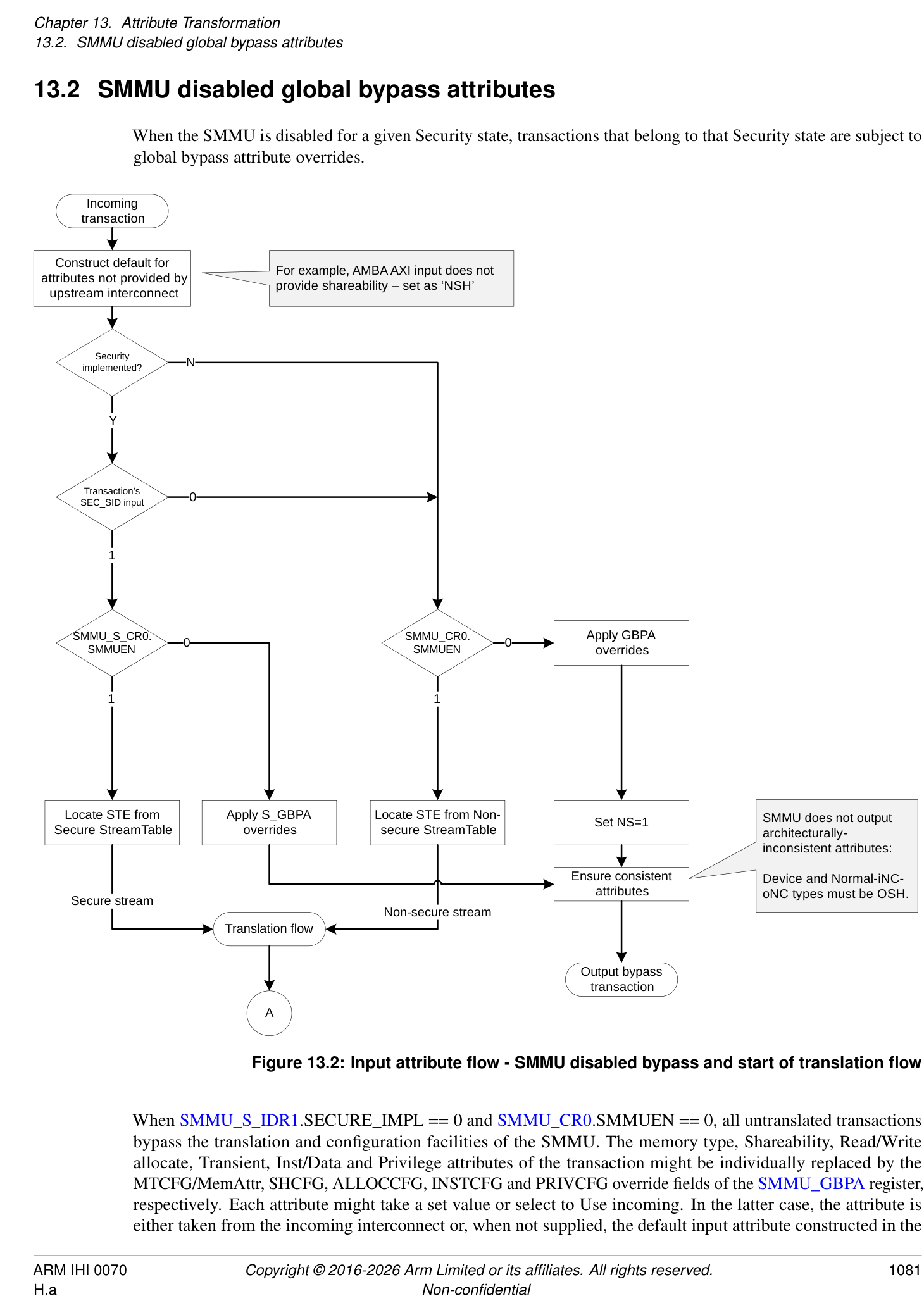
When SMMU_S_IDR1.SECURE_IMPL == 0 and SMMU_CR0.SMMUEN == 0, all untranslated transactions bypass the translation and configuration facilities of the SMMU. The memory type, Shareability, Read/Write allocate, Transient, Inst/Data and Privilege attributes of the transaction might be individually replaced by the MTCFG/MemAttr, SHCFG, ALLOCCFG, INSTCFG and PRIVCFG override fields of the SMMU_GBPA register, respectively. Each attribute might take a set value or select to Use incoming. In the latter case, the attribute is either taken from the incoming interconnect or, when not supplied, the default input attribute constructed in the
SMMU. Apart from these overrides, the transaction is output directly. For some classes of transaction, for example Cache Maintenance Operations, the SMMU may apply protocol-specific normalization on the output transaction attributes.
Note: When the SMMU is disabled, ATS Translation Requests and ATS-translated transactions are terminated by the SMMU. See section 3.9.1.2 Responses to ATS Translation Requests .
Alternatively, when SMMU_S_IDR1.SECURE_IMPL == 0 and SMMU_CR0.SMMUEN == 1, an STE is located and the translation flow begins.
When SMMU_S_IDR1.SECURE_IMPL == 1, the behavior of a transaction on arrival at the SMMU is determined by the Security state of its StreamID, as determined by the SEC_SID input, see section 3.10.1 StreamID Security state (SEC_SID) . If the stream is Non-secure and SMMU_CR0.SMMUEN == 0, the attributes are overridden by SMMU_GBPA as described earlier in this section. If the stream is Secure and SMMU_S_CR0.SMMUEN == 0, the attributes are determined by SMMU_S_GBPA in the same way, otherwise a Secure STE is located and the translation flow begins. The output NS attribute is determined by SMMU_S_GBPA.NSCFG, it can use the incoming value or be overridden to either state.
The reset state of the bypass attribute register SMMU_GBPA, and when SMMU_S_IDR1.SECURE_IMPL == 1 SMMU_S_GBPA, is IMPLEMENTATION DEFINED.
Note: The SMMU might provide an implementation-time configuration of the default bypass attributes which allows a system designer to ensure that device DMA has useful attributes even if system software has not initialized the SMMU.
Arm recommends that the default attributes are set as appropriate for the system in accordance with relevant base system architecture definitions.
This case is illustrated by this pseudocode:
// See 13.1.3: Attrs input_attrs = add_defaults_for_unsupplied(upstream_attrs); bool secure = (SEC_SID == SEC_SID_Secure); if (secure) { output_attrs = replace_attrs(SMMU_S_GBPA, input_attrs); } else { output_attrs = replace_attrs(SMMU_GBPA, input_attrs); output_attrs.NS = 1; } // MT, SH, RA, WA, TR, INST, PRIV are unchanged or overridden, // depending on respective register field. // // NS is unchanged or overridden if secure stream, otherwise // fixed at 1. // See 13.1.7: output_attrs = ensure_consistent_attrs(output_attrs);
13.3 Translation flow, STE bypasses stage 1 and stage 2
A second type of SMMU bypass is available when the SMMU is enabled. This is when a StreamID selects an STE configured to bypass (STE.Config == 0b100). SMMU_GBPA and SMMU_S_GBPA are not used, and a finer-grained per-STE configuration is available. Refer to the no-translate case of Figure 13.3.
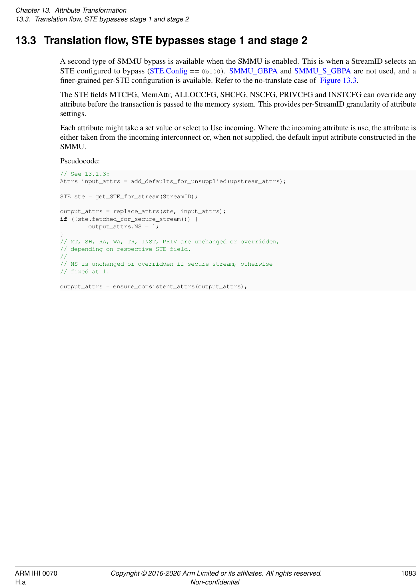
The STE fields MTCFG, MemAttr, ALLOCCFG, SHCFG, NSCFG, PRIVCFG and INSTCFG can override any attribute before the transaction is passed to the memory system. This provides per-StreamID granularity of attribute settings.
Each attribute might take a set value or select to Use incoming. Where the incoming attribute is use, the attribute is either taken from the incoming interconnect or, when not supplied, the default input attribute constructed in the SMMU.
Pseudocode:
// See 13.1.3: Attrs input_attrs = add_defaults_for_unsupplied(upstream_attrs);
STE ste = get_STE_for_stream(StreamID); output_attrs = replace_attrs(ste, input_attrs); if (!ste.fetched_for_secure_stream()) { output_attrs.NS = 1; } // MT, SH, RA, WA, TR, INST, PRIV are unchanged or overridden, // depending on respective STE field. // // NS is unchanged or overridden if secure stream, otherwise // fixed at 1.
output_attrs = ensure_consistent_attrs(output_attrs);
13.4 Normal translation flow
(From previous chart)
A
Apply STE overrides for
PRIV, INST, NS perms
Apply STE overrides for CD.MTOp
MT, SH, RA, WA, TR attrs
Y
0 1
STE: Stage1
translates?
MT replaced with values MT combined with values
from S1 translation from S1 translation
N
descriptor/MAIR attributes descriptor/MAIR attributes
SH replaced with values from
S1 translation descriptor/MAIR
attributes
RA, WA, TR combined with
values from S1 translation
descriptor/MAIR attributes
Check R/W, PRIV, INST
against page permissions
Secure stream or
Set NS from descriptor.NS and Realm EL2/EL2&0
intermediate NSTable flags only
Select S2 translation Secure stream only
STE: Stage2 Y table from S1 NS
translates?
output
Note: If input to S2 is Normal-NC
or stronger, but FWB forces WB,
MT, SH combined with then RA, WA are set to no-
N S2 translation allocate, otherwise RA, WA, TR
descriptor attrs are unmodified.
Note: PRIV is not checked in
Check R/W, PRIV, INST
SMMUv3.0 or in
against page
implementations where
permissions
SMMU_IDR3.XNX==0
For Non-secure stream, set NS=1.
For Secure stream, set NS from stage 2 translation table
configuration.
Ensure consistent For Realm stream, set NS from stage 2 translation table descriptor.
attributes
SH made consistent with MT
Output attributes
Figure 13.3: Attribute determination in translation
When the StreamID of a transaction selects an STE configuration with two stages of translation, the memory attribute of the transaction is determined by the stage 1 AttrIndex descriptor attribute and the MAIR fields, and combined with the stage 2 MemAttr descriptor attribute.
For stage 1-only translations, all of the following are true:
-
If SMMU_IDR3.MTCOMB is 0, the memory attributes are determined solely by the stage 1 descriptor attributes.
-
If SMMU_IDR3.MTCOMB is 1, the input memory type can be configured to combine with the stage 1 descriptor memory type.
For stage 2-only translations, the memory attributes are determined by the input attribute, with STE overrides, combined with the stage 2 descriptor attributes.
First, the incoming attributes, with defaults constructed for any unsupplied attributes, are subject to the STE override described in section 13.3 Translation flow, STE bypasses stage 1 and stage 2 . These attributes are provided to the first enabled stage of translation. If stage 1 bypasses, these attributes are provided to stage 2 directly.
If stage 1 translates, then all of the following are true:
-
If SMMU_IDR3.MTCOMB is 0, the stage 1 attributes are determined by the stage 1 descriptor in combination with the MAIR fields of the CD.
-
If SMMU_IDR3.MTCOMB is 1, the stage 1 attributes are determined by the stage 1 descriptor in combination with the input memory type.
Page permissions are determined by the stage 1 descriptor, in combination with fields of the CD.
The R/W, PRIV and INST attributes, as modified by STE overrides, are checked against the page permissions.
13.4.1 Stage 1 page permissions
When using the Direct Permission Scheme for stage 1, the effect of the lower bit of the stage 1 descriptor AP[2:1] field, AP[1], changes depending on the translation regime under which the translation is performed, as determined by StreamWorld. For EL1 or for any-EL2-E2H, the AP[1] bit controls the EL0 access permissions of the page (PRIV == 0). However, when StreamWorld == any-EL2 or StreamWorld == EL3, the AP[1] bit is ignored and treated as if it were 1. This has the same effect as treating PRIV == 1 for the purposes of permission checking, which means that input PRIV attributes and any STE.PRIVCFG overrides are ignored for these checks.
When PRIV and INST attributes are output to the memory system, they are presented as the result of applying the STE.PRIVCFG and STE.INSTCFG overrides to the input attribute. They are not modified after this point.
See section 3.26.1 Stage 1 permission indirections for when stage 1 is configured to use the Indirect Permission Scheme.
13.4.2 Stage 1 memory attributes
For the attributes determined from the stage 1 translation table descriptor and CD.MAIR, all of the following are true:
-
If SMMU_IDR3.MTCOMB is 0, they are provided directly to the stage 2 translation. The incoming attributes, including any STE overrides, are discarded and replaced by the stage 1 attributes, with the exception of RA/WA/TR.
-
If SMMU_IDR3.MTCOMB is 1, they are subject to CD.MTOp which can be configured to combine or replace the incoming memory type, including any STE overrides, before being provided to the stage 2 translation.
When the translation is from a Secure StreamID, the target IPA or PA space from stage 1 is determined directly from the effective NS bit of the descriptor, which must take into account the value of NSTable flags on intermediate Table descriptors in addition to the final descriptor NS flag, in the same way as on the PE. In addition, CDs that are used with Secure streams contain NSCFGx flags that determine the starting NS attribute of translation table walks
performed through CD.TTB0/1. When a translation is fetched using a CD.TTB0/1 with a corresponding NSCFGx == 1, the stage 1 targets Non-secure IPA or PA space. When a translation is from a Non-secure stream, the output NS attribute that is output is always 1 and the NS attribute that was input with the transactions is ignored.
When Secure stage 2 is supported and enabled, the final transaction NS bit depends on the configuration of the stage 2 IPA space, STE.{S2NSA, S2NSW, S2SA, S2SW}. See section 3.10.2.2 Secure EL2 and support for Secure stage 2 translation . Otherwise, the final transaction uses the target IPA space from stage 1, or stage 1 bypass.
Note: The behavior of the input NS attribute in a stage 1-only configuration matches the SMMUv2 [4] behavior in that the input NS attribute is wholly determined by the stage 1 descriptor and translation table walk configuration. The input NS attribute and STE override only affect the target IPA or PA space when no stage 1 translation is configured.
When the attribute input to stage 1 is a Normal-cacheable type, the RA/WA/TR attributes are not discarded and instead are combined with those determined from the stage 1 translation descriptor and CD.MAIR. Any other type does not communicate RA/WA/TR hints, in which case the stage 1 translation RA/WA/TR attributes are used directly.
If SMMU_IDR3.MTCOMB is 1, the SMMU can be configured to combine the the incoming memory type, including any STE overrides. If the memory type after applying CD.MTOp is not Normal-cacheable type, then the RA/WA/TR hints are not communicated.
All other attributes are overridden by stage 1 translation table attributes.
Note: This property, combined with STE.ALLOCCFG == 0b0xxx configuration, allows a client device to influence per-transaction allocation/transient attributes when using stage 1 translation tables, allowing sub-page control.
13.4.3 Stage 2
If stage 2 bypasses, the attributes provided by the incoming transaction or the stage 1 translation are forwarded unchanged to the memory system.
If stage 2 translates, the MT and SH attributes input to stage 2 undergo a combine operation with the stage 2 translation descriptor attributes to produce the output attributes. If STE.S2FWB == 1, then the combine operation uses the encoding and behavior of the stage 2 translation descriptor attributes for the FWB feature as described in Armv8.4 [2].
If stage 2 translates, then for each cacheability domain where the final memory type is any Normal cacheable type, all of the following apply:
-
If the input to stage 2 specifies any Normal cacheable memory type, then the final cache allocation hints are the stage 2 input cache allocation hints.
-
If the input to stage 2 does not specify any Normal cacheable memory type, then the final cache allocation hints are as follows:
-
If SMMU_IDR3.MTCOMB is 1: Read No-Allocate, Write No-Allocate.
-
If SMMU_IDR3.MTCOMB is 0: Read-Allocate, Write-Allocate, Non-transient.
-
Note: This includes the following cases:
-
CD.MTOp is 0 and the memory type defined by stage 1 descriptor is Normal-NC or any-Device.
-
CD.MTOp is 1 and the incoming memory type after applying STE.MemAttr is Normal-NC or any-Device.
-
STE.EATS is 0b10 (Split-stage ATS) and the incoming memory type of a Translated transaction is Normal-NC or any-Device.
The INST attribute is checked, along with R/W, to evaluate stage 2 permissions. If SMMU_IDR3.XNX == 0, the PRIV attribute is not used to evaluate stage 2 permissions. If SMMU_IDR3.XNX == 1, the PRIV attribute is used to evaluate stage 2 permissions.
When using the Direct Permission Scheme, stage 2 checks are performed against the descriptor page permissions.
See section 3.26.2 Stage 2 permission indirections for when stage 2 is configured to use the Indirect Permission Scheme.
13.4.4 Output
The transaction is output after ensuring consistency of the attributes and forcing NS == 1 for transactions on Non-secure streams.
Pseudocode, which also illustrates the cases describe in sections 13.2 SMMU disabled global bypass attributes and 13.3 Translation flow, STE bypasses stage 1 and stage 2 in more detail, is show below:
// See 13.1.3:
Attrs input_attrs = add_defaults_for_unsupplied(upstream_attrs);
bool secure = (SEC_SID == SEC_SID_Secure);
if (secure && SMMU_S_CR0.SMMUEN == 0) {
output_attrs = replace_attrs(SMMU_S_GBPA, input_attrs); // See 13.1.7: output_attrs = ensure_consistent_attrs(output_attrs); output_transaction(output_attrs); // Address, direction not shown // Done.
} // Else carry on below
if (!secure && SMMU_CR0.SMMUEN == 0) {
output_attrs = replace_attrs(SMMU_GBPA, input_attrs); output_attrs.NS = 1; // See 13.1.7: output_attrs = ensure_consistent_attrs(output_attrs); output_transaction(output_attrs); // Address, direction not shown // Done.
} // Else carry on below
// If we get to here, the appropriate SMMU interface is enabled and
// configuration can be fetched: STE ste = get_STE_for_stream(StreamID);
Attrs i;
// Starting attributes are as input, with STE overrides: i = replace_attrs(ste, input_attrs);
if (ste.s1_translates()) { Attrs s1_attrs; TTD s1_ttd;
CD cd = get_CD(ste, StreamID, SubstreamID, SubstreamID_valid);
s1_ttd = s1_translation(cd, ste); // Address not shown; IPA determined from VA. NS of stage 1 translation // table walk depends on CD.NSCONFIGx and is not shown here.
s1_attrs = s1_ttd.lookup_attrs(); // The returned s1_attrs contains attributes determined from the // translation descriptor and MAIR, including RA/WA and TR.
if (s1_ttd.translation_fault()) { // XXXX Stage 1 translation fault // Note: A speculative read transaction is simply terminated // with abort here, without recording an event. } // Note: Permission checking must consider HTTU configuration, // and update Access flag and Dirty state instead of signaling a related fault // when HTTU enabled: if (check_perms_and_httu(cd, s1_ttd, i.RW, i.INST, i.PRIV) == FAULT) { // XXXX Stage 1 permissions or Access flag fault // Note: EL2 or AArch64 EL3 stage 1 do not check PRIV, // i.e. client traffic behaves as if PRIV == 1. However, // the PRIV attribute is not modified.
} // Note: See section 13.4.2; when a cached type is input to Stage 1, // s1_attrs.{RA,WA,TR} are combined with i.{RA,WA,TR} instead of // replacement (non-cached/Device types do not express RA/WA/TR // attributes): if (is_cached_type(i.MT)) { i.{RA,WA,TR} = combine_attrs(i.{RA,WA,TR}, s1_attrs.{RA,WA,TR}); } else { // An input NC/Device type does not provide these attributes, // so take these attributes from S1: i.{RA,WA,TR} = s1_attrs.{RA,WA,TR}; } // If CD.MTOp is configured to combine, the Stage 1 MT is combined with // the incoming MT. Otherwise MT is taken directly from Stage 1. // SH is always taken directly from Stage 1: if CD.MTOp == 1 { i.MT = combine_attrs(s1_attrs.MT, i.MT); } else { i.MT = s1_attrs.MT; } i.SH = s1_attrs.SH // NS is taken from the ‘effective’ value calculated from // S1 Block or Page descriptor, CD.NSCONFIGx and appropriate NSTable bits: i.NS = s1_ttd.get_effective_NS();
// RW, INST, PRIV do not change. } else { // MT, SH, RA, WA, TR unchanged; and RW, INST, PRIV, NS // permissions passed through. }
if (ste.s2_translates()) { Attrs s2_attrs; TTD s2_ttd; // Fetch stage 2 translation table descriptor. // Address not shown; PA determined from IPA and HTTU is performed. if (secure) { // Perform S-IPA or NS-IPA translation table walk with given NS: bool sipa_s2_ttw_ns = ste.S2SW; bool nsipa_s2_ttw_ns = ste.S2NSW; // Final NS is a function of the walk NS: bool sipa_ns = sipa_s2_ttw_ns || ste.S2SA; bool nsipa_ns = nsipa_s2_ttw_ns || sipa_ns || ste.S2NSA; // The NS input to stage 2 indicates the NS or S IPA space. if (i.NS) { s2_ttd = s2_translation_ns_ipa(ste, nsipa_s2_ttw_ns); i.NS = nsipa_ns; } else { s2_ttd = s2_translation_s_ipa(ste, sipa_s2_ttw_ns); i.NS = sipa_ns; } } else { // Non-secure stream s2_ttd = s2_translation(ste); } s2_attrs = s2_ttd.lookup_attrs(); if (s2_ttd.translation_fault()) { // XXX Stage 2 translation fault // Note: On any fault, a speculative read transaction is simply // terminated with abort.
// Note: HTTU at Stage 1 is permitted, even if we fault @S2
}
// S2 does not encode RA/WA/TR; these values plus combine_attrs() below // result in “take input from S1/previous step” behavior for RA/WA/TR: s2_attrs.RA_inner = true; s2_attrs.RA_outer = true; s2_attrs.WA_inner = true; s2_attrs.WA_outer = true; s2_attrs.TR_inner = false; s2_attrs.TR_outer = false;
if (s2_ttd.S2FWB == 0) { // MT, SH, RA, WA, TR updated via combine: i = combine_attrs(i, s2_attrs);
} else { // combine_attrs_fwb() treats the encoding of stage 2 // attribues as defined for the FWB features in Armv8.4 i = combine_attrs_fwb(i, s2_attrs);
}
// See HTTU note in Stage 1: if (check_perms_and_httu(ste, s2_ttd, i.RW, i.INST, i.PRIV) == FAULT) { // XXXX Stage 2 permissions or Access flag fault
// Note: S2 checks PRIV if SMMU_IDR3.XNX == 1. } } else { // MT, SH, RA, WA, TR unchanged; and RW, INST, PRIV, NS // permissions passed through. }
// Finally, a Non-secure stream is not permitted to output NS == 0;
// the overrides and page attribute are ignored: if (!secure) { output_attrs.NS = 1; } // MT, SH, RA, WA, TR may be modified by translations and overrides. // INST, PRIV may be modified by STE overrides. //
// For a secure stream, stage 1 output NS is determined from the Stage 1 // translation (if present), otherwise is the STE override or input value. // This is used to select an IPA space in stage 2, or output directly if no // stage 2.
// See 13.1.7: output_attrs = ensure_consistent_attrs(output_attrs);
output_transaction(output_attrs); // Address, direction not shown // Done.
13.5 Summary of attribute/permission configuration fields
The attributes output from the SMMU are determined as follows.
| If translation occurs | If translation occurs | If translation occurs | If bypass | If bypass | |
|---|---|---|---|---|---|
| Attribute | Stage 1-only | Stage 1 + stage 2 | Stage 2-only | SMMUEN == 1 butSTE.Confg== 0b100 | SMMUEN == 0 |
| INST | Data, if required by the memory system. | ||||
| PRIV | Privileged, if required by the memory system. | ||||
| PA space (Secure stream) | Effective S1_TTD.NS, NSTable and CD.NSCFGx | Effective S1_TTD.NS, NSTable CD.NSCFGxand STE.{S2NSA, S2NSW, S2SA S2SW} | STE.NSCFGand STE.{S2NSA, S2NSW, S2SA S2SW} | STE.NSCFG | SMMU_S_GBPA .NSCFG |
| PA space (Realm stream) | EL1: Fixed, Realm PA space. EL2 or EL2-E2H: S1_TTD.NS | S2_TTD.NS | S2_TTD.NS | STE.NSCFG | Transaction aborted |
| PA space (Non- secure stream) | Fixed, Non-secure PA space | ||||
| MT | Combine(STE. {MemAttr, MTCFG}, CD.MAIR[ S1_TTD.AttrIndx], CD.MTOp) | Combine(STE. {MemAttr, MTCFG}, CD.MAIR[ S1_TTD.AttrIndx], S2_TTD.MemAttr, STE.S2FWB, CD.MTOp) | Combine(STE. {MemAttr, MTCFG}, S2_TTD.MemAttr, STE.S2FWB) | STE. {MemAttr, MTCFG} | SMMU_(S_) GBPA. {MemAttr, MTCFG} |
| RA, WA, TR | CD.MAIR[ S1_TTD.AttrIndx], if STE.{MemAttr, MTCFG} provide any-Device or NC input to Stage 1, otherwise: Combine( STE.ALLOCCFG, CD.MAIR[ S1_TTD.AttrIndx]) | CD.MAIR[ S1_TTD.AttrIndx], if STE.{MemAttr, MTCFG} provide any-Device or NC input to Stage 1, otherwise: Combine( STE.ALLOCCFG, CD.MAIR[ S1_TTD.AttrIndx]) | Combine( STE.ALLOCCFG, S2_TTD.MemAttr) | STE.ALLOCCFG | SMMU_(S_) GBPA. ALLOCCFG |
| If translation occurs | If bypass | |
|---|---|---|
| Attribute Stage 1-only Stage 1 + stage 2 Stage 2-only SMMUEN == 1 butSTE.Confg== 0b100 SMMUEN == 0 | ||
| SH S1_TTD.SH Combine ( S1_TTD.SH, S2_TTD.SH) Combine ( STE.SHCFG S2_TTD.SH) STE.SHCFG SMMU_(S_) GBPA.SHCFG |
Notes:
-
Permission checking of InD and PnU against translation descriptor fields is not shown here.
-
References to INSTCFG, PRIVCFG, NSCFG, MTCFG/MemAttr and ALLOCCFG refer to the effective output of these override fields, which might always be the incoming attribute depending on SMMU_IDR1.ATTR_PERMS_OVR and SMMU_IDR1.ATTR_TYPES_OVR. This table does not show the effect of one field on another field. For example, the configuration used to determine allocation/transient hints or Shareability is irrelevant if the MemType is of any-Device type. See section 16.7.5 SMMU and AMBA attribute differences for other interconnect-specific dependencies between attributes.
-
(a): If stage 2 translation is enabled, and STE.S2FWB==1, the Combine() operation for memory is instead an override operation for some values of the stage 2 MemAttr field.
13.6 PCIe and ATS attribute/permissions handling
This section covers an area of system architecture that intersects with the SMMU operation. Integration of PCIe, particularly with ATS, requires consideration of the presentation of transactions to the SMMU from the Root Complex and the overall system architecture, including platform definitions such as the Base System Architecture [12] and Server Base System Architecture [13], in addition to that of the SMMU itself.
In many systems it will be typical to have a discrete Root Complex IP block connected to a downstream SMMU IP block by a standard piece of interconnect fabric, for example using AXI. This section considers the attributes provided to the SMMU by the Root Complex on such an upstream interconnect in relation to the output attributes provided by the SMMU downstream into the system.
Note: An ATS client makes a Translation Request to the SMMU and caches the resulting Physical Address in its local Address Translation Cache (PCIe terminology for a remote TLB). When a client has successfully received a translation, it might use it later to make direct physically-addressed (Translated) accesses to the page, which are intended to bypass SMMU translation altogether. However, the PCIe [1] ATS protocol does not explicitly provide a field to convey a memory type/access attribute to the client in the completion of the Translation Request. Therefore, the subsequent Translated transaction is issued from the endpoint with no attributes (beyond R/W) unless ATS attributes are supported.
13.6.1 PCIe memory type attributes
PCIe does not contain memory type attributes, and each transaction takes a system-defined memory type when it progresses into the system. The Base System Architecture [12] requires the intial memory type to be Normal cacheable shareable (IO-coherent) before No_snoop transformations are taken into account.
Note: When PCIe is used with an SMMU, the SMMU can assign a different attribute if necessary, but the common usage model is for PCIe DMA to remain Normal cacheable shareable and the SMMU is primarily used for address transformation/protection rather than attribute assignment.
Note: The Base System Architecture [12] requires that, when no SMMU is present or an SMMU is present and in global or stream bypass mode, a transaction from a Root Complex targeted at memory is presented to the memory system with a fixed attribute of Normal cacheable shareable. The exact attribute will be Normal-iWB-oWB-ISH or OSH and is system-dependent, but is considered fixed/static because PCIe does not encode different memory types. The system must treat transactions that are targeted at devices (such as MSIs) as Device type accesses.
The incoming attributes of Untranslated transactions forwarded to the SMMU by the Root Complex are as follows:
-
If SMMU_IDR3.MTCOMB is 0, Untranslated transactions have the fixed Normal cacheable shareable attribute.
-
If SMMU_IDR3.MTCOMB is 1, Untranslated transactions have either:
-
The Normal cacheable shareable attribute.
-
The Normal non-cacheable attribute.
-
When an SMMU is used with translation (i.e., not in bypass mode), the SMMU might be configured to use Stage 1/Stage 2 translation and/or STE input overrides, determining an output attribute from a function of the input, translation table descriptor and override attributes as described previously in this chapter. The final attribute is defined by software configuration.
Note: See No_snoop below, which might alter the final output attribute if SMMU_IDR3.MTCOMB is 0.
If SMMU_IDR3.MTCOMB is 0, it is IMPLEMENTATION DEFINED whether attribute overrides affect streams associated with PCIe devices or whether the incoming attribute is used. See:
-
STE.MTCFG.
-
STE.ALLOCCFG.
-
STE.SHCFG.
-
SMMU_GBPA.MTCFG.
-
SMMU_GBPA.ALLOCCFG.
-
SMMU_GBPA.SHCFG.
13.6.1.1 No_snoop
Note: In PCIe, No_snoop is not guaranteed to be supported by a device or Root Complex, and if it is supported by a device, it might be disabled via configuration space. When a transaction includes a No_snoop == 1 flag, it indicates that the transaction is allowed to “opt-out” of hardware cache coherency; software cache coherency ensures the access would not hit in a cache, so the I/O access is permitted to avoid snooping caches.
In an Arm system, a No_snoop access corresponds to Normal-iNC-oNC-OSH.
Support for No_snoop is system-dependent. If No_snoop is supported, then the way in which No_snoop interacts with the SMMU is dependent on the value of SMMU_IDR3.MTCOMB.
If SMMU_IDR3.MTCOMB is 0 then all of the following apply:
-
No_snoop transforms a final access attribute of a Normal cacheable type to Normal-iNC-oNC-OSH downstream of (or appearing to be performed downstream of) the SMMU. No_snoop does not transform a final access attribute of any-Device.
-
No_snoop applies after the application of the STE.S2FWB bit.
Note: To achieve this “pull-down” behavior, the No_snoop flag might be carried through the SMMU and used to transform the SMMU output downstream.
If SMMU_IDR3.MTCOMB is 1 then all of the following apply:
-
The SMMU does not transform the memory type based on the No_snoop attribute. Instead, No_snoop is applied on the incoming memory attributes as specified in the Arm Base System Architecture [12].
-
Software should configure CD.MTOp to combine, such that the SMMU permits the effect of No_snoop to propagate to the memory system downstream of the SMMU.
-
Transactions are still subject to stage 2 and DPT controls, if enabled. This means that if a transaction is Forced-WB, then the PCIe No_snoop attribute does not affect the output memory type regardless of the value of CD.MTOp.
13.6.2 ATS attributes overview
The SMMU determines the output attributes of Untranslated transactions from a function of input, input overrides and translation tables. Therefore, the output attributes are address-dependent.
When an ATS Translated transaction is forwarded to the SMMU, it may bypass address translation depending on the value of STE.EATS.
The memory attributes of an ATS Translated transaction before the effects of No_snoop are applied are an IMPLEMENTATION DEFINED choice of one of the following:
-
Normal cacheable shareable.
-
Memory attributes consistent with those that would result from an Untranslated transaction to the same address. This can result from using ATS attributes.
Note: For example, ATS attributes might be supported by leveraging the PCIe AMA field to assign Arm-specific attributes to ATS Translated transactions.
Note: If ATS attributes are not supported, the resulting output attributes of an ATS Translated transaction may differ from those of a non-ATS/Untranslated access to the same address. This is acceptable in systems where such a mismatch does not compromise correctness.
If SMMU_IDR3.MTCOMB is 0, and ATS attributes are supported by the SMMU, the SMMU modifies the attributes of the transaction as appropriate for the accessed page.
If SMMU_IDR3.MTCOMB is 1, the SMMU expects ATS attributes to be applied at the input to the SMMU, and that the effect of No_snoop is additionally applied to the attributes of ATS Translated transactions before they are presented to the SMMU. These attributes are still subject to stage 2 and DPT controls, if enabled.
Note: Where No_snoop is applied, ATS Translated transaction input memory attributes are Normal non-cacheable.
If SMMU_IDR3.MTCOMB is 1, and the SMMU supports encoding memory attributes into ATS Translation Completions, Arm recommends that the SMMU also encodes the value of the output allocation hints. This enables devices to supply allocation hints for Translated transactions using ATS.
If SMMU_IDR3.MTCOMB is 1 and SMMU_(R_)CR0.ATSCHK is 1, then STE.ALLOCCFG applies to incoming memory attributes of Translated transactions in addition to Untranslated transactions.
Note: In versions of the SMMU architecture up to and including SMMUv3.3, an SMMU implementation might store translation-specific attributes in the otherwise unused, most significant bits of the physical address fields in ATS Translation Completions and ATS Translated transactions. This is referred to as Attribute stashing. In SMMUv3.3 implementations, if SMMU_ROOT_IDR0.REALM_IMPL == 1, the SMMU never performs Attribute stashing, and always returns zeros in the most significant bits of the physical address field above its implemented physical address size in ATS Translation Completions. From SMMUv3.4, Attribute stashing is forbidden.
13.6.2.1 Supporting No_snoop with ATS
If SMMU_IDR3.MTCOMB is 0, then all of the following apply:
-
If the SMMU supports the encoding of attributes into ATS, the mechanism for determining the ATS Translated attributes in the SMMU is independent of the subsequent application of a No_snoop non-cacheable/downgraded attribute.
-
The N field in ATS Translation Completions is always 0. The SMMU does not provide the means to control No_snoop per-page.
If SMMU_IDR3.MTCOMB is 1, then all of the following apply:
-
If the SMMU supports the encoding of attributes into ATS, then No_snoop is expected to be applied on attributes supplied with Translated transactions before being processed by the SMMU.
-
Arm recommends that the N field is set to 1 when any of the following apply:
-
The ATS Translation Request is Forced-WB.
-
The ATS Translation Request is subject to stage 1 and all of the following apply:
-
[CD.MTOp][ is configured to replace the incoming memory type.]
-
[The resultant memory type is Normal-iWB-oWB.]
-
-
13.6.3 Split-stage (STE.EATS == 0b10) ATS behavior and responses
When Split-stage ATS is enabled for a stream (that is, when STE.EATS == 0b10, SMMU_CR0.ATSCHK == 1 and STE.Config == 0b111), the response to an ATS Translation Request contains an IPA. When a Translated transaction is emitted as a result of this response, its IPA then undergoes stage 2 translation in the SMMU.
Note: In effect, the stage 1 VA to IPA translation is held in the ATC but stage 2 IPA to PA translation is still performed in the SMMU. This can be used to increase security/isolation over regular nested EATS == 0b01 ATS, where the system does not trust the endpoint to use physical addresses directly.
The behavior of Split-stage ATS is the same as regular EATS ==0b01 ATS with nested translation, except:
-
The completion contains the IPA result from the Stage 1 translation of the requested VA (instead of the output PA from stage 1+stage 2 translation of the requested VA).
-
If the SMMU supports the encoding of attributes into ATS (see section 13.6.2 ATS attributes overview ), an attribute is returned that gives a final output equivalent to the Stage 1+Stage 2 combined attribute when the resulting ATS Translated transaction is subject to stage 2 translation in the SMMU. This may be implemented in any of the following ways:
-
Returning a Stage 1 attribute that is later combined with stage 2 attributes.
-
Returning a Stage 1+2 combined attribute that is later combined again with stage 2 attributes (which gives the same result).
-
Returning a Stage 1+2 combined attribute that is not later combined with stage 2 attributes. This is permitted only if SMMU_IDR3.MTCOMB is 0.
-
-
HTTU might be performed by the stage 2 translation that occurs as part of the ATS Translation Request, or it might be performed at the time of the stage 2 translation for a subsequent Translated transaction.
All other aspects are identical to regular EATS == 0b01 ATS with nested translation:
-
Permissions are granted from the combination of the stage 1 and stage 2 translation permissions (see 13.7 PCIe permission attribute interpretation ), with respect to the permissions requested in the Translation Request.
-
The maximum permissible translation size is derived from the intersection of stage 1 and stage 2 page/block sizes. Arm recommends that, for performance reasons, the maximum translation size is returned where possible.
- Note: The largest translation size is the minimum of the stage 1 and stage 2 translation sizes for the given address, such that the returned translation represents a single span with constant permission and translation.
See 13.6.5 Split-stage ATS skipping stage 1 for behavior of STE.S1DSS skipping stage 1.
The behavior of an incoming Translated transaction differs depending on the EATS configuration of the StreamID presenting the transaction:
-
When EATS == 0b01, the Translated transaction is presented directly to the output. The given address is treated as a PA. The output attributes are one of the following:
-
If the SMMU supports the encoding of attributes into ATS: the attributes encoded in the translated transaction.
-
Otherwise: the Normal cacheable shareable attribute.
-
Note: In both cases, if SMMU_IDR3.MTCOMB is 0 the SMMU transforms the output attributes based on No_snoop. If SMMU_IDR3.MTCOMB is 1, the effect of No_snoop (if present) is expected to be applied before transactions are processed by the SMMU. Therefore, the output attribute can be Normal non-cacheable.
-
When EATS == 0b10, the Translated transaction provides an IPA. The output attributes are one of the following:
-
If the SMMU supports encoding of attributes into ATS: the attributes in the Translated transaction combined with stage 2 attributes. Note: This might be implemented as returning a Stage 1+2 combined attribute in the ATS Translation Completion, and the attributes supplied with the Translated transaction are then passed through and do not later combine with stage 2 attributes. This is permitted only if SMMU_IDR3.MTCOMB is 0.
-
If the SMMU does not support encoding of attributes into ATS: Normal cacheable shareable combined with stage 2 attributes.
-
Note: In both cases, if SMMU_IDR3.MTCOMB is 0 the SMMU transforms the output attributes based on No_snoop. If SMMU_IDR3.MTCOMB is 1, the effect of No_snoop (if present) is expected to be applied before the transaction is processed by the SMMU (before being combined with stage 2 attributes).
The behavior for permission attributes overrides on ATS Translated transactions is described in 13.7 PCIe permission attribute interpretation .
EATS == 0b10 configuration is only usable when SMMU_CR0.ATSCHK == 1.
Note: ATSCHK == 1 causes Translated transactions to look up and be checked against STE configuration, which for EATS == 0b10 provides the stage 2 with which to translate and for EATS == 0b01 allows the transaction to bypass without translation.
13.6.4 Full ATS skipping stage 1
When all of the following are true, transactions arriving without a PASID are configured to skip stage 1 translation:
STE.Config == 0b1x1 (Stage 1 translation enabled) STE.EATS == 0b01 (“Full ATS” enabled)
| STE.S1CDMax!= 0 | (Substreams/PASIDs enabled) |
|---|---|
| STE.S1DSS== 0b01 | (non-PASID transactions bypass Stage 1) |
If stage 2 translation is enabled (STE.Config == 0b11x), an ATS Translation Request without a PASID is translated stage 2-only as though STE.Config[1:0] == 0b10. The Translation Completion returns a PA from the stage 2-only translation.
Where a stage 1 + stage 2 configuration has the first stage skipped due to STE.S1DSS == 0b01, the translation process behaves as though stage 1 were not configured (corresponding to STE.Config == 0b1x0). If ATS attributes are supported, the final attribute is therefore determined by the upstream input attribute (if provided), replaced by STE overrides where configured, and combined with the attribute from the stage 2 translation table descriptor.
If stage 2 is not enabled, an ATS Translation Request without a PASID made to this configuration skips the single translation stage and, if a fault or configuration error has not occurred, its Translation Completion returns a direct-mapped “pass-through” of the stage. Responses to requests that lead to faults and configuration errors are described in section 3.9.1.2 Responses to ATS Translation Requests .
This is encoded as an identity-mapped Translation Completion containing:
-
U == 0
-
R == 1
-
W == 1
-
TranslatedAddress 1:1/identity-mapped with the Untranslated Address provided in the Translation request.
-
Translation size containing at least the requested Untranslated Address
-
Note: An implementation might return a larger identity-mapped region, as any address accessed under the same StreamID/configuration conditions will result in this type of response. A larger region might avoid future page-by-page translation requests.
-
The maximum permissible translation size is the same as the OAS (see section 3.4 Address sizes ).
-
-
Note: As this response is made for an ATS Translation Request received without a PASID, the request cannot contain Execute_Requested == 1 or Privileged_Mode_Requested == 1 as these fields are carried in a PASID. The response is made with Execute_Permitted and Privileged_Mode_Access both 0.
-
Note: This response causes the function to make 1:1 accesses to physical addresses, equivalent to the behavior of untranslated non-ATS transactions from the same stream.
The output attribute is a function of the upstream input attribute (if provided), replaced by STE overrides (where configured); this can be evaluated at the time of the Translation Request and encoded into the returned Translated Address as per section 13.6.2 ATS attributes overview .
13.6.5 Split-stage ATS skipping stage 1
Where all of the following are true, a Translation Request without a PASID is configured to skip stage 1 translation, but the ATS configuration is for stage 1-only:
-
STE.Config[1:0] == 0b11 (Stage 1 and 2 translation enabled)
-
STE.EATS == 0b10 (Split-stage ATS enabled)
-
STE.S1CDMax > 0 (Substreams/PASIDs enabled)
-
STE.S1DSS == 0b01, (non-PASID transactions bypass stage 1)
The Translation Request might lead to a fault or configuration error that triggers an ATS response as described in section 3.9.1.2 Responses to ATS Translation Requests .
Note: Even if stage 1 is effectively bypassed, a stage 1 Address Size Fault might occur if the input address supplied in the Translation Request is greater than the IAS.
Note: A Permission fault leads to one or more of R, W and X permissions being denied in the response, as shown in the next paragraph.
Where a Translation Request with a Split-stage ATS configuration skips stage 1, the Translation Request supplies an IPA address and, if a fault or configuration error does not occur, an identity-mapped Translation Completion is returned, which contains:
-
U == 0
-
R and W permissions are granted from the stage 2 permissions for the IPA, with respect to the permissions requested in the Translation Request.
-
TranslatedAddress 1:1/identity-mapped with the Unstranslated Address of the Translation request.
-
The maximum permissible translation size is that of the stage 2 translation. Arm recommends that, for performance reasons, the maximum translation size is returned where possible.
-
Note: See 13.6.4 Full ATS skipping stage 1 ; this response is made with Execute_Permitted and Privileged_Mode_Access both 0 as it is in response to a request made without a PASID.
If the SMMU supports the encoding of attributes into ATS (see 13.6.2 ATS attributes overview ), an attribute is returned that causes the resulting ATS Translated transaction to have a final output (after Stage 2 translation in the SMMU) equivalent to the upstream input attribute (if provided), replaced by STE overrides (where configured), combined with the attributes configured in Stage 2 translation. This does not account for the effect of No_snoop, see section 13.6.2.1 Supporting No_snoop with ATS .
Note: If SMMU_IDR3.MTCOMB is 1, then the ATS attributes supplied with a Translated transaction are always Combined with Stage 2 attributes.
The function then performs Translated accesses with IPAs and these are translated stage 2-only in the same way as described above for Split-stage ATS that does not skip stage 1.
13.7 PCIe permission attribute interpretation
PCIe-domain permissions are interpreted by the SMMU as described in this section.
Base PCIe interconnect expresses only a Read/Write access permission. The PASID TLP prefix adds the following access permissions:
-
Execute (In the PASID, Execute_Requested, hereafter referred to as ‘Exe’)
-
Privileged (In the PASID, Privileged_Mode_Requested, hereafter referred to as ‘Priv’)
For normal transactions, the SMMU can use R/W and Privileged directly as incoming R/W and PRIV attributes. Note: The PASID TLP prefix can only encode an ‘Execute’ attribute for Memory Read Requests; this is compatible with the SMMU’s behavior in considering all write transactions to be Data.
The SMMU interprets the INST and PRIV attributes of a normal transaction without a PASID TLP prefix as “Data” and “Unprivileged”, respectively.
For an ATS Translation Request, base PCIe supplies:
-
Read access is implied in all ATS Translation Requests
- An ATS Translation Completion might grant per-page Read access, depending on page permissions.
-
No-Write (NW)
-
NW == 0 signals the intention of the device to perform write accesses. When NW == 0, the Translation Completion sent by the SMMU grants Write permission if the page is currently marked as either:
-
[Writable-dirty.]
-
[Writable-clean if HTTU is enabled.]
-
When NW == 1, Write permission is permitted but not required to be granted if the page is already marked as writable-dirty.
-
If HTTU is not enabled, Write permission is not granted when the page is marked as writable-clean.
-
When HTTU is enabled, a request having NW == 0 to a page marked writable-clean updates the page to be marked Dirty and then grants Write permission in the response. See 3.13.7 ATS, PRI and translation table flag update .
-
Note: Referring to the above, a request with NW == 1 might grant write access if the page is already marked Dirty (as the page permissions contain write permission).
-
HTTU does not mark a page Dirty in response to a Translation Request with NW == 1.
-
The PASID TLP prefix adds the following to an ATS Translation Request:
-
Execute (Exe)
-
This flag requests execute permission. If this flag is set, the response might grant execute permission. The response must not grant execute permission if this flag is not set in the request. A valid translation might or might not grant the requested Execute permission, depending on actual page ‘X’ permission. Note: A request might be made with Exe == 1 and NW == 0, meaning an endpoint requests access for write and execute. This does not imply that the endpoint will perform ‘instruction writes’ to the page.
-
Exe implies R in an ATS response.
-
Certain configurations of VMSAv8-64 translation tables allow an ‘XO’ execute-only permission. A translation that requests Exe permission through ATS is not compatible with an XO page and will result in no access, unless STE.INSTCFG == Instruction. Similarly, care must be taken when using the Stage 2 ‘XO’ permission with ATS; a guest might map all executable pages as RX but a hypervisor Stage 2 can further modify this down to execute-only. See section 13.7.1 Permission attributes granted in ATS Translation Completions below for more information on ATS Exe permission.
-
Privileged (Priv)
-
This flag marks the request as being made from a privileged or unprivileged entity in the endpoint. The Priv flag in an ATS Translation Completion Data Entry has the same value as the Priv flag provided with the corresponding ATS Translation Request and the entry contains permissions granted only to that entity/privilege level.
Note: The PCIe Specification [1] states: “The ATC must not assume any correlation between the Privileged Mode and Unprivileged Mode permissions associated with a translation.”
For an ATS Translation Request without a PASID TLP prefix, the INST and PRIV attributes are treated by the SMMU as “Data” and “Unprivileged”, respectively.
Translated transactions that do not have a PASID TLP prefix are treated by the SMMU as “Data”, “Unprivileged”. This applies to all of the following:
-
Implementations with SMMU_IDR3.PASIDTT == 0.
-
Implementations with SMMU_IDR3.PASIDTT == 1, and the Translated transaction does not have a PASID TLP prefix.
The SMMU uses incoming Priv and Exe attributes if provided in the PASID TLP prefix if SMMU_IDR3.PASIDTT == 1.
The following table of example ATS Translation Requests shows the access permissions granted for the request on several different page permission combinations:
| Example Request | Page permissions | Response |
|---|---|---|
| NW == 1, Exe == 0, Priv == 0 | User-RO, Priv-RW, XN == 0 | R == 1, W == 0, Exe == 0, Priv == 0 |
| NW == 0, Exe == 0, Priv == 0 | User-RW, Priv-RW, XN == 0 | R == 1, W == 1, Exe == 0, Priv == 0 |
| NW == 0, Exe == 0, Priv == 0 | User-RO, Priv-RW, XN == 0 | R == 1, W == 0, Exe == 0, Priv == 0 |
| NW == 0, Exe == 0, Priv == 1 | User-RO, Priv-RW, XN == 0 | R == 1, W == 1, Exe == 0, Priv == 1 |
| NW == 1, Exe == 1, Priv == 0 | User-RW, Priv-RW, XN == 1 | R == 1, W == 0 or 1, Exe == 0, Priv == 0 |
| Note: The SMMU is permitted to return | ||
| Write permission if the page is writable, | ||
| even if NW == 1. | ||
| NW == 0, Exe == 0, Priv == 0 | User-RW, Priv-RW, XN == 1 | R == 1, W == 1, Exe == 0, Priv == 0 |
| NW == 0, Exe == 1, Priv == 0 | User-RW, Priv-RW, XN == 0 | R == 1, W == 1, Exe == 1, Priv == 0 |
| NW == 0, Exe == 1, Priv == 0 | User-X, Priv-RW, UXN == 0 | R == 0, W == 0, Exe == 0, Priv == 0 |
| (AArch64) | ||
| NW == any, Exe == any, Priv ==p | Translation-related fault | R == 0, W == 0, Exe == 0, Priv ==p |
| Note: See 3.9.1_ATS Interface_; this | ||
| Translation Completion is marked with | ||
| ‘Success’ status, as opposed to UR/CA. |
When the STE.INSTCFG and STE.PRIVCFG override fields are supported (SMMU_IDR1.ATTR_PERMS_OVR == 1), they affect ATS Translation Requests as described in 13.7.1 Permission attributes granted in ATS Translation Completions below.
Note: Arm recommends that an STE does not override INST and PRIV when the system supports PCIe PASID prefixes, in order for this attribute to be communicated from the device to the SMMU translation lookup. However, when a PASID TLP prefix is not used and the INST and PRIV attributes are treated by the SMMU as “Data” and “Unprivileged”, as required above, software might override these attributes using the STE input overrides. For example, it might configure a stream to be privileged. When PASIDs/SubstreamIDs are configured for a translating Stage 1 configuration, traffic without a PASID is deemed unexpected if STE.S1DSS == 0b00, and
aborted. If STE.S1DSS == 0b01, traffic without a PASID skips Stage 1 and translation behaves as though the STE is configured for Stage 2-only translation. In this case, the PRIV attribute is ignored by Stage 2 and the “Data” default is sensible.
When HTTU is in use, an ATS TR that generates a response with R == 1 || W == 1 || Exe == 1 also sets the AF flag in the descriptor to 1. When HTTU is enabled for dirty state update (using HD flags), an ATS TR having NW == 0 to a writable-clean page accessible at the requested permission level (permissions are read-only, with DBM == 1 when using the Direct Permission Scheme) will make the page permissions read/write (writable-dirty) and generates a response with W == 1. An ATS TR having NW == 1 must not mark a page as writable-dirty.
Note: TTW in nested stage 1+stage 2 scenarios might cause stage 2 pages to be marked writable-dirty where Stage 1 translation table descriptors are updated.
Note: As STE.{INSTCFG,PRIVCFG} overrides might affect the permissions granted in an ATS response, a change to these overrides must be accompanied by an invalidation of associated ATCs.
Note: When Split-stage ATS is in use, stage 2 translation is performed on incoming Translated transactions. A Translated transaction in implementations with SMMU_IDR3.PASIDTT == 0 from PCIe is treated as Data, Unprivileged. This means that for such implementations, it is possible to configure stage 2 execute permissions so that the ATS Translation Request succeeds, but the subsequent Translated transactions not permitted. For example:
-
A Split-stage ATS Translation Request from a stream with STE.INSTCFG == Instruction is made to an address where stage 1 has RWX permissions and stage 2 has Privileged-XO permissions.
-
The ATS Translation Request succeeds because the combined stage 1+2 permission is Privileged-XO and the STE.INSTCFG configuration treats all accesses as execute.
-
The Translated transaction is translated at stage 2, but is treated by the SMMU as Unprivileged, which causes a stage 2 permission fault.
It is IMPLEMENTATION DEFINED whether STE.{INSTCFG, PRIVCFG} override fields affect an ATS Translated transaction when SMMU_(R_)CR0.ATSCHK == 1 for a stream configured with STE.EATS == 0bx1. Arm recommends that an SMMU implementation applies the override fields to Translated transactions in the same manner as for Translation Requests.
For an ATS Translated transaction issued by a StreamID configured with STE.EATS == 0b10, the overrides that are configured in STE.INSTCFG and STE.PRIVCFG are applied to the Translated transaction prior to stage 2 translation and permission checking.
Note: PRIVCFG only affects stage 2 permission checking if SMMU_IDR3.XNX == 1.
Note: Use of Split-stage ATS with STE.INSTCFG, or stage 2 permissions that are not expressible in PCIe, can lead to unexpected results. Arm recommends that STE.INSTCFG is not used with ATS.
The PM attribute is not supported on a PCIe interconnect, however an embedded endpoint that supports ATS might be integrated in a way that provides the PM attribute on transactions and Translation requests. See section 3.25.10.1.1 Protected Mode .
13.7.1 Permission attributes granted in ATS Translation Completions
The pseudocode below illustrates how the R, W, Exec, Priv attributes in a Translation Completion are calculated with respect to the input Translation Request, the translation table descriptor permissions and the STE INSTCFG/PRIVCFG overrides.
A PRIVCFG == Privileged or PRIVCFG == Unprivileged override calculates (R,W,X) attributes appropriate to the privilege level to which the request was overridden, but the ‘Priv’ field in the ATS Translation Completion returns the same privilege supplied in the associated Translation Request.
- For example, a TR with ‘NW == 0, Exe == 0, Priv == 1’ with PRIVCFG == Unprivileged, and page permissions of ‘User-RO, Priv-RW’, returns a Translation Completion with ‘R == 1, W == 0, Exe == 0, Priv == 1’.
The INSTCFG override affects the interpretation of the TR’s Exe and the translation table ‘X’ attributes.
// Here, TR is the incoming Translation Request, TC is the returned // Translation Completion and final_combined_translation is the // result of all enabled stages of translation for the given address. // HTTU is not shown; it is assumed final_combined_translation contains // post-HTTU permissions if relevant. (Note: HTTU for ATS is influenced // by TR.NW.)
if (!TR.PASID_present) { // The Priv and Exe fields of a Translation Completion without a // PASID are Reserved and set to 0. Effectively, there are no Priv // and Exe permission bits in a response without a PASID: TR.Priv = 0; TR.Exe = 0; } // The Translation Completion’s Priv field is not affected by PRIVCFG and // is as the TR supplied: TC.Priv = TR.Priv;
STE_effective_PRIVCFG = (SMMU_IDR1.ATTR_PERMS_OVR == 1) ? STE.PRIVCFG : Use_Incoming; STE_effective_INSTCFG = (SMMU_IDR1.ATTR_PERMS_OVR == 1) ? STE.INSTCFG : Use_Incoming;
// Effective privilege that permissions will be checked against: effectivePriv = (STE_effective_PRIVCFG == Use_Incoming) ? TR.Priv : ((STE_effective_PRIVCFG == PRIVILEGED) ? 1 : 0)); ttd_R = final_combined_translation.readable_by_privlevel(effectivePriv); ttd_RX = ttd_R && final_combined_translation.executable_by_privlevel(effectivePriv); ttd_X = final_combined_translation.executable_by_privlevel(effectivePriv);
// Grant of write permission is always governed by the translation’s W // permission. Also note that, when enabled, HTTU only sets Dirty if // TR.NW == 0; the page is writable if this is the case, or if the page is // already Dirty (see text). // Note: An implementation is not required to return W == 1 if // TR.NW == 1 and translation table descriptor permissions include write, // but doing so can avoid the Endpoint having to make a second request if it // subsequently requires to write. TC.W = final_combined_translation.writable_by_privlevel(effectivePriv);
if (STE_effective_INSTCFG == Use_Incoming) { TC.R = ttd_R; TC.Exe = TR.Exe && ttd_RX; // Granting X implies granting R // Note: An execute-only (XO) translation grants no access to ATS. // A normal (non-ATS) transaction for Exe == 1 will succeed // to an XO translation. } else if (STE_effective_INSTCFG == INST) { TC.R = ttd_X; TC.Exe = TR.Exe && ttd_X; // Note: An XO translation can grant R&Exe access to an ATS Request // because in this configuration all reads are considered // instruction fetches, therefore R&Exe are the same. } else { // STE.INSTCFG == DATA // This is effectively equivalent to assuming X=R; anything with ‘R’ // for the privilege level is accessible. TC.R = ttd_R; TC.Exe = TR.Exe && ttd_R; }
13.8 Attributes for SMMU-originated accesses
This table provides a summary of memory attributes used for SMMU-originated accesses. This table is an informative summary of the fields used to determine the memory attributes and the normative requirements are captured in the register and structure fields referenced.
| Access | Attributes determined by |
|---|---|
| STE fetch | SMMU_(*_)CR1.{TABLE_IC, TABLE_OC, TABLE_SH} |
| VMS fetch | SMMU_(*_)CR1.{TABLE_IC, TABLE_OC, TABLE_SH} |
| CD fetch | STE.{S1CIR,S1COR,S1CSH}, combined with stage 2 attributes if stage 2 |
| translation is enabled, including the effects ofSTE.S2FWBandSTE.S2PTW. | |
| Stage 1 walk | CD.{IRx,ORx,SHx}, combined with stage 2 attributes if stage 2 translation is |
| enabled, including the effects ofSTE.S2FWBandSTE.S2PTW. | |
| Stage 2 walk | STE.{S2IR0,S2OR0,S2SH0} |
| GPT walk | SMMU_ROOT_GPT_BASE_CFG.{IRGN, ORGN, SH} |
| DPT walk | SMMU_(R_)CR1.{TABLE_IC, TABLE_OC, TABLE_SH} |
| SID translation walk | SMMU_(R_)CR1.{QUEUE_IC, QUEUE_OC, QUEUE_SH} See section 3.5.9.2 |
| Attributes used during vSID translation. | |
| GERROR MSI | SMMU_(*_)GERROR_IRQ_CFG2.{MemAttr, SH} |
| EVENTQ MSI | SMMU_(*_)EVENTQ_IRQ_CFG2.{MemAttr, SH} |
| PRIQ MSI | SMMU_PRIQ_IRQ_CFG2.{MemAttr, SH} |
| CMDQ MSI | CMD_SYNC.{MSIAttr, MSH} |
| CMDQ fetch | SMMU_(*_)CR1.{QUEUE_IC, QUEUE_OC, QUEUE_SH} and |
| SMMU_(*_)CMDQ_BASE.RA | |
| ECMDQ MSI | CMD_SYNC.{MSIAttr, MSH} |
| ECMDQ fetch | SMMU_(*_)CR1.{QUEUE_IC, QUEUE_OC, QUEUE_SH} and |
| SMMU_(*_)ECMDQ_BASEn.RA | |
| DCMDQ MSI | CMD_SYNC.{MSIAttr, MSH}. See section 3.5.7.4_DCMDQ Attributes_. |
| DCMDQ fetch | Normal-iWB-oWB-iSH andSMMU_(*_)DCMDQ_BASEn.RA. See section |
| 3.5.7.4_DCMDQ Attributes_. | |
| PRIQ write | SMMU_(R_)CR1.{QUEUE_IC, QUEUE_OC, QUEUE_SH} and |
| SMMU_(R_)PRIQ_BASE.WA | |
| EVENTQ write | SMMU_(*_)CR1.{QUEUE_IC, QUEUE_OC, QUEUE_SH} and |
| SMMU_(*_)EVENTQ_BASE.WA | |
| HDBSS access | SMMU_(*_)CR1.{QUEUE_IC, QUEUE_OC, QUEUE_SH}. See section 3.13.9.1 |
| HDBSS Table updates. | |
| HACDBS access | SMMU_(*_)CR1.{QUEUE_IC, QUEUE_OC, QUEUE_SH}. See section |
| 3.13.10.1_HACDBS Processing_. |
PBHA values used for SMMU-originated accesses are as follows:
-
For GPT lookups and DPT lookups, PBHA values assigned are consistent with PBHA being disabled or not implemented.
-
For all other SMMU-originated accesses, PBHA values assigned are IMPLEMENTATION DEFINED.
External interfaces
Chapter 14 External interfaces
14.1 Data path ingress/egress ports
Along with read/write data/address, the following information is supplied with an incoming transaction:
-
StreamID
-
Optionally, SubstreamID (PASID) and a SubstreamID-Valid flag, SSV.
-
StreamID is qualified by a SEC_SID identifier to indicate the Security state of the StreamID. If the SMMU supports only Non-secure state, then SEC_SID might be absent and it is treated as always Non-secure.
-
StreamID is passed through the SMMU into the memory system, to create a DeviceID that enables the GICv3 ITS to differentiate interrupts by stream.
-
An internal StreamID is generated for MSIs originating from the SMMU.
- [Note:][The StreamID generated for MSIs must have a different value to those associated with client] devices, so that the GICv3 ITS can differentiate SMMU MSIs from those originating from client devices.
-
-
ATS Translated/Untranslated tag to control bypass.
-
Instruction/Data/NS permission attributes and Memory type/Shareability/allocation hints from upstream device (optional, can be overridden in STE). See Chapter 13 Attribute Transformation .
If the ability to perform HTTU atomic updates using local monitors is required, the SMMU would need to attach to the system using a fully-coherent interconnect port. However, if HTTU is not implemented or the downstream system provides far atomic facilities which do not require a fully-coherent port, an IO-coherent interconnect port might be used.
As the SMMU does not translate outgoing coherency or broadcast invalidation traffic, there is no requirement to
use an interconnect supporting cache coherency or DVM between the SMMU and client devices. Client devices might connect to the SMMU using an IO-coherent interconnect port.
14.2 ATS Interface, packets, protocol
Note: An SMMU implementation might provide a separate interface to provide ATS and PRI protocol support with a compatible PCIe Root Complex. This interface is outside the scope of this specification.
14.3 SMMU-originated transactions
An SMMU read for any translation, configuration or queue structure that is performed into any PCIe address space is permitted to return any value or be terminated with an external abort.
Note: Arm expects SMMU structures and translation tables that are accessed externally in non-embedded implementations to be located in system memory. A potential deadlock (where an SMMU read access is dependent on the completion of an incoming PCIe write which is itself dependent on the SMMU translation that caused the original access) can be avoided by the system terminating SMMU accesses targeted to the PCIe domain by malicious or incorrect software.
Translation procedure
Chapter 15 Translation procedure
The following flowcharts are an illustration of the sequence of events from the beginning of a translation to its final outcome. They represent an abstracted translation flow to summarize the information in the rest of this specification.
The purpose is to indicate the end result of different types of transactions, in terms of transaction and translation success or error responses (including PCIe ATS errors and completion responses). Certain aspects are not intended to be depicted in detail, including but not limited to:
-
Atomic translation table update mechanism.
-
TLB conflict, configuration cache conflict (which might happen at an IMPLEMENTATION DEFINED point in the translation).
-
Speculative operations (which do not record errors or faults).
-
Attribute control.
-
Reporting of the events controlled by the SMMU_CR2.REC_CFG_ATS field.
15.1 Translation procedure charts
Outcome for ATS Translated transac�on Terminate, abort Terminate, abort Terminate, abort Pass transac�on Terminate, abort
Request Deny, UR Deny, UR Deny, CA
Outcome for ATS Transla�on
Outcome for Terminate, abort Terminate, abort Pass transac�on Terminate, abort Terminate, abort Terminate, abort
Ordinary transac�on
To GPC
Y
Is GPC enabled? N
N To GPC
Y
Y
space is Non-secure
(SEC_SID=10 || SEC_SID=1 && SIF=1) && InD=1 && PA N
Is GPC enabled?
NOTE: F_UUT has IMPDEF priority and could be checked/ recorded later on – this placement is an example. Input address size is out of range (outside of OAS). GBPA a�ributes.
Apply
, or GPF.
0
Y
types of incoming transac�on StreamID. A�ributes if supported.
Shorthand, OT/TR/TT, for different 1 Invalid on bypass. Secure StreamID.
Addr > OAS? N GBPA. Abort TR: F_BAD_ATS_TREQ TT: F_TRANSL_FORBIDDEN TT: F_TRANSL_FORBIDDEN TR: F_BAD_ATS_TREQ
ATS Translated not allowed on Secure Unpack/apply ATS Transla�on Request not allowed on Bad StreamID.
Y 1 0 1 If OT: C_BAD_STREAMID
If OT: F_STE_FETCH, or F_CFG_CONFLICT
transac�on TT=TRUE Unsupported upstream transac�on, F_UUT OT? N 0 EABT on STE fetch, cache lookup failure
SEC_SID ATSCHK SEC_SID
Incoming ATS Translated
Y Y 1 Y 0 N N
0
N 1 TT? N TR? N Y Y A
Incoming ATS TR=TRUE Unsupported transac�on? SMMUEN SID range OK? STE Fetch OK?
Transla�on Request
transac�on OT=TRUE
Incoming ordinary
SMMU Bypass Fetch & check STE
Figure 15.1: Translation Procedure Chart 1
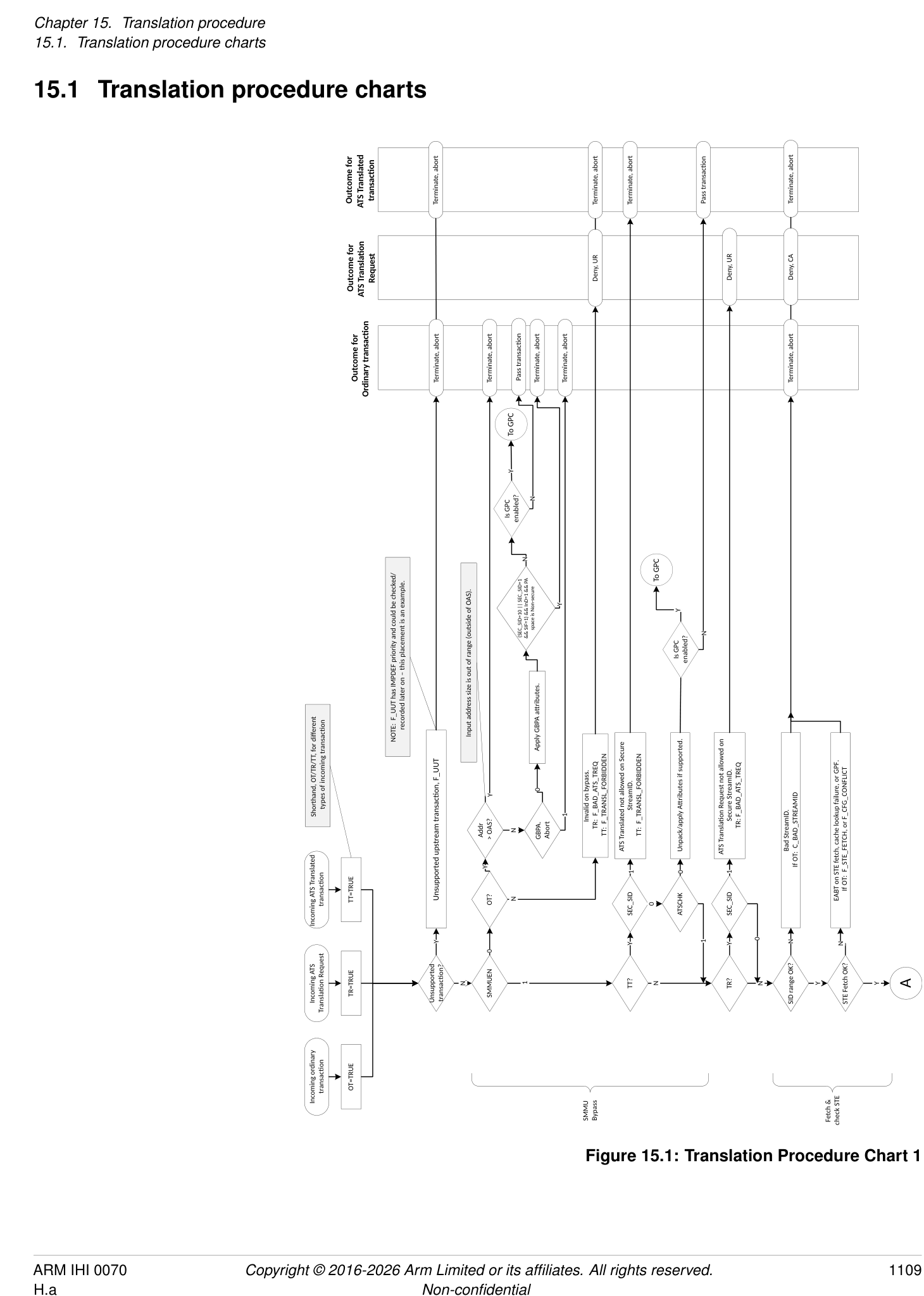
Outcome for ATS Translated transac�on Terminate, abort Terminate, abort Terminate, abort Terminate, abort Pass transac�on Terminate, abort
CA UR UR UR
Request Deny, Deny, Deny, Deny,
Outcome for ATS Transla�on
Outcome for Terminate, abort Terminate, abort Terminate, abort Pass transac�on Terminate, abort Terminate, abort N
Ordinary transac�on
Y
Is GPC enabled? To GPC
To GPC F_TRANSL_FORBIDDEN
F_PERMISSION Y 01
Y
N
N
Is GPC enabled? Y BAD_ATS_TREQF_ DPT check OK? 11 PRIVCFG, NSCFG}
Effec�ve STE.EATS=00 if STE.Config=100 Perform STE.{INSTCFG, overrides as applicable.
N This is the only error recorded for ATS TRs. F_TRANSL_FORBIDDEN
((SEC_SID=01 && SIF=1) || SEC_SID=10) && InD=1 && PA space is Non-secure 01 (Full ATS enabled)
00 (ATS disabled)
11 (Full ATS with DPT checks)
C_BAD_SUBSTREAMID
value used
STE.EATS
OT: Stage 1 F_ADDR_SIZE
or TR: Illegal on bypass, F_BAD_ATS_TREQ TT: Illegal on bypass, F_TRANSL_FORBIDDEN Effec�ve value of STE.EATS=00 if Reserved Check for EATS=10 behaving as 00 if ATSCHK=0. plit-stage ATS)10 (S
OT: No Stage 1 for substream,
OT: Apply STE override a�ributes checks against configura�on.
, no event recorded.
Here, ATSCHK=1 (as ATSCHK=0 TT exited the
If OT: C_BAD_STE Y Y N Y 00 (ATS disabled) flowchart early, above). Therefore in this branch it
STE.V=0 disables stream STE.V=1 but contents ILLEGAL. Silently terminated Y (effec�ve EATS=00) STE.Config[2:0] must be 111 (both S1 & S2 transla�on) for STE to be valid with EATS=10. For a�ributes, see chapter 13.6 PCIe and ATS a�ribute/ permissions handling.
TR or TT? N SSID present? N Addr > OAS? Effec�ve STE.EATS Other =10 && EATS ATSCHK=0
N 000 Y Y N Y Perform STE.{INSTCFG, as applicable.
PRIVCFG, NSCFG} overrides
A STE valid, not ILLEGAL? Y STE. Config 1xx S1+S2 Bypass? N TR? N TT? N a�ributes Check SSID
OT & TR: Apply STE override
2
To Stage
Fetch & check STE Stream Bypass ATS TR and TT
Figure 15.2: Translation Procedure Chart 2
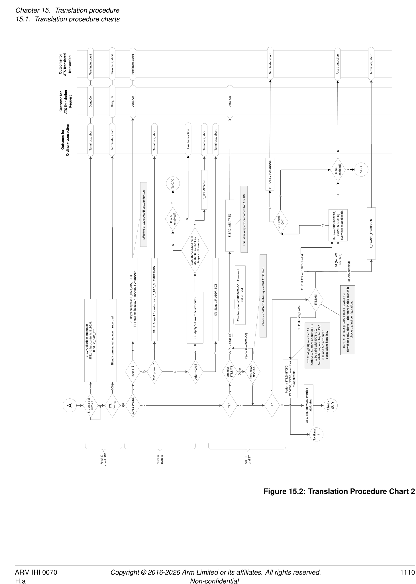
n/a
Outcome for ATS Translated transac�on
Request Deny, CA
Outcome for ATS Transla�on Complete, R=W=0
Outcome for Terminate, abort Terminate, abort
Ordinary transac�on
No Stage 1 for substream. OT: C_BAD_SUBSTREAMID S1 bypass address too large. OT: Stage 1 F_ADDR_SIZE Substreams disabled. OT: C_BAD_SUBSTREAMID Substream outside legal range. OT: C_BAD_SUBSTREAMID Substream 0 reserved. OT: F_STREAM_DISABLED Non-substream traffic disabled. OT: F_STREAM_DISABLED S1 bypass address too large. OT: F_ADDR_SIZE
Y 00 Y
Y Y N Y SSID=0 N STE.S1DSS Other STE.S1DSS 01 Addr > IAS?
10 10 N
CD table entry 0 used
SSID present? N Addr > IAS? STE.CDMax > 0? Y SSID > STE.CDMax N STE.S1DSS Other
N
S2 translates.
Stage 1 + Stage 2 bypass dealt with above, so no-S1 implies
N Y Y
Check SSID Y Got VA N 0? N B
S1 translates? SSID present? STE.CDMax >
To Stage 2 Skip Stage 1
Check Sub stream ID
Figure 15.3: Translation Procedure Chart 3
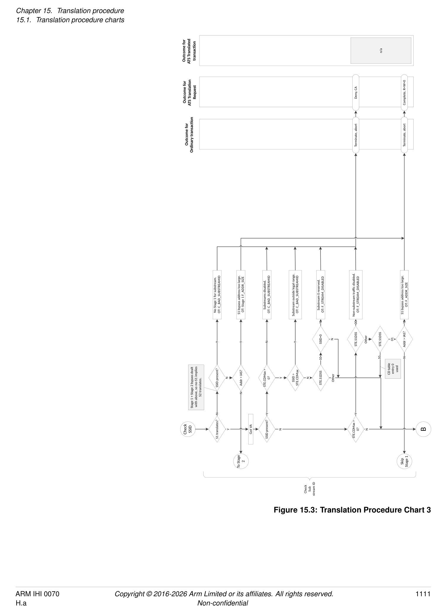
n/a
Outcome for ATS Translated transac�on
n/a
Request Deny, CA Deny, CA
Outcome for ATS Transla�on Complete, R=W=0
Stall
Outcome for Terminate, abort Terminate, abort Terminate, abort
Ordinary transac�on
detect a different error.
1
0
STE.S2S
For Stage 1 + Stage 2 ATS (including Split-stage ATS, and with PRI at both levels), this case returns ‘R=W=0’ to elicit a PPR from the endpoint. The Hypervisor (HV) traps the PPR for VA and translates it to determine that the CD fetch faulted. The HV might make the page available and con�nue. However, if the guest used a genuinely bad CD IPA the nearest equivalent is an abort on CD read (from IPA). The guest can detect that ATS to a stream with a bad CD address seemed to succeed (R=W=0) instead of Deny, CA. In either case, device access is safely denied but the guest OS could
IPA.
STE.S2HA=0) failure, or GPF.
(CLASS=CD, Stage=2)
might be transient OT: F_TRANSLATION/F_ADDR_SIZE/ F_PERMISSION (/F_ACCESS, if Stage 2 TTD fetch EABT, TLB lookup F_TLB_CONFLICT (Stage=2)
due to S2 paging. Transla�on-related fault at Stage 2 for CD- OT: F_WALK_EABT (CLASS=CD, Stage=2),
S2 fault
N
might respond by injecting F_CD_FETCH to guest Non- Y
transla�on read error?
Or, if it’s a genuinely bad address, HV
N
OK? Y
S2 translate
, or GPF.
-IPA. Invalid CD.
set OT: C_BAD_CD
OT: F_CD_FETCH, or F_CFG_CONFLICT
S2 translate for CD HTTU: If STE.S2HA=1, set S2-TTD.AF=1 if not already EABT on fetch, cache lookup failure
Y N N
B N Y CD valid? Y Walk Stage 1
S2 translates? CD fetch OK?
Fetch CD
Figure 15.4: Translation Procedure Chart 4
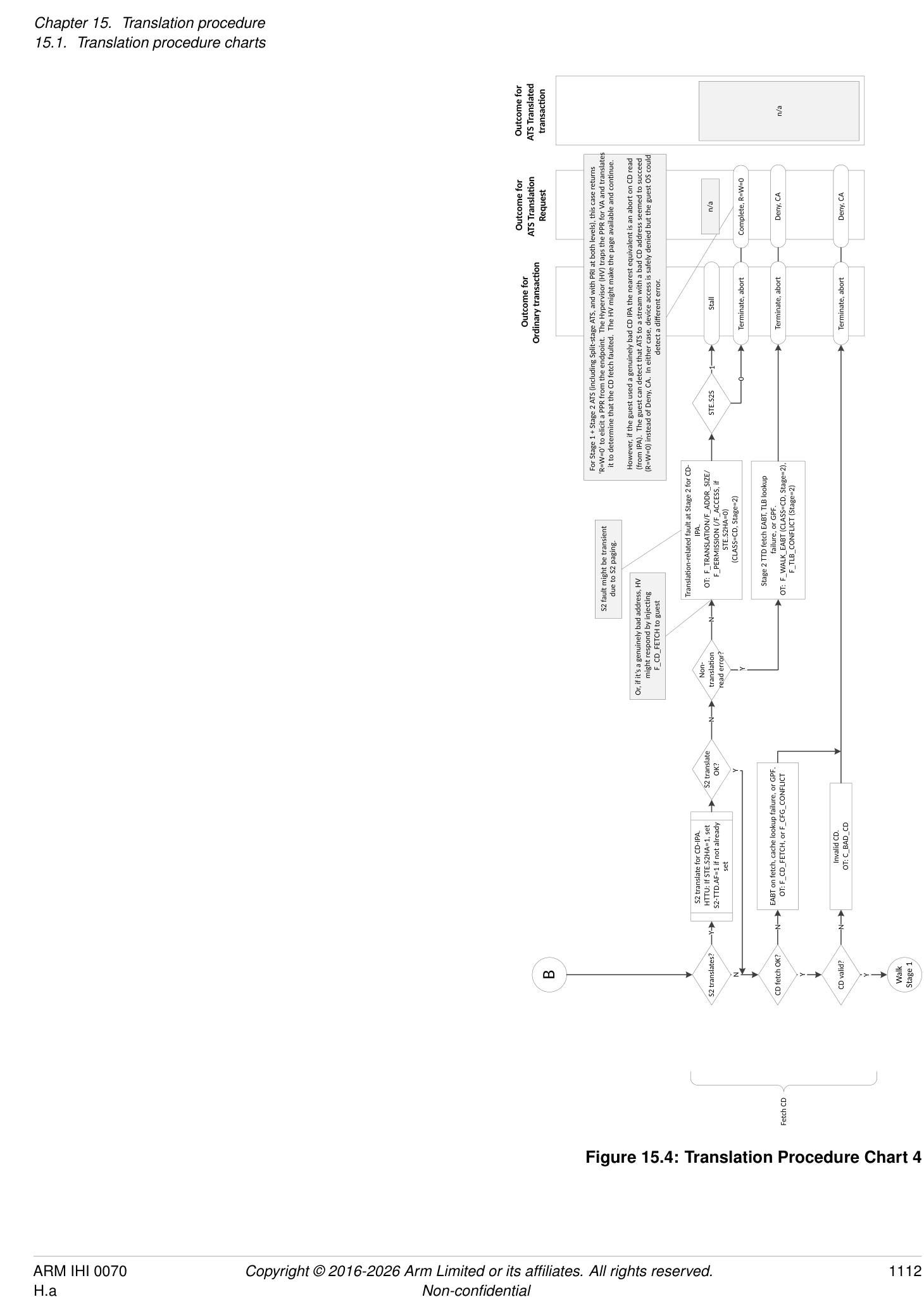
n/a
Outcome for ATS Translated transac�on
n/a n/a
Request Deny, CA Deny, CA Deny, CA Deny, CA
Outcome for ATS Transla�on Complete, R=W=0 Complete, R=W=0 Complete, R=W=0
CD.A=0 and CD.S=1 have no effect on a TR. ATS does not support RAZ/WI aborts.
RAZ/WI
Stall Stall Stall
Outcome for Terminate, abort Terminate, abort Terminate, abort Terminate, abort Terminate, Terminate, abort Terminate, abort Terminate, abort
Ordinary transac�on
1 0 1 0
1
0
STE.S2S CD.A STE.S2S
0 a�empted.
, or GPF.
1 CD.S This flow depicts S2-TTD being updated
NOTE: with AF=1, then later Dirty=1 (e.g. fetch S1-TTD then later decide to update it – atomically). If S2 maps S1 read-only, could result in S2 having AF=1 yet later an S2 fault when Dirty update is
update IPA. F_WALK_EABT
tage 2 is R/O for S1-TTD.S OT: F_PERMISSION from S2-TTD backing S1-TTD’s (CLASS=TT, Stage=2) OT: (CLASS=TT, Stage=2)
might be transient due to S2 paging. Stage 2 fault: OT: F_TRANSLATION, backing S1-TTD IPA. (CLASS=TT, Stage=2) F_TLB_CONFLICT (Stage=2) , or GPF. N
S2 fault F_ADDR_SIZE, F_PERMISSION, OT: F_WALK_EABT (CLASS=TT, Stage=2),
(F_ACCESS if STE.S2HA=0) from S2-TTD Stage 2 TTD fetch EABT, TLB lookup failure Y
Race condi�on, no abort when it was read but now could EABT when write a�empted read?
N EABT on TTD
Stage 1 fault: TTD of VA.
F_TLB_CONFLICT (Stage=1) (CLASS=IN, Stage=1) && SIF=1 && NS=1. for write N
Non- transla�on read error? Y Stage 1 TTD fetch EABT, TLB lookup failure OT: F_WALK_EABT (CLASS=TT, Stage=1), OT: F_TRANSLATION, F_ADDR_SIZE, (F_ACCESS if last-level TTD && CD.HA=0), F_PERMISSION (affected by CD.HD=0) from S1- Or, F_PERMISSION due to SEC_SID=1 && InD=1 e-access Stage 2 TTD, but R S1-TTD write IPA. set S2 translate OK? F_WALK_EABT
N OT: (CLASS=TT, Stage=1)
S2 walk for HTTU: If STE.S2HD=1 update S2-TTD.Dirty=1 if not already
Y
OK? Y
S2 translate Y
TTD
N
Y write?
S2 translates? Update S1-TTD EABT on
translated to PA
Input address out of range (considering S1-TTD read IPA. already set IPA Non- transla�on read error? N
StreamWorld, CD.TxSZ, CD.TBI), or effec�ve EPD S2 walk for HTTU: If STE.S2HA=1, update S2-TTD.AF=1 if not Atomic Y N
N
Fault Y
TTD
Walk Stage 1 Transla�on Fault? N Construct S1-TTD address (IPA/PA) S2 translates? N Read S1-TTD from PA Stage 1 OK and not GPC fault? Y -level Last TTD? Y S1 HTTU required? N Got IPA C
N
Walk Stage 1 TT
Figure 15.5: Translation Procedure Chart 5
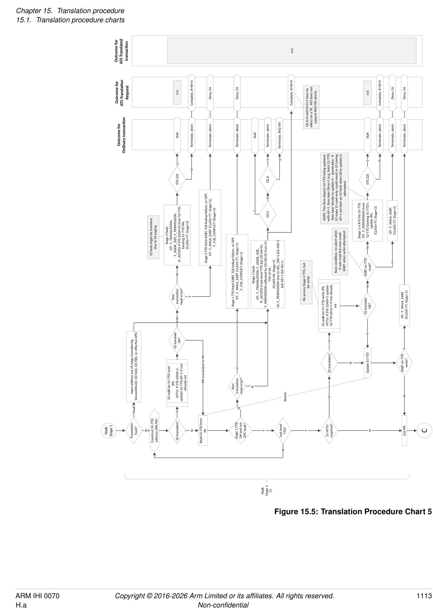
n/a
Outcome for ATS Translated transac�on Terminate, abort Terminate, abort Terminate, abort Pass transc�on (apply a�rs as appropriate) Terminate, abort Pass transac�on (Combine in S2 a�rs)
n/a
PA=VA, U=0, from
Outcome for ATS Transla�on Request R=W=1 from S1 table walk Deny, CA Complete, R=W=0 Deny, CA S1+S2; return IPA appropriate) Deny, CA
Complete, Complete, perms & PA Complete, perms Complete (apply a�rs as Complete, perms & PA from (S1+)S2 table walk
(apply (apply
Stall
S1 a�rs)
Outcome for Ordinary transac�on Terminate, abort Pass transac�on Terminate, abort Terminate, abort Terminate, abort Pass transc�on (apply a�rs as appropriate) Terminate, abort Pass transac�on (S1+)S2 a�rs)
1 0
STE.S2S
15.
might be transient
due to S2 paging.
To GPC
N S2 fault
Is GPC enabled? Y same as input (since EATS=10 means only Stage 1 is translated using ATS). , or N
If S1DSS=01 causes Stage 1 to be skipped when EATS=10, the output address is the However, this carries on to Stage 2 to check permissions/a�ributes. See Chapter Y
GPC fault?
GPF. F_WALK_EABT
Stage 2 fault:
F_PERMISSION TR with EATS=10: F_TLB_CONFLICT (Stage=2) OT/TT: F_TRANSLATION, F_ADDR_SIZE, F_PERMISSION, (affected by STE.S2HD=0) from S2-TTD of IPA (Stage=2, CLASS=IN) OT/TT: (WALK=TTD, Stage=2)
Stage 2 for permissions.
Store Input address as IPA to return in result, con�nue to Stage 2 TTD fetch EABT, TLB lookup failure OT/TT: F_WALK_EABT (CLASS=IN, Stage=2), (F_ACCESS if STE.S2HA=0), F_PERMISSION
To GPC
Y Y
TTD (i.e. GOTO Read S2-TTD)
N Atomic: May “load-exclusive, test/
For regular EATS=01 ATS, Stage 1 has been skipped due to S1DSS=01 and Stage 2 does not translate. EATS=01 && STE.Config[1]=0 N EATS=10? N To GPC TR with EATS=10: manipulate, store-exclusive” in some systems or “read, test/manipulate, far CAS” or similar; if the TTD has changed in between, re-read N N
Y
N are combined S1+S2 permissions)
Y Is GPC enabled? Y Store IPA to return in final result, con�nue to Stage 2 for permissions (result’s permissions Input address out of range (considering STE.S2T0SZ) Y Non- transla�on read error? Update S2-TTD EABT on S2- TTD Is GPC enabled? Y Y Is GPC enabled?
Skip Stage 1 TR?
N Y N Y Fault N Atomic N Y
C N S2 trans? Y TR && EATS=10? N Transla�on Fault? N Construct S2-TTD address (PA) Read S2-TTD from PA TTD OK and not GPC fault? Y Last TTD? Y S2 HTTU required? N TR && EATS=10? N Got PA
space is Non-secure
(SEC_SID=10 || SEC_SID=1 && SIF=1) && InD=1 && PA
N
2
To Stage
Walk Stage 2 TT
Figure 15.6: Translation Procedure Chart 6
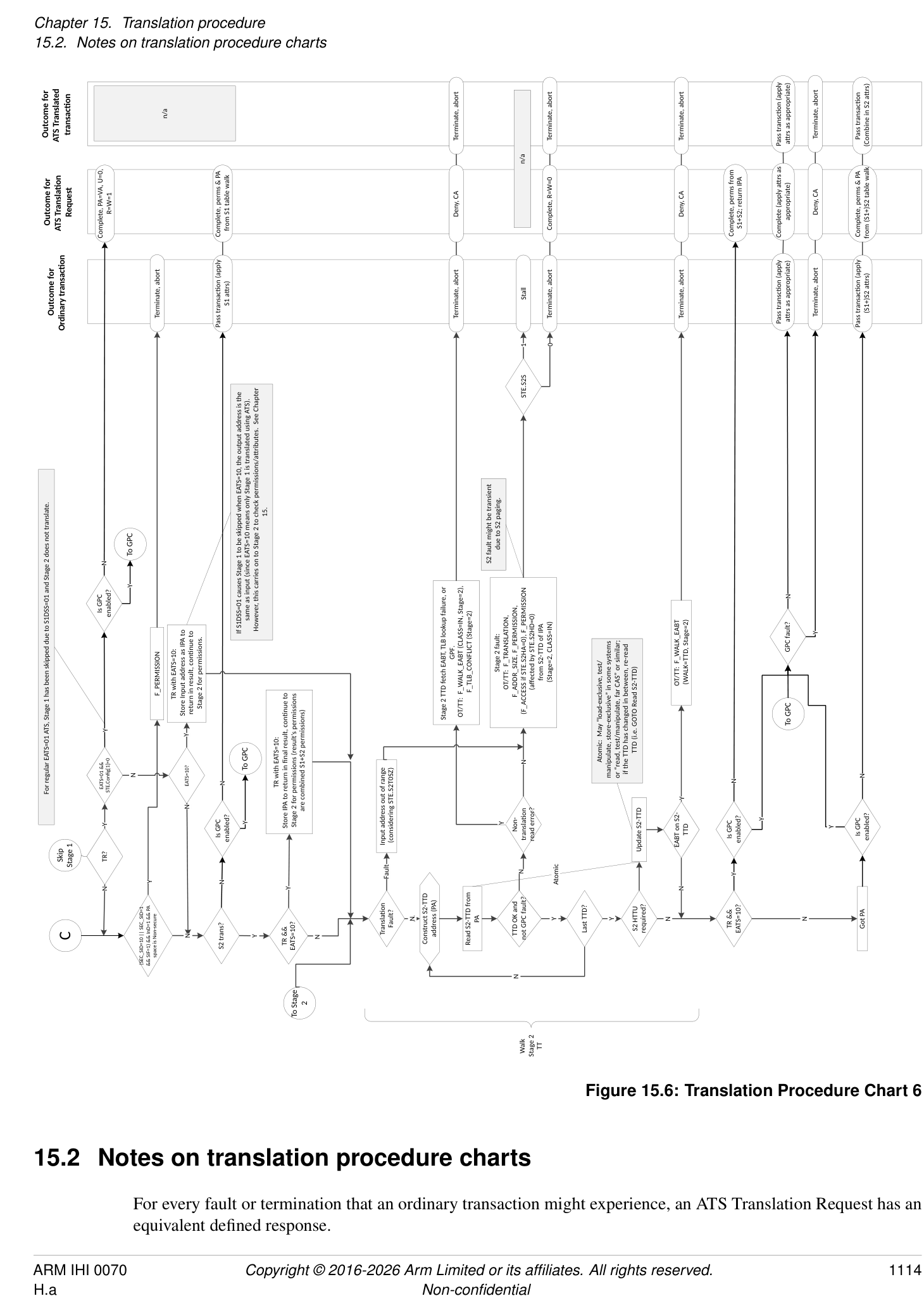
15.2 Notes on translation procedure charts
For every fault or termination that an ordinary transaction might experience, an ATS Translation Request has an equivalent defined response.
Similarly, an ATS Translated transaction might experience a subset of the fault or termination reasons.
Generally, situations that represent a configuration error result in a Completer Abort (CA) response to the endpoint, situations that represent an explicit prevention or disable of ATS service result in an Unsupported Request (UR) response, and Translation-related failures result in a successful Translation Completion having R == W == 0 (that is, no access for this address).
See section 3.9.1.2 Responses to ATS Translation Requests .
System and Implementation Considerations
Chapter 16 System and Implementation Considerations
16.1 Stages
Arm strongly recommends that stage 2 is only used to provide device assignment to a guest OS. To support other usage scenarios, Arm recommends implementations also implement stage 1 if stage 2 is implemented.
16.2 Caching
An SMMU implementation is not required to implement caching of any kind, but Arm expects that performance requirements will require caching of at least some configuration or translation information.
Caching of configuration or translations might manifest as separate caches for each type of structure, or some combination of structures into a smaller number of caches. When architected structure types are cached together as one combined entry, the invalidation and lookup semantics remain identical to many specialized per-structure caches.
For example, an implementation with caches of each structure and translation stage implemented separately would contain:
-
An STE cache
-
Indexed by StreamID.
-
Invalidated by StreamID, StreamID-span, or all.
-
Might contain a Level 1 Stream table cache of pointers to 2nd-level Stream table.
- [Identical index/invalidation requirements.]
-
-
A CD cache
-
Indexed by StreamID and SubstreamID, or address.
- [Note:][Address index could be used, calculated from the][ STE.S1ContextPtr][ of a prior STE lookup] plus the incoming SubstreamID. This arrangement might be useful where many STEs share a common table of CDs.
-
Invalidated by StreamID and SubstreamID, StreamID, or all.
-
Might contain a Level 1 CD table cache of pointers to 2nd-level CD table.
- [Identical index and invalidation requirements.]
-
-
A VMS PARTID_MAP cache
-
Indexed by VMID, or StreamID.
- [Note:][A VMS cache might be indexed by StreamID, but this would be no different from storing] VMS data as part of an STE cache.
-
Invalidated by VMID, or StreamID.
-
-
A stage 1 TLB (VA to IPA).
-
Indexed by VA, ASID, VMID and EL.
- [EL is the Exception level or StreamWorld on whose behalf the TLB entry was inserted.]
-
Invalidated by VA, ASID, VMID and EL, or ASID, VMID and EL, or VMID and EL, or EL.
-
Might contain or be paired with a walk cache (invalidated under the same conditions as PE translation walk caches).
-
-
A stage 2 TLB (IPA to PA)
-
Indexed by IPA , VMID and EL.
-
Invalidated by IPA and VMID, or VMID, or all.
-
Might contain or be paired with a walk cache.
-
In this example, consistency is maintained by looking up cache entries in order from STE through CD, then using the parameters determined from that stream configuration to lookup in the TLBs. That is, given a StreamID, SubstreamID and VA input, convert StreamID and SubstreamID into ASID, VMID and Exception level, then use VA, ASID, VMID and EL to lookup in the TLBs.
16.2.1 Caching combined structures
Note: In the example given in 16.2 Caching , a stage 1 TLB is implemented separately to the stage 2 TLB. While this layout mimics the two stages of translation table, it might not provide optimal performance. A designer might determine that a combined stage 1 and stage 2 TLB is better, where each entry would translate VA to PA directly but would inherit invalidation requirements from both original structures.
For translations and TLBs, the SMMU invalidation rules for combined TLBs directly match those of Armv8-A.
Note: For example, an invalidation by IPA is not required to invalidate entries in a combined S1 and S2 TLB but is required to be paired with a second invalidation by VA or stage 1-all that would affect S1 and S2 TLB entries.
Combined structure caches maintain the same invalidation semantics as discrete structures. An entry of a combined cache is invalidated if any part of the entry would have been invalidated in an equivalent operation, with the same parameters, on a discrete cache.
Note: For example, a particular SMMU implementation maintains only two hardware caches, a combined cache of STE and CD, and a TLB. In this layout, a StreamID and SubstreamID and VA input looks up StreamID and SubstreamID in the combined cache and determines the ASID, VMID, and StreamWorld at the same time. The translation is then looked up using VA, ASID, VMID and StreamWorld to determine the PA. The invalidation requirements of the combined STE and CD cache are the union of the requirements of the separate structures. STE invalidation operations invalidate every combined cache entry that contains data loaded using a given StreamID. This covers all CDs fetched from a given STE, which is implied anyway by the CMD_CFGI_STE to invalidate CDs subordinate to the STE. Conversely, every entry that contains data from a CD to be invalidated must be invalidated even if the STE portion is still valid.
An implementation might combine a TLB with configuration caching so that a single cache is looked up by StreamID and SubstreamID and VA and results in a PA output. Entries in this cache are invalidated when any part of an entry would match (or cannot be proven to not match) a required invalidation for STE, CD or translation.
Note: Implementations must balance a trade-off between over-invalidation that might be necessary to cover all required entries, and the cost of adding extra tagging. For example, a single cache might tag entries by VA, ASID, VMID, and StreamID so that broadcast TLB invalidations can remove only relevant entries, or so that an STE invalidation removes only entries that could have been constructed from the given StreamID.
16.2.2 Data dependencies between structures
The configuration structures logically make a tree or graph by indicating subsequent structures (and onwards, indicating translation tables). The structures contain fields to locate the next structure in the chain but might also modify interpretation of subsequent structures.
The dependencies between structures are:
-
STE to CD to TT (stage 1)
-
STE to TT (stage 2)
(Here, ‘STE’ might be composed of multi-level L1STD to STE lookups and CD might be composed of multi-level L1CD to CD lookups.)
The STE contains fields that determine how to locate a CD and stage 2 translations (whichever are relevant to STE.Config) but also contains fields that modify the behavior of a CD and translation table walks performed through it. For example:
-
The STE StreamWorld (STRW plus STE Security state) determines the translation regime, which:
-
Tags caches of translations subsequently inserted, to separate lookup and match on invalidation
-
– Determines which translation table formats are valid for use by the CD.
-
-
STE.S1STALLD modifies CD.S behavior upon stage 1 fault.
-
VMSAv8-32 LPAE stage 2 translation (STE.Config[1] == 1 and STE.S2AA64 selects VMSAv8-32 LPAE) causes a 64-bit stage 1 CD (CD.AA64 == 1) to be ILLEGAL.
Note: A change to an STE field requires an STE invalidation. An STE invalidation also invalidates all CDs that were cached through the STE.
The CD contains fields that determine how to locate translation tables but also contains fields that modify the behavior of a translation table walk through it:
-
CD.{AA64, EPDx, SHx, ORx, IRx, TGx, TxSZ, ENDI, NSCFGx} govern walks of the translation table itself. In addition, NSCFGx can influence the NS attribute output from stage 1, because a translation table walk made to memory that is marked as Non-secure at stage 1 can never provide an output address that is Secure at the output of stage 1.
-
CD.{UWXN, WXN, PAN, AFFD, HADx} govern permission checking with the translation table descriptors.
-
CD.{ASID, ASET} govern ASID-tagged TLB entries.
-
CD.{MAIR, AMAIR} modify the attribute determined from translation.
-
CD.{HA,HD} determines HTTU configuration for walks performed through TTB{0,1}.
Some STE and CD fields are permitted to be cached as part of a translation or TLB entry (therefore requiring invalidation of TLB entries that might contain the old value when the fields are changed). These fields are noted in sections 5.2 Stream Table Entry and 5.4.1 CD notes . With the exception of these fields, no other information is expected to be ‘carried forward’ between structures.
Some configuration register fields are, where indicated, permitted to be cached in a TLB. Changes to these fields require invalidation of any TLB entries that might cache a previous value of the field.
16.3 Programming implications of bus address sizing
If pointers are programmed into a device from the PE that would, on the PE, cause translation faults due to failing sign-extension checks, the SMMU will also raise a translation fault because of the sign-extension checks on input. However, if a system cannot convey all 64 address bits from a device, or a device lacks the ability to register upper address bits, the SMMU does not have enough information to perform these checks. In this case, Arm recommends that if detection of such errors is required, software (or the device, if it has the facility to hold the full address) checks the validity of upper bits.
On Armv8-A PEs, the TBI facility allows the top byte of addresses to contain tags that are ignored when checking address sign-extension validity. If an address is truncated to <= 56 bits on the flow through device DMA registers to device DMA accesses to I/O interconnect to the SMMU, the SMMU cannot check the validity of the top byte so effectively TBI is always used. In such a system, another entity (device, software) must check addresses if required.
16.4 System integration
-
The SMMU must be in the same Shareability domain as any other agents that might use DVM with the SMMU.
-
In systems implementing architectures prior to Armv8.4, DVM messages are only broadcast over the Inner Shareable domain.
-
Some systems implementing Armv8.4 may broadcast DVM messages over the Outer Shareable domain.
-
In general, Arm does not expect SMMUs to be connected in series.
-
Note: This topology needs special software support, particularly when different software modules manage different SMMUs. This must not be used to construct two stages of translation using two SMMU implementations that support only one stage, as it is programmed differently to an SMMU that supports both stages.
-
When used with a PCIe subsystem, an SMMU implementation must support at least the full (16-bit) range of PCI RequesterIDs and the system must ensure that a Root Complex generates StreamIDs from PCI RequesterIDs (BDF) in a one to one or linear fashion so that StreamID[15:0] == RequesterID[15:0]. A larger StreamID might be constructed by concatenating the RequesterIDs from multiple PCI domains (or “segments” in ACPI terminology), for example:
-
StreamID[17:0] == { pci_rc_id[1:0], pci_bus[7:0], pci_dev[4:0], pci_fn[2:0] };
that is, StreamID[17:0] == { pci_domain[1:0], RequesterID[15:0] };
When used with a PCIe system supporting PASIDs, Arm recommends that the SMMU supports the same number of (or fewer) PASID bits supported by client Root Complexes so that software is able to detect end-to-end SubstreamID capabilities through the SMMU.
-
If accesses from a device are expected to experience page faults and the Stall model is used, Arm recommends that a system does not depend on other devices on the same SMMU path as the device in order to resolve the faults. Because a stalled transaction occupies an input buffer resource, the SMMU might not guarantee to pass traffic whether faulting or not, and any new request for device DMA might deadlock.
-
Streams belonging to PCIe endpoints must not be stalled. The Terminate model is the only useful option. Stalling PCIe transactions risks either timeouts from the PCIe endpoint (which might be difficult to recover from), or deadlock in certain scenarios. A system is permitted to enforce this, for safety reasons. See section 3.12 Fault models, recording and reporting .
-
Specifically, PCIe traffic (especially if configured to Terminate, architecturally not stalling) must not be held up waiting for any PE action, including draining the Event queue or restarting stalled transactions. PCIe traffic must always make forward progress without unbounded delays dependent on software. An implementation must ensure that transactions to be terminated are not blocked by any other users of the SMMU which might consume resources or stall transactions for an indefinite time.
16.4.1 System integration for an SMMU with RME DA
16.4.1.1 StreamID
For a device interface that might operate in a trusted or untrusted mode (that is, such that SEC_SID = Non-secure or Realm), the StreamID presented to the SMMU is the same across the two modes.
16.4.1.2 DeviceID
According to the PCIe specification regarding the TDISP feature [1], a TDISP-compliant device might issue MSIs in two manners:
-
If the MSI is configured via the MSI capability in configuration space, it is sent to the host SoC with T = 0 and therefore presented to the SMMU with SEC_SID = Non-secure.
-
If the MSI is configured via the MSI-X capability in the protected MMIO region of the device interface, it is sent to the host SoC with T = 1 and therefore presented to the SMMU with SEC_SID = Realm.
MSIs from a single device interface are presented to the GIC ITS interface with the same DeviceID regardless of which MSI mechanism is used.
Note: The target PA space of an MSI is determined from configuration in translation tables, the DPT and the configuration structures for the programming interface, StreamID and address for the target of the MSI, consistent with the behavior for any client-originated access. See 3.18 Interrupts and notifications , 3.10.1 StreamID Security state (SEC_SID) , and 3.10.2 Support for Secure state .
16.5 System software
Note: Software must:
-
Not assume that both stage 1 and stage 2 are implemented.
-
Support systems in which broadcast TLB invalidation messages are not supported so do not invalidate SMMU TLB entries, that is fall back to software TLB invalidation messages.
-
Discover StreamID and SubstreamID sizes and capabilities.
-
Probe SMMU_IDR1 for PRESET configuration table and queue base pointers, only allocating memory for pointers that require initialization.
-
Discover the maximum table sizes of the SMMU rather than using fixed-size tables.
-
Not make assumptions about which SMMU Security state or states it is interacting with, and not make assumptions about which Security states are supported in the SMMU.
-
Present system-specific StreamIDs as part of firmware descriptions for each device, as the StreamIDs associated with a physical device are system-specific.
-
Ensure that when HTTU is not used, descriptors mapping DMA memory are marked Accessed (and not Read-Only, if DMA writes are expected) in order to avoid faults.
16.6 IMPLEMENTATION DEFINED features
16.6.1 Configuration cache locking and TLB locking
Note: The lockdown of configuration cache entries and TLB entries is not a feature directly described by the SMMU architecture because cache structures might vary between implementation and entry lockdown might expose this layout to software.
An implementation might support cache locking in an IMPLEMENTATION DEFINED manner using registers in the IMPLEMENTATION DEFINED memory map.
Note: These registers might expose cache contents and provide insertion, probe and invalidation operations.
If an implementation supports TLB locking, TLB invalidation must be consistent with the Armv8-A rules on locked entries:
-
A TLB invalidate-all operation does not invalidate locked entries.
-
An implementation might choose to implement TLB invalidate-by-VA or invalidate-by-ASID operations so that they do one of the following:
-
Invalidate locked entries that are explicitly matched by the operation.
-
Do not invalidate locked entries.
-
A locked TLB entry is not affected by over-invalidation side effects of invalidation operations that do not directly match the entry.
The behavior of CMD_CFGI_* commands with respect to locked configuration cache entries is IMPLEMENTATION DEFINED.
See SMMU_S_INIT.INV_ALL, this initialization invalidate-all operation invalidates locked entries.
16.7 Interconnect-specific features
16.7.1 Reporting of Unsupported Client Transactions
The SMMU behaves as though a single transaction is associated with one translation.
SMMU implementations might define their own input alignment restrictions leading to an unsupported client transaction error. For example, an implementation with an AMBA downstream interconnect is likely to treat an incoming transaction that crosses a 4KB boundary as unsupported, because these would violate the alignment rules of the downstream interconnect.
For AMBA 4 systems the following upstream client transactions are unsupported:
- Far Atomic operations (see section 16.7.6 Far Atomic operations ) where not supported by the downstream interconnect or SMMU implementation.
Such transactions will be aborted and an F_UUT event will be recorded if possible.
16.7.2 Non-data transfer transactions
Some interconnect architectures support transactions that do not perform a data transfer, prefetch or translation request action.
If the input interconnect can express the following transactions from client devices, the transactions will be terminated silently by the SMMU as SLVERR (or equivalent on non-AMBA interconnect):
-
DVM operations (of all sub-types).
-
Barriers.
The interconnect architecture of an implementation might support the following non-data operations, also known as Cache Maintenance Operations (CMOs), that perform address-based cache maintenance:
-
Clean.
-
Invalidate.
-
CleanInvalidate.
-
CleanToPersistence.
-
Destructive hint (DH): Operation that has a hint side effect of invalidate.
Note: In AMBA AXI [8], the equivalent of the above operations are the CleanShared, MakeInvalid, CleanInvalid, CleanSharedPersist and InvalidateHint transactions, respectively.
SMMUv3.0:
- The SMMU does not support CMOs. If an SMMUv3.0 implementation can receive these operations from client devices, they are handled in an IMPLEMENTATION DEFINED way. A system that requires SMMU support for CMOs is required to implement SMMUv3.1 or later.
SMMUv3.1 and later:
-
CMOs that are not address-based are not supported and are silently terminated by the SMMU.
-
CMOs are permitted to pass into the system, without the transformation described in section 16.7.2.1 Control of Cache Maintenance Operations , when the transaction bypasses all implemented stages of translation. See section 16.7.2.3 Memory types and Shareability for Cache Maintenance Operations on memory types.
- Note: For a Secure stream, SMMU_S_CR0.SIF still applies. See section 16.7.2.2 Permissions model for Cache Maintenance Operations .
-
When one or more stages of translation is applied, the SMMU allows these operations to progress into the system subject to the configuration controls and permission model described in sections 16.7.2.1 Control of Cache Maintenance Operations and 16.7.2.2 Permissions model for Cache Maintenance Operations . Additionally, Invalidate operations might be transformed into Clean and Invalidate operations as part of these checks.
-
When the input interconnect can deliver these operations, but the output interconnect does not support them, the transactions are silently terminated.
SMMU implementations supporting AMBA might define an IMPLEMENTATION DEFINED set of unsupported incoming transactions.
SMMU implementations supporting other interconnects might define their own set of unsupported incoming transactions.
Note: See section 3.22 Destructive reads and directed cache prefetch transactions . A destructive read (read with invalidate), write with directed prefetch, or standalone directed prefetch transaction is not considered to be a discrete Cache Maintenance Operation and is handled differently.
16.7.2.1 Control of Cache Maintenance Operations
In SMMUv3.1 and later, STE.DRE controls whether an Invalidate operation is transformed as follows:
| Input transaction | |||
|---|---|---|---|
| class | DRE == 0 | DRE == 1 | Notes |
| Invalidate | Transformed into | Eligible for output as Invalidate | IfSMMU_IDR3.MTCOMB is |
| CleanInvalidate. The | (if permissions checks allow) | 1, then for a Forced-WB | |
| operation is treated identically | transaction, the value of | ||
| to a CleanInvalidate for | STE.DREis treated as 0. | ||
| permission evaluation. | |||
| Destructive hint (DH) | Transformed into No-op. | Eligible for output as | IfSMMU_IDR3.MTCOMB is |
| destructive hint (if permissions | 1, then for a Forced-WB | ||
| checks allow) | transaction, the value of | ||
| STE.DREis treated as 0. |
The STE.DRE field applies in this manner when one or more stages of translation are applied. This does not include the case where the only stage of translation is skipped due to STE.S1DSS.
16.7.2.2 Permissions model for Cache Maintenance Operations
In SMMUv3.1 and later, the SMMU_S_CR0.SIF permission check applies to Cache Maintenance Operations (CMOs). This applies when either translation or bypass occurs.
In SMMUv3.1 and later, when one or more stages of translation are applied, the following permissions are required for CMOs:
| Maintenance operation type | Required permissions | Behavior if permissions not met |
|---|---|---|
| Clean, | Identical to ordinary read: | Identical to ordinary read. |
| CleanInvalidate, | Requires Read or Execute permission, | |
| CleanToPersistence | (depending on input InD and INSTCFG) at | |
| privilege appropriate to PnU input and | ||
| STE.PRIVCFG. | ||
| Invalidate | To progress as Invalidate, requires both | If no Read/Exec permission is available |
| Read-or-Execute permission (depending on | behavior is identical to an ordinary read. | |
| input InD and INSTCFG) and Write | If Read/Exec permission is available but | |
| permission at a privilege appropriate to the | Write permission is not, an Invalidate is | |
| PnU input andSTE.PRIVCFG. | transformed into a CleanInvalidate | |
| operation.(1) |
| Maintenance operation type | Required permissions | Behavior if permissions not met |
|---|---|---|
| Destructive hint (DH) | To progress as destructive hint, requires both | Invalidate does not occur.(1)(2) |
| Read-or-Execute permission (depending on | ||
| input InD andSTE.INSTCFG), and Write | ||
| permission that does not result in HTTU | ||
| update of Dirty state, at a privilege appropriate | ||
| to the PnU input andSTE.PRIVCFG. |
(1) This includes the case where a GPC does not grant write permission when SMMU_ROOT_IDR0.GDI == 1. See 3.25.10 Granular Data Isolation .
(2) A DH operation is a hint. If the required permissions are not met for a DH at a given stage of translation, the DH operation is treated as a No-op and does not progress into the system. If HTTU of dirty state is enabled, a DH operation does not mark a page Dirty. If the translation for a DH operation is writable-clean, the SMMU does not perform the hardware update of dirty state and instead the DH operation is treated as a No-op and does not progress into the system. If a DH operation is permitted to progress through a stage of translation and HTTU of Access flag is enabled for that stage, AF is updated. If the translation conditions permit an AF update, but the DH is not permitted to progress into the system, a coincidental speculative update of AF might occur.
If a Clean, CleanInvalidate, Invalidate or CleanToPersistence operation leads to a fault, it is recorded as a read, that is RnW == 1. The read can be treated as either data or instruction, depending on the input InD/INSTCFG. On fault, these operations stall in the same way as an ordinary read transaction if the SMMU is configured for stalling fault behavior. Retry and termination behave the same as for an ordinary read or write transaction. If these transactions are stalled and retried, they are retried as the same transaction type. A DH transaction does not cause faults in the SMMU nor does it cause an abort response to be returned where the interconnect architecture requires a response.
An implementation is permitted to downgrade a DH operation as described in this section, for any reason.
Note: The input interconnect might supply all CMOs as Data.
See section 3.13.8 Hardware flag update for Cache Maintenance Operations and Destructive Reads for information on the behavior of HTTU for Invalidate operations.
When HTTU is enabled for Access flag updates and the translation descriptor and AFFD configuration require it, a Clean, CleanInvalidate, CleanToPersistence, Invalidate, or DH operation updates the Access flag. See section 3.13.2 Access flag hardware update .
16.7.2.3 Memory types and Shareability for Cache Maintenance Operations
Cache Maintenance Operations (CMOs) do not have a memory type. If an input shareability is provided, it does not undergo any normalization before entering the attribute determination process described in Chapter 13 Attribute Transformation . If an input shareability is not provided, the default shareability is taken as described in section 13.1.3 Default input attributes . After input, the output Shareability of a CMO is determined in the same way to that of an ordinary transaction.
Note: This means that the input shareability of a CMO is not dependent on the input memory type even if the input bus encodes a memory type, because the SMMU does not consider a memory type to be provided on input for a CMO.
In SMMUv3.1 and later, this rule applies to all such operations in all translation and bypass configurations, including:
-
Global bypass (attribute set from GBPA).
-
STE bypass (whether STE.Config == 0b100 or STE.S1DSS and STE.Config == 0b101 causes skip of the only stage of translation).
-
Translation.
Note: On AMBA AXI5 interfaces [8], it is not permitted to issue CMOs, including the DH operations, with Sys shareability.
16.7.3 Treatment of AMBA Exclusives from client devices
The AXI specification does not permit Exclusive accesses to the Shareable domain. Therefore, if the SMMU interface to the system interconnect is AXI, an Exclusive access transaction that is translated into an Inner-shareable or Outer-shareable transaction cannot be marked as Exclusive.
Arm recommends that such transactions are transformed into non-Exclusives.
For more information about the relationship between AMBA and Armv8 output attributes, see section 16.7.5.2 Conversion of Armv8 attributes to AMBA on output and representation of Shareability .
The outcome of such a transformed Exclusive transaction is equivalent to that of an ordinary transaction and depends on whether the transaction experiences a fault and, if it faults, fault configuration. The transaction will experience one of the following:
-
Translates without fault, returning the non-exclusive transaction’s response to the upstream client device. A response of EXOK is not possible (as the transaction is now non-exclusive). A response of OK will be treated as an exclusive fail by the upstream client device.
-
Faults on translation and is terminated with abort. These aborts are reported to the upstream client device in the same way for transformed Exclusive transactions as for regular transactions (for example as SLVERR).
-
Fault on stage 1 translation and be terminated with RAZ/WI semantics because CD.A == 0. This returns a response of OK.
16.7.4 Treatment of downstream aborts
Some systems might allow a Completer device to abort transactions, returning status to the Requester. Translated transactions initiated by a client device that are aborted in the memory system are not recorded in the SMMU. The abort is returned to the client device, which is responsible for recording and reporting such faults. Aborted transactions that were internally-initiated by the SMMU are recorded by the SMMU if possible to do so.
The event recorded by the SMMU, on one of its accesses being returned with abort status (whether aborted by the interconnect or Completer), depends on the type of access:
| STE fetch: | F_STE_FETCH |
|---|---|
| CD fetch: | F_CD_FETCH |
| VMS fetch: | F_VMS_FETCH |
| Translation table walk: | F_WALK_EABT |
| Command queue read entry: | GERROR.CMDQ_ERR & Command queue CERROR_ABT |
| ECMDQ read entry: | GERROR.CMDQP_ERR & Command queue CERROR_ABT |
| Event queue access: | GERROR.EVENTQ_ABT_ERR |
| PRI queue access: | GERROR.PRIQ_ABT_ERR |
| MSI write: | GERROR.MSI_*_ABT_ERR |
16.7.5 SMMU and AMBA attribute differences
16.7.5.1 Conversion of AMBA attributes to Armv8 on input and inferring Inner Attributes
Note: Previous revisions of AMBA allowed to distinguish between the Non-shareable (NSH), Inner Shareable (ISH) and Outer Shareable (OSH) domains, for example using the AxDOMAIN field of AXI. In the current version
of all AMBA specifications, only the Non-shareable (NSH) and Shareable domains may be expressed. This section adopts the current convention.
AMBA does not explicitly encode separate inner attributes for an upstream client device. Arm recommends that the inner and outer attributes are considered to be the same as the outer attributes except in the following case for data operations:
- It is IMPLEMENTATION DEFINED whether Non-cacheable with any AxDOMAIN value is treated as iNC-oNC-OSH or whether Non-cacheable with an AxDOMAIN value of NSH/Shareable is treated as an iWB-oNC-{NSH,Shareable} type. In the latter case, it must be considered to be Read-Allocate and Write-Allocate. Arm recommends using AxDOMAIN == Sys for Non-cacheable requests.
Note: Determination of the inner attributes might be used if the downstream interconnect can convey inner attributes.
16.7.5.1.1 Conversion of input attributes from AMBA to Armv8 architectural attributes
Incoming AMBA attributes are converted to SMMU/Armv8 architectural attributes as follows:
| AMBA attribute | Armv8 attribute | Notes |
|---|---|---|
| Device-Sys non-bufferable | Device-nGnRnE | |
| Device-Sys bufferable | Device-nGnRE | |
| Normal-Non-cacheable-Sys (bufferable | Normal-iNC-oNC-OSH | |
| or non-bufferable) | ||
| Normal-Non-cacheable | Normal-iNC-oNC-OSH | This is an IMPLEMENTATION DEFINED |
| {NSH,Shareable} (bufferable or | Or | choice. |
| non-bufferable)(4) | Normal-iWB-oNC- | When the input is treated as iNC-oNC-OSH, |
| {NSH,OSH} | RA/WA/TR do not exist. Otherwise, RA, WA | |
| are 1 and TR is 0 (non-transient). | ||
| Normal-WriteThrough- | Normal-iNC-oNC-OSH(1) | This is an IMPLEMENTATION DEFINED |
| {NSH,Shareable}(4) | Or | choice. |
| Normal-iWT-oWT- | When the input is treated as iNC-oNC-OSH, | |
| {NSH,OSH} | RA/WA/TR do not exist. Otherwise, RA,WA | |
| are from input and TR is 0 (non-transient). | ||
| Normal-WriteBack-{NSH,Shareable}(2) | Normal-iWB-oWB- | RA, WA from input. TR is 0 (non-transient). |
| {NSH,OSH} | ||
| Normal-WriteBack | Normal-iWB-oWB-OSH | RA, WA from input. TR is 0 (non-transient). |
| Shareable/Snoopable(3) | ||
| Normal-WriteBack | Normal-iNC-oWB-OSH | RA, WA from input. TR is 0 (non-transient). |
| Non-shareable/Non-snoopable(3) |
-
(1) The conversion between architectural and AMBA attributes might consider WriteThrough to be equivalent to a Normal Non-cacheable type on output and an implementation might, for consistency, apply this strategy on input.
-
(2) Applicable to implementations that do not support AMBA Outer Cacheable Mode.
-
(3) Applicable to implementations that support AMBA Outer Cacheable Mode.
-
(4) These encodings are permitted but it is recommended that they are not used.
An ACE-Sys input Shareability in considered to be OSH for the purposes of attribute combining and overriding as described in section 13.1 SMMU handling of attributes .
16.7.5.2 Conversion of Armv8 attributes to AMBA on output and representation of Shareability
The SMMU specifies the architectural Inner and Outer Cacheability and Shareability attributes. However, in some circumstances there is a non-obvious transformation of these attributes into an AMBA representation:
-
The architecture considers any-Device/Normal-iNC-oNC to be OSH, while ACE considers these to be ‘Sys’.
-
Final attributes of any-Device/Normal-iNC-oNC are presented on AMBA as ACE-Device-Sys/ ACE-Normal-Non-cacheable-Sys.
-
If the implementation does not transform final attributes of i{WB,WT}-oNC-OSH (inner cacheable of any variety) to Normal-Non-cacheable-SYS as set out in 16.7.5.3 Common interpretation of attribute encoding between SMMU and PE (for example, a different interpretation of attribute mapping is used to that of Arm PE IP) and these attributes are transformed to an ACE cacheable type, the type is represented as ACE-OSH.
16.7.5.2.1 Conversion of Armv8 architectural attributes to AMBA on output
SMMU/Armv8 architectural attributes are converted to AMBA attributes on output as follows:
| Armv8 attribute | AMBA attribute | Notes |
|---|---|---|
| Device-nGnRnE | Device-Sys non-bufferable | |
| Device-(n)G(n)RE | Device-Sys bufferable | |
| Normal-iNC-oNC-OSH | Normal-Non-cacheable-Sys bufferable | Architecturally, a Normal-iNC-oNC-{NSH,ISH} |
| attribute is not possible, only OSH. | ||
| Normal-iNC-oWT | Normal-Non-cacheable-Sys bufferable | (1) |
| -{NSH,ISH,OSH} | ||
| Normal-iNC-oWB- | Normal-Non-cacheable-Sys bufferable | (1) |
| {NSH,ISH,OSH}(2) | ||
| Normal-iNC-oWB- | Normal-WriteBack | (1) |
| {NSH,ISH,OSH}(3) | Non-shareable/Non-snoopable | |
| Normal-iWT-oNC | Normal-Non-cacheable-Sys bufferable | (1) |
| -{NSH,ISH,OSH} | ||
| Normal-iWT-oWT | Normal-Non-cacheable-Sys bufferable | (1) |
| -{NSH,ISH,OSH} | ||
| Normal-iWT-oWB | Normal-Non-cacheable-Sys bufferable | (1) |
| -{NSH,ISH,OSH} | ||
| Normal-iWB-oNC | Normal-Non-cacheable-Sys bufferable | (1) |
| -{NSH,ISH,OSH} | ||
| Normal-iWB-oWT | Normal-Non-cacheable-Sys bufferable | (1) |
| -{NSH,ISH,OSH} | ||
| Normal-iWB-oWB | Normal-WriteBack-{NSH,Shareable} | |
| -{NSH,ISH/OSH}(2) | ||
| Normal-iWB-oWB | Normal-WriteBack | |
| -{NSH,ISH,OSH}(3) | Shareable/Snoopable |
(1)See 16.7.5.3 Common interpretation of attribute encoding between SMMU and PE below: these transformations correspond to the transformations implemented in the PEs in the system. The outputs shown correspond to Arm Cortex IP. For other PE IP, the interpretations of the Armv8 attributes are IMPLEMENTATION DEFINED.
-
(2) Applicable to implementations that do not support AMBA Outer Cacheable Mode.
-
(3) Applicable to implementations that support AMBA Outer Cacheable Mode.
When a cacheable type is output, AMBA interconnect RA and WA attributes are generated directly from the RA/WA portion of the Arm architectural attribute.
Section 13.1.7 Ensuring consistent output attributes mandates that the SMMU will not output architecturally-inconsistent attributes or attribute combinations that are illegal for the interconnect. For AMBA, the output AxDOMAIN is made consistent with the final AxCACHE value if it is not already. If required, this is made consistent by choosing the highest (most shareable) value of AxDOMAIN that is legal given AxCACHE. Normal Non-cacheable types are always bufferable. The output AxDOMAIN is ACE-Sys if the final attributes are a Device or a Non-cacheable type.
For example, in the case where:
-
The SMMU is configured to bypass, SMMU_CR0.SMMUEN == 0.
-
SMMU_GBPA.MTCFG == 1, and the input MemAttr is overridden to ‘iWB-oWB’ by SMMU_GBPA.MemAttr.
-
SMMU_GBPA.SHCFG == ”use-incoming”.
-
An ACE input attribute provides ACE-Device-Sys.
The final output of the SMMU is ACE-WB-OSH.
16.7.5.3 Common interpretation of attribute encoding between SMMU and PE
If interoperation with an Arm A-profile PE is required, then if AMBA Outer Cacheable Mode is not supported, a Normal memory attribute that is not iWB-oWB is transformed to the architectural type iNC-oNC-OSH. See 16.7.5.2 Conversion of Armv8 attributes to AMBA on output and representation of Shareability . In AMBA-ACE systems this is represented as ACE-NC-Sys.
Note: AMBA Outer Cacheable Mode enables an additional transformation as shown in the table.
For example, a final output attribute of iWT-oNC-NSH is converted to iNC-oNC-OSH and is therefore output into ACE-NC-Sys in an AMBA-ACE system.
Access attributes of type any-Device are unaffected by this rule.
Otherwise, for interoperation with other PE IP, the transformations between Normal memory attributes that are not iWB-oWB or iNC-oNC and AMBA attributes are IMPLEMENTATION DEFINED.
16.7.6 Far Atomic operations
If an interconnect and SMMU supports client device-initiated Far Atomic operations according to the atomic operations specified in Armv8.1-A [2], they experience permission checking as though they perform both a read and a write operation. See section 13.1.1 Attribute definitions for permission checking and fault reporting. An atomic access is considered to be a write that also performs a read, so is always considered to be Data. The InD attribute and any INSTCFG overrides are ignored for atomic accesses.
Note: For example, a Far Atomic increment to an address in a read-only page must cause a write Permissions Fault (if all other translation requirements are satisfied). If the transaction is configured to stall and is later retried, the entirety of the transaction must be retried atomically. It is prohibited to satisfy the read of data prior to raising a write fault for the update of the data and then use the same read data when the transaction is later retried. The retry must perform the unbroken atomic transaction in one action.
If an upstream interconnect can express this kind of atomic transaction, but the downstream interconnect or system cannot, one of the following occurs:
-
Terminate the transaction in the SMMU with an abort, and record an F_UUT.
-
Support Far Atomic transactions within the SMMU, converting them to local monitor atomic operations using a fully-coherent cache in the SMMU.
In case (1) where far atomics are not supported at all, Arm recommends that the system ensures that upstream devices are not able to emit these transactions (and that software not expect to use them).
16.7.7 AMBA DVM messages with respect to CD.ASET == 1 TLB entries
CD.ASET == 1 affects the interaction of TLB entries with DVM messages in the following ways:
Entries created from StreamWorld == NS-EL1 are not required to be invalidated by:
-
Guest OS TLB invalidation by ASID.
-
Guest OS TLB invalidation by ASID and VA.
Entries created from StreamWorld == Secure are not required to be invalidated by:
-
Secure TLB invalidation by ASID.
-
Secure TLB invalidation by ASID and VA.
Entries created from StreamWorld == any-EL2-E2H are not required to be invalidated by:
-
Hypervisor TLB invalidation by ASID.
-
Hypervisor TLB invalidation by ASID and VA.
Entries created from StreamWorld == any-EL2 are not required to be invalidated by:
-
Hypervisor TLB invalidation by VA.
-
Hypervisor TLB invalidation by ASID.
-
Hypervisor TLB invalidation by ASID and VA.
Entries created from StreamWorld == EL3 are not required to be invalidated by:
- EL3 TLB invalidation by VA.
16.8 Summary of SMMU transactions and their PCIe and AMBA equivalents
Table 16.6: SMMU AMBA PCIe transactions
| Transaction type | Transaction type | AXI/ACE-Lite | DTI | LTI | |
|---|---|---|---|---|---|
| Transaction | |||||
| type | |||||
| (LATRANS) | |||||
| SMMU | PCIe | Signal | Opcode | ||
| equivalent1 | |||||
| Ordinary read | Memory read | ARSNOOP | ReadNoSnoop | DTI_TBU_TRANS_REQ.PERM | R |
| request | request | ReadOnce | == R | ||
| RCI | Not | ARSNOOP | DTI_TBU_TRANS_REQ.PERM | R-CMO | |
| applicable | ReadOnceCleanInvalid | == R | |||
| DR | Not | ARSNOOP | DTI_TBU_TRANS_REQ.PERM | R-DCMO | |
| applicable | ReadOnceMakeInvalid | == R | |||
| Speculative | Not | Not | Not applicable | Not applicable | Not |
| transaction2 | applicable | applicable | applicable | ||
| Far Atomic | FetchAdd, | AWATOP | AtomicStore | DTI_TBU_TRANS_REQ.PERM | RW |
| operations | Swap, CAS | AtomicLoad | == RW | ||
| AtomicSwap | |||||
| AtomicCompare | |||||
| Ordinary | Memory write | AWSNOOP | WriteNoSnoop | DTI_TBU_TRANS_REQ. PERM | W |
| write | request | WriteUniquePtl | == W | ||
| transaction | WriteNoSnoopFull | ||||
| WriteUniqueFull | |||||
| WriteZero | |||||
| W-DCP | Memory write | AWSNOOP | WriteUniquePtlStash | DTI_TBU_TRANS_REQ.PERM | W-DCP |
| request with | WriteUniqueFullStash | == W | |||
| TLP | |||||
| Processing | |||||
| Hint - with a | |||||
| non-zero | |||||
| Steering Tag | |||||
| (ST) feld | |||||
| NW-DCP | Zero-length | AWSNOOP | StashOnceShared | DTI_TBU_TRANS_REQ.PERM | DCP |
| Write request | StashOnceUnique | == SPEC | |||
| with TLP | |||||
| Processing | |||||
| Hint - with a | |||||
| non-zero ST | |||||
| feld | |||||
| DH | Not | AWSNOOP | InvalidateHint | DTI_TBU_TRANS_REQ.PERM | DHCMO |
| applicable | == SPEC | ||||
| Continued on next page |
Table 16.6 – Continued from previous page
| Transaction type | Transaction type | AXI/ACE-Lite | DTI | LTI | |
|---|---|---|---|---|---|
| Transaction | |||||
| type | |||||
| (LATRANS) | |||||
| SMMU | PCIe | Signal | Opcode | ||
| equivalent | |||||
| Clean | Not | ARSNOOP | CleanShared | DTI_TBU_TRANS_REQ.PERM | CMO |
| CleanInvalidate | applicable | CleanInvalid | == R | ||
| CleanToPersistence | CleanSharedPersist | ||||
| Invalidate | Not | ARSNOOP | MakeInvalid | DTI_TBU_TRANS_REQ.PERM | DCMO |
| applicable | == R | ||||
| Ordinary | Not | Not | Not applicable | DTI_TBU_TRANS_REQ.PERM | Not |
| translation | applicable | applicable | depends on the request type4 | applicable | |
| request | |||||
| Ordinary | Not | Not | Not applicable | DTI_TBU_TRANS_REQ.PERM | Not |
| speculative | applicable | applicable3 | == SPEC | applicable3 | |
| translation | |||||
| request | |||||
| ATS | ATS | Not | Not applicable | DTI_ATS_TRANS_REQ.nW | Not |
| Translation | Translation | applicable | depends on the request type4 | applicable | |
| Request | Request | ||||
| ATS PRI | ATS PRI | Not | Not applicable | DTI_ATS_PAGE_REQ.{READ, | Not |
| applicable | WRITE} depends on the request | applicable | |||
| type4 |
(1) All PCIe transactions can be issued as ATS Translated Transactions. When a PCIe Device issues a transaction as ATS TT, then that transaction can be issued either over LTI as captured in the table or over AXI/ACE-Lite with AxMMUFLOW (or AxMMUATST, depending on the AXI architecture version) equal to 1.
(2) The SMMU architecture allows speculative transactions to be transmitted in an IMPLEMENTATION DEFINED manner. See 3.14 Speculative accesses .
(3) In the LTI specification, the LATRANS==SPEC channel transaction describes translation prefetch requests, which are not considered speculative translation requests. This is because any SMMU translation request, whether it has been issued on its own or as part of a transaction request, requires a translation response. In the AXI architecture, transactions with AxMMUFLOW==PRI or marked as StashTranslation provide similar functionality.
(4) ATS and non-ATS translation requests, as well as PRI requests, can be issued over the DTI bus protocol. DTI_TBU_TRANS_REQ.PERM, DTI_ATS_TRANS_REQ.nW and DTI_ATS_PAGE_REQ.{READ, WRITE} fields can take any value, depending on the type of transaction the translation will be used for.
Memory System Resource Partitioning and Monitoring
Chapter 17 Memory System Resource Partitioning and Monitoring
This section describes the SMMU extensions to support Memory System Resource Partitioning and Monitoring, MPAM [3].
This support is described in three areas:
-
How MPAM identifiers are assigned to client device transactions.
-
How MPAM identifiers are generated for SMMU-originated transactions.
-
SMMU support for partitioning of internal resources.
The MPAM architecture defines new per-transaction attributes that affect system behavior or the behavior of components that the transactions pass through or Completers that satisfy a transaction. The additional attributes are two identifiers:
-
Partition ID, or PARTID.
-
Performance Monitoring Group, or PMG.
The PARTID and PMG namespaces are specific to a Security state. A Non-secure stream is assigned a Non-secure PARTID and PMG. In the general case, a Secure stream is assigned a Secure PARTID and PMG.
In the default case, SMMU-originated accesses and client-originated accesses for Realm state use the Realm PARTID space.
See section 17.7 Determination of PARTID space values for full details.
17.1 Discovery and global configuration
Support for MPAM is optional in SMMUv3.2 or later. Support can be discovered using SMMU_IDR3.MPAM and the SMMU_(*_)MPAMIDR register in the programming interface of each Security state. If the SMMU supports MPAM, it might not be supported in all Security states.
When SMMU_IDR3.MPAM == 1, the SMMU_()MPAMIDR registers are present. The PMG and PARTID capabilities of a given Security state can be discovered using SMMU()MPAMIDR. MPAM is supported for a Security state when SMMU_IDR3.MPAM == 1 and either of the corresponding SMMU()MPAMIDR.PARTID_MAX or SMMU(_)MPAMIDR.PMG_MAX fields are not zero.
The SMMU_(*_)GMPAM registers provide Global MPAM configuration used for some types of SMMU-originated transactions. See section 17.4 Assignment of PARTID and PMG for SMMU-originated transactions .
The SMMU_(S_)GBPMPAM registers provide MPAM configuration for client transactions that globally bypass the SMMU. When translation is enabled for a Security state, via SMMU_(*_)CR0.SMMUEN == 1, the MPAM configuration for a client transaction is determined from the corresponding STE.
17.2 Assignment of PARTID and PMG for client transactions
When the system uses MPAM, the SMMU assigns the PARTID and PMG for all client transactions. There is no support for pass-through or modification of a PARTID or PMG that are provided with a request by a client device.
The determination of the PARTID and PMG for all client transactions follows this procedure:
-
If the corresponding programming interface is disabled, SMMU_(*)CR0.SMMUEN == 0, the transaction bypasses and the MPAM attributes are given by the corresponding SMMU(S_)GBPMPAM.GBP_{PMG,PARTID} fields.
-
Otherwise, when translation is enabled by SMMU_(*_)CR0.SMMUEN == 1, the STE configures the MPAM attributes of the given stream.
When SMMU_(*_)CR0.SMMUEN == 1, the STE configures the MPAM behavior. The transaction PARTID and PMG are assigned as follows:
| STE.Confg[2:0] | STE.S1MPAM Final transaction access |
|---|---|
| 0b100(Bypass) | X PARTID =STE.PARTID, PMG =STE.PMG. |
| 0b110(Stage 2)(1) | X PARTID =STE.PARTID, PMG =STE.PMG. |
| 0b101(stage 1) | 0 PARTID =STE.PARTID, PMG =STE.PMG. |
| 1 PARTID =CD.PARTID, PMG =CD.PMG. | |
| 0b111(Nested stage 1 + stage 2) (2) | 0 PARTID =STE.PARTID, PMG =STE.PMG. |
| 1 PARTID = STE.VMS.PARTID_MAP[CD.PARTID], PMG =CD.PMG. |
(1) In a nested configuration, where STE.Config ==0b111, STE.S1DSS == 0b01 will cause a transaction without a SubstreamID to be treated as though Config == 0b110, including for MPAM ID assignment.
(2) If the VMS is not supported or not enabled, the STE.VMSPtr field is not a valid pointer and is not accessed. See 5.6.1 VMS presence and fetching for how to determine whether VMS is supported.
In nested configurations that enable stage 1 control of MPAM with STE.S1MPAM == 1, the CD.PARTID[4:0] value is a virtual PARTID and is translated to a physical PARTID using the VMS.PARTID_MAP structure located through the stream’s STE.VMSPtr field. See section 5.6 Virtual Machine Structure for information on the VMS. The VMS.PARTID_MAP is not used when translation configuration is stage 1-only or stage 2-only, or when STE.S1MPAM == 0, because the PARTID in use is a physical ID in these configurations.
Note: STE.S1MPAM provides backward compatibility for software that is unaware of MPAM, allowing it to operate without requiring a VMS to be allocated.
In an SMMU with RME, the MPAM PARTID and PMG values used for NoStreamID accesses is an IMPLEMENTATION DEFINED choice between:
-
Values provided by the device.
-
Zero.
17.3 PCIe ATS transactions
An ATS Translation Request causes configuration and translation table access using PARTID/PMG values the same as for an equivalent Untranslated transaction on that StreamID and SubstreamID.
The PARTID and PMG assigned to an ATS Translated transaction are as follows:
| SMMU_(R_)CR0.ATSCHK | Confguration | PARTID and PMG |
|---|---|---|
| 0 (Non-secure only) | Any | SMMU_GBPMPAM.GBP_{PARTID, PMG} |
| 1 | Stage 1 only | If UseS1MPAM == 0: PARTID =STE.PARTIDPMG =STE.PMG |
| If UseS1MPAM == 11: PARTID =CD.PARTIDPMG =CD.PMG | ||
| 1 | Stage 1 + stage 2 | If UseS1MPAM == 0: PARTID =STE.PARTIDPMG =STE.PMG |
| If UseS1MPAM == 11: PARTID = | ||
| STE.VMS.PARTID_MAP[CD.PARTID] PMG =CD.PMG | ||
| 1 | Stage 2 only | PARTID =STE.PARTIDPMG =STE.PMG |
| 1 | Split Stage ATS | If UseS1MPAM == 0: PARTID =STE.PARTIDPMG =STE.PMG |
| If UseS1MPAM == 11: PARTID = | ||
| STE.VMS.PARTID_MAP[CD.PARTID] PMG =CD.PMG |
1 UseS1MPAM is 1 if a PASID is presented to the SMMU on an ATS Translated transaction, STE.S1MPAM == 1 and either of the following are true:
-
SMMU_IDR3.PASIDTT == 1.
-
SMMU_IDR3.PASIDTT == 0 and the implementation uses PASID to determine MPAM attributes when a PASID is presented. The set of endpoints for which this behavior occurs is IMPLEMENTATION DEFINED.
Otherwise it is 0.
Note: When SMMU_(R_)CR0.ATSCHK == 1, the STE is fetched to verify whether Translated transactions are permitted. The STE.{PARTID, PMG} fields are therefore available for these transactions. The CD information is only available for an ATS Translated transaction when SMMU_IDR3.PASIDTT is 1 and a PASID is provided.
Note: When translation is enabled for the Non-secure SMMU programming interface, that is SMMU_CR0.SMMUEN == 1, the SMMU_GBPMPAM.GBP_{PARTID, PMG} configuration is not used for ordinary transactions because they are assigned PARTID and PMG using the STE fields. This configuration is used for ATS Translated transactions when SMMU_CR0.ATSCHK == 0.
When SMMU_(R_)CR0.ATSCHK == 1, if a PASID is provided with a Translated transaction from an endpoint and SMMU_IDR3.PASIDTT is 0, an implementation is permitted but not required to use the PASID to determine a PARTID or PMG from a CD as described for configurations with UseS1MPAM == 1, in the table above.
Note: Before PCIe 5.0, endpoints using the PCIe interconnect do not provide a PASID with Translated transactions. However, embedded endpoints that support ATS and PASIDs might be integrated in a way that provides a PASID with Translated transactions.
17.4 Assignment of PARTID and PMG for SMMU-originated transactions
In addition to forwarding client transactions, the SMMU makes additional requests to the memory system for access to configuration, translation structures, queues and for MSIs originating from the SMMU. When MPAM is supported and enabled for a Security state, the PARTIDs and PMGs assigned to these transactions are as follows:
| Structure or request type | PARTID and PMG |
|---|---|
| L1STD and STE | |
| Access to all SMMU queues | Determined by the corresponding SMMU_(*)GMPAM.SO{PARTID,PMG} felds. |
| SMMU MSI writes | |
| VMS | |
| CIT fetches and VSTT fetches | |
| L1CD and CD | PARTID and PMG are determined bySTE.PARTIDandSTE.PMG. |
| Stage 2 Translation Table | See section17.2_Assignment of PARTID and PMG for client transactions_for more |
| Descriptors | information. |
| DCMDQ fetches | |
| Stage 1 Translation Table | PARTID and PMG are determined in the same way as for a non-ATS client transaction: |
| Descriptors | • If both stage 1 and stage 2 are enabled andSTE.S1MPAM== 1, these are |
| determined bySTE.VMSPtr-> PARTID_MAP[CD.PARTID] andCD.PMG. If | |
| STE.S1MPAM== 0, these are determined bySTE.PARTIDandSTE.PMG. | |
| • In a stage 1-only confguration, ifSTE.S1MPAM== 1 these are determined by | |
| CD.PARTIDandCD.PMG. IfSTE.S1MPAM== 0, these are determined by | |
| STE.PARTIDandSTE.PMG. | |
| See section17.2_Assignment of PARTID and PMG for client transactions_for more | |
| information. | |
| HDBSS access | Determined by the corresponding SMMU_(*_)HDBSS_MPAM.{PARTID, PMG} felds. |
| HACDBS access | Determined by the corresponding SMMU_(*_)HACDBS_MPAM.{PARTID, PMG} |
| felds. |
Note: In a nested configuration, in order to fetch stage 1 translation table descriptors using the PARTID and PMG that will be used for the final transaction, the CD.PARTID first needs to be translated to a physical PARTID using the VMS. Although this requires an additional access before the translation table walk can begin, when an implementation provides TLB partitioning, the PARTID is required in order to insert TLB entries.
In systems that support RME, any GPT access is made with the MPAM attributes of the client-originated or SMMU-originated access that caused the GPT access, with the following exception:
-
The MPAM PARTID and PMG values used for GPT walks caused by NoStreamID accesses is an IMPLEMENTATION DEFINED choice between:
-
Values provided by the device.
-
Zero.
-
When a GPT access is made to check the output address of a translation request, the GPT access uses the MPAM attributes that would be used for an equivalent Untranslated transaction for the same StreamID and SubstreamID.
17.5 Assignment of PARTID and PMG for PMCG-originated MSIs
A PMCG might independently support MPAM if the PMCG supports MSIs, so that MPAM information can be assigned to the MSI write.
Note: As a PMCG might be implemented separately to an SMMU, or in a distributed manner, the PMCG might generate MSI transactions in a different way to that of the SMMU queue/table accesses, so is configured separately.
Arm recommends that all PMCGs associated with an SMMU support the same MPAM facilities as the SMMU. This means that support for MPAM is recommended to be consistent among all PMCGs and SMMU, and that the components support PARTID and PMG sizes large enough to carry any valid system PARTID and PMG values.
Note: Because a PMCG might be implemented in a different component to the SMMU, or to other PMCGs, it is not an architectural requirement that a PMCG supports MPAM.
The PMCG has the following registers for MPAM discovery and configuration:
-
SMMU_PMCG_MPAMIDR gives the maximum Non-secure PARTID and PMG values that can be configured for an MSI.
-
SMMU_PMCG_S_MPAMIDR gives the maximum Secure PARTID and PMG values that can be configured for an MSI.
-
SMMU_PMCG_GMPAM configures the PARTID and PMG values for a PMCG MSI.
-
When the PMCG is configured to use a Non-secure attribute on an MSI, this register configures Non-secure PARTID and PMG values.
-
When the PMCG is configured to use a Secure attribute on an MSI, and SMMU_PMCG_SCR.MSI_MPAM_NS is 0 or RES0, this register configures Secure PARTID and PMG values.
-
When the PMCG is configured to use a Secure attribute on an MSI, and SMMU_PMCG_SCR.MSI_MPAM_NS is 1, this register configures Non-secure PARTID and PMG values.
-
Note: The target PA space of an MSI is determined by both SMMU_PMCG_SCR.NSMSI and SMMU_PMCG_SCR.NSRA.
-
Note: Arm expects that SMMU_PMCG_SCR.NSMSI is only set during the transition of a PMCG from Non-secure to Secure state, and therefore using the output PA space to select the MPAM Security state is consistent with the requirements of the MPAM specification.
-
See section 10.5.2 Register details for more information on these registers.
When a PMCG that does not support MPAM is integrated in an MPAM-aware system, Arm recommends that the following mapping is used for PMCG MSIs:
-
PARTID = 0
-
PMG = 0
-
If both the system and the PMCG support Secure state, then:
-
If the MSI targets Secure PA space, then Secure PARTID space is used.
-
If the MSI targets Non-secure PA space, then Non-secure PARTID space is used.
-
-
Otherwise, Non-secure PARTID space is used.
17.6 SMMU support for partitioning and monitoring of internal resources
SMMU-internal resources are permitted to be affected by the PARTID of a client device transaction. The behavior of and control interface for this facility is IMPLEMENTATION DEFINED.
Note: For example, the SMMU might use this facility to implement a TLB-partitioning scheme.
The SMMU might use the PMG of the PARTID to provide monitoring facilities. The behavior of and control interface for this monitor facility is IMPLEMENTATION DEFINED.
Arm recommends that an implementation uses the MPAM MMR interface as defined in [3] for partitioning and monitoring of internal resources. The base address of these registers is IMPLEMENTATION DEFINED.
17.7 Determination of PARTID space values
MPAM PARTID and PMG values are qualified with a PARTID space.
In systems without support for RME, PARTID space is determined by the memory system attribute MPAM_NS.
In systems with support for RME, PARTID space is determined by the memory system attribute MPAM_SP.
For the purposes of assigning MPAM attributes, an SMMU with the Realm programming interface and support for MPAM is a four-space MPAM component.
The encodings of MPAM_NS and MPAM_SP in the memory system are as follows:
| RME supported | Identifer | Encoding |
|---|---|---|
| No | MPAM_NS | 0: Secure PARTID space |
| 1: Non-secure PARTID space | ||
| Yes | MPAM_SP | 0b00: Secure PARTID space |
| 0b01: Non-secure PARTID space | ||
| 0b10: Root PARTID space | ||
| 0b11: Realm PARTID space |
Note: Some SMMU register and configuration structure fields have the name MPAM_NS. These fields determine the target PARTID space of the accesses they govern, regardless of whether the memory system uses MPAM_NS or MPAM_SP.
All SMMU-originated and client-originated transactions for Non-secure state are issued with Non-secure PARTID space.
Accesses from a Non-secure StreamID to the NSP PA space use the Non-secure PARTID space.
The MPAM_NS or MPAM_SP values used for NoStreamID accesses to SA PA space and NSP PA space, and for GPT walks caused by these accesses, are independently an IMPLEMENTATION DEFINED choice between:
-
The value provided by the device.
-
The MPAM_NS or MPAM_SP value corresponding to the Non-secure PARTID space.
-
For SA only, the MPAM_NS or MPAM_SP value corresponding to the Root PARTID space.
Note: If the MPAM PARTID is the value provided by the device, then MPAM_NS or MPAM_SP must be values provided by the device as well.
See section 3.25.10 Granular Data Isolation .
If SMMU_S_MPAMIDR.HAS_MPAM_NS == 0, all SMMU-originated and client-originated transactions for Secure state are issued with Secure PARTID space.
If SMMU_S_MPAMIDR.HAS_MPAM_NS == 1, some transactions for Secure state might be issued with Non-secure PARTID space, according to the rules in this section.
If SMMU_R_MPAMIDR.HAS_MPAM_NS == 1, some accesses for Realm state use Non-secure PARTID space, according to the configuration of SMMU_R_GMPAM.MPAM_NS or STE.MPAM_NS as appropriate.
For MPAM PARTID and PMG register and structure fields that control MPAM for the Secure programming interface, the associated MPAM_NS field determines whether accesses are issued with Secure PARTID space or Non-secure PARTID space.
PARTID and PMG values for accesses for Secure state are determined from the register and structure fields specified in section 17.2 Assignment of PARTID and PMG for client transactions and section 17.4 Assignment of
PARTID and PMG for SMMU-originated transactions . Only the selection of PARTID space and the determination of maximum PARTID and PMG values are affected by this feature.
The full list of MPAM_NS bits for Secure state, which each describe the Secure accesses they apply to are:
-
SMMU_S_GBPMPAM.MPAM_NS
-
SMMU_S_GMPAM.MPAM_NS
-
STE.MPAM_NS
-
SMMU_PMCG_SCR.MSI_MPAM_NS
Note: There is no MPAM_NS bit in CD or VMS. They inherit the choice of PARTID space from the STE that led to them.
In systems that support RME, the MPAM_NS or MPAM_SP values used for NoStreamID accesses, and GPT walks caused by NoStreamID accesses, are independently an IMPLEMENTATION DEFINED choice between:
-
The value provided by the device. This option must be used if the PARTID and PMG values used are the values provided by the device.
-
The MPAM_NS or MPAM_SP value corresponding to the target PA space of the NoStreamID access.
For an SMMU that does not support MPAM_SP, then it is permitted to map MPAM_SP to MPAM_NS as follows:
-
NoStreamID accesses to Root PA space use the Secure MPAM_NS value of 0.
-
NoStreamID accesses to Realm PA space use the Non-secure MPAM_NS value of 1.
Any IMPLEMENTATION DEFINED determination of MPAM attributes must comply with the requirements of the MPAM architecture [3].
Support for Memory Encryption Contexts
Chapter 18 Support for Memory Encryption Contexts
The Memory Encryption Contexts feature, FEAT_MEC, provides finer-grained memory encryption contexts, within the Realm physical address space, to be assigned to Realms, with policy controlled by Realm EL2 [2].
This section introduces a comparable feature for the SMMU architecture for interoperability with the MEC PE extension.
In the SMMU, support for Memory Encryption Contexts (MEC) is indicated as follows:
-
For Realm state: SMMU_R_IDR3.MEC.
-
For Non-secure state in the Non-secure Protected (NSP) PA space: SMMU_ROOT_IDR0.GDI. See 3.25.10 Granular Data Isolation .
If the MEC feature is supported for Realm state, the supported MECID width is indicated in SMMU_R_MECIDR.
SMMU- and client-originated accesses to memory are associated with a MECID, that identifies the Memory Encryption Context of the access.
Accesses made by the SMMU or client devices for Secure, Non-secure, and Root PA spaces are issued with the default MECID of zero.
Accesses made by the SMMU or client devices to Realm PA space are associated with a MECID. If SMMU_R_IDR3.MEC is 0 then this is the default MECID of zero. The choice of MECID depends on the type of access, as described in the descriptions of SMMU_R_GMECID and STE.MECID.
The MECID width for Non-secure accesses with PM = 1 is defined by SMMU_MECIDR.
If an SMMU without the Realm programming interface is integrated in a system that supports MEC, all client- and SMMU-originated Realm accesses for that SMMU are treated as having the default MECID of zero.
Note: This revision of the SMMU architecture does not support Alternative MECID values and use of a descriptor with the AMEC bit set to 1 causes F_TRANSLATION.
Note: The MEC feature introduces a translation table descriptor bit, AMEC, in both:
-
Bit[63] in stage 2 Page and Block descriptors for the Realm EL1&0 translation regime.
-
Bit[63] in stage 1 Page and Block descriptors for the Realm EL2 and EL2&0 translation regimes.
If SMMU_R_IDR3.MEC == 1 and a Realm translation requires use of a descriptor with the AMEC field set to 1, it is treated as F_TRANSLATION at the stage of translation that had AMEC set to 1.
Note: For both descriptor formats, the AMEC field is RES0 and treated as 0 if the NS field in the descriptor is 1. In this case it does not trigger F_TRANSLATION.
If SMMU_R_IDR3.MEC == 0, the AMEC field is RES0 and does not trigger F_TRANSLATION.
The SMMU tags transactions to the NSP PA space with a MECID supplied by a Non-secure client as follows:
-
If a Non-secure client access with PM = 1 specifies a MECID and the access is to the NSP PA space, then it is issued with the supplied MECID.
-
Otherwise, an access to the NSP PA space is issued with the default MECID of zero.
Note: This behavior is supported if SMMU_ROOT_IDR0.GDI is 1, and is not affected by any SMMU register field or descriptor field. For example, it is not affected by the value of SMMU_R_IDR3.MEC.
Accesses made by NoStreamID client devices to Realm, SA or NSP PA space are associated with a MECID provided by the NoStreamID device in an IMPLEMENTATION DEFINED manner.