Chapter 2 Introduction
A System Memory Management Unit (SMMU) performs a task that is analogous to that of an MMU in a PE, translating addresses for DMA requests from system I/O devices before the requests are passed into the system interconnect. It is active for DMA only. Traffic in the other direction, from the system or PE to the device, is managed by other means – for example, the PE MMUs.
Device PE
MMU
SMMU
Memory
Figure 2.1: System MMU in DMA traffic
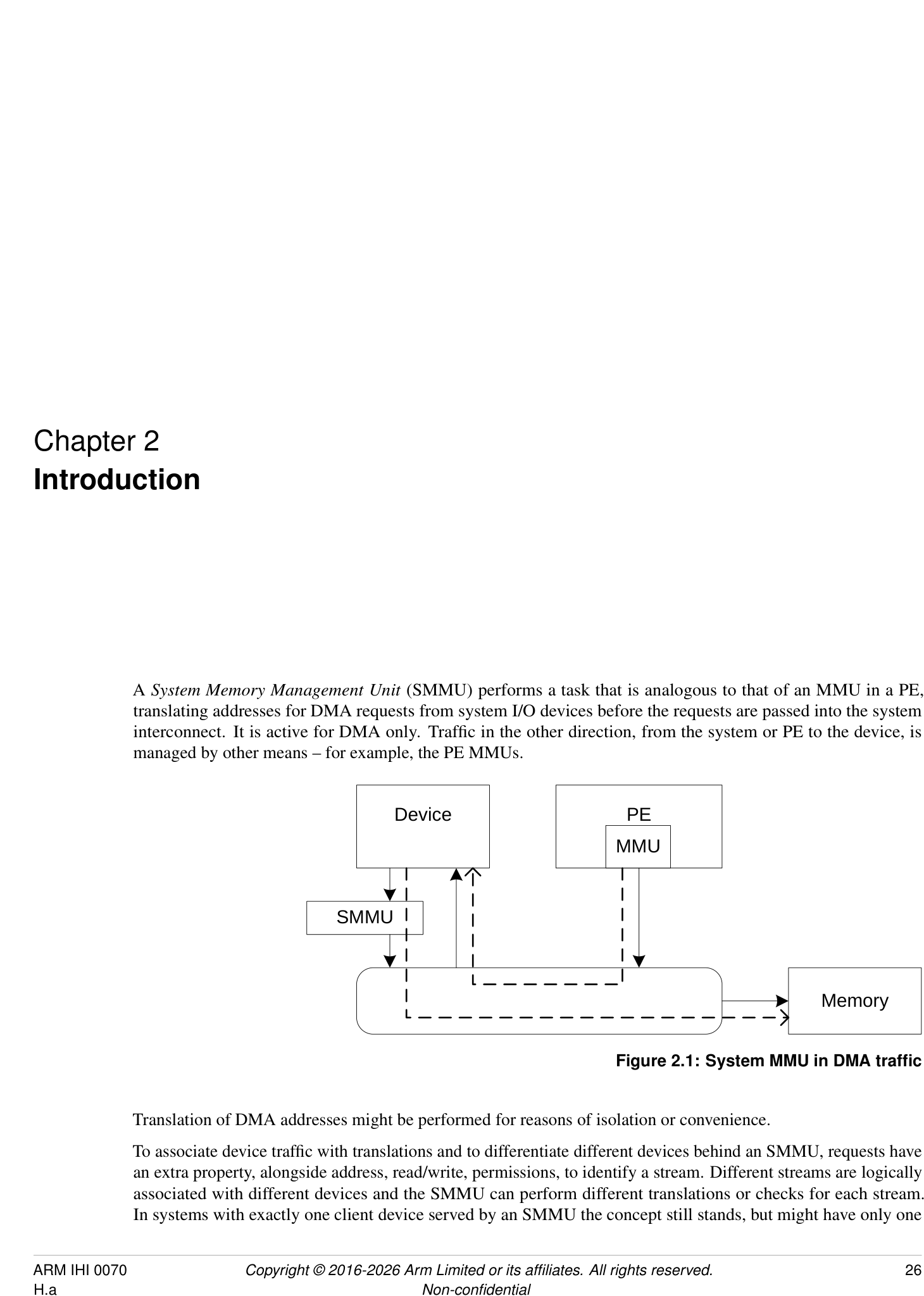
Translation of DMA addresses might be performed for reasons of isolation or convenience.
To associate device traffic with translations and to differentiate different devices behind an SMMU, requests have an extra property, alongside address, read/write, permissions, to identify a stream. Different streams are logically associated with different devices and the SMMU can perform different translations or checks for each stream. In systems with exactly one client device served by an SMMU the concept still stands, but might have only one
stream.
Several SMMUs might exist within a system. An SMMU might translate traffic from just one device or a set of devices.
The SMMU supports two stages of translation in a similar way to PEs supporting the Virtualization Extensions [2]. Each stage of translation can be independently enabled. An incoming address is logically translated from VA to IPA in stage 1, then the IPA is input to stage 2 which translates the IPA to the output PA. Stage 1 is intended to be used by a software entity to provide isolation or translation to buffers within the entity, for example DMA isolation within an OS. Stage 2 is intended to be available in systems supporting the Virtualization Extensions and is intended to virtualize device DMA to guest VM address spaces. When both stage 1 and stage 2 are enabled, the translation configuration is called nested .
2.1 History
-
SMMUv1 supports a modest number of contexts/streams configured using registers, limiting scalability.
-
SMMUv2 extends SMMUv1 with Armv8-A translation table formats, large addresses, with the same limited number of contexts and streams.
SMMUv1 and SMMUv2 map an incoming data stream onto one of many register-based context banks which indicate translation tables and translation configuration to use. The context bank might also indicate a second context bank for nested translation of a second stage (stage 1 and stage 2). The stream is identified using an externally-generated ID supplied with each transaction. A second ID might be supplied to determine the Security state of a stream or group of streams. The use of register-based configuration limits the number of context banks and support of thousands of concurrent contexts is not possible.
Because live data streams might potentially present transactions at any time, the available number of contexts limits the number of streams that might be concurrently enabled. For example, a system might have 1000 network interfaces that might all be idle but whose DMA might be triggered by incoming traffic at any time. The streams must be constantly available to function correctly. It is usually not possible to time-division multiplex a context between many devices requiring service.
The SMMU programming interface register SMMU_AIDR indicates which SMMU architecture version the SMMU implements, as follows:
-
If SMMU_AIDR[7:0] == 0x00, the SMMU implements SMMUv3.0.
-
If SMMU_AIDR[7:0] == 0x01, the SMMU implements SMMUv3.1.
-
If SMMU_AIDR[7:0] == 0x02, the SMMU implements SMMUv3.2.
-
If SMMU_AIDR[7:0] == 0x03, the SMMU implements SMMUv3.3.
-
If SMMU_AIDR[7:0] == 0x04, the SMMU implements SMMUv3.4.
-
If SMMU_AIDR[7:0] == 0x05, the SMMU implements SMMUv3.5.
Unless specified otherwise, all architecture behaviors apply equally to all minor revisions of SMMUv3.
2.2 SMMUv3.0 features
SMMUv3 provides feature to complement PCI Express [1] Root Complexes and other potentially large I/O systems by supporting large numbers of concurrent translation contexts.
-
Memory-based configuration structures to support large numbers of streams.
-
Implementations might support only stage 1, only stage 2 or both stages of translation. This capability, and other IMPLEMENTATION SPECIFIC options, can be discovered from the register interface.
-
Up to 16-bit ASIDs.
-
Up to 16-bit VMIDs [2].
-
Address translation and protection according to Armv8.1 [2] Virtual Memory System Architecture. SMMU translation tables shareable with PEs, allowing software the choice of sharing an existing table or creating an SMMU-private table.
-
49-bit VA, matching Armv8-A’s 2×48-bit translation table input sizes.
Support for the following is optional in an implementation:
-
Either stage 1 or stage 2.
-
Stage 1 and 2 support for the VMSAv8-32 LPAE and VMSAv8-64 translation table format.
-
Secure stream support.
-
Broadcast TLB invalidation.
-
Hardware Translation Table Update (HTTU) of Access flag and dirty state of a page. An implementation might support update of the Access flag only, update of both the Access flag and the dirty state of the page, or no HTTU.
-
PCIe ATS [1] and PRI, when used with compatible Root Complex.
-
16KB and 64KB page granules. However, the presence of 64KB page granules at both stage 1 and stage 2 is suggested to align with the PE requirements in the Server Base System Architecture.
Because the support of large numbers of streams using in-memory configuration causes the SMMUv3 programming interface to be significantly different from that of SMMUv2 [4], SMMUv3 is not designed to be backward-compatible with SMMUv2.
| SMMU feature name | Description | A-profle feature name |
|---|---|---|
| SMMUv3.0-ASID16 | Support for 16-bit ASIDs, see | |
| SMMU_IDR0.ASID16. | ||
| SMMUv3.0-ATS | Support for PCIe ATS, seeSMMU_IDR0.ATS | |
| and [1]. | ||
| SMMUv3.0-BTM | Support for broadcast of TLB maintenance, see | |
| SMMU_IDR0.BTM. | ||
| SMMUv3.0-HAD | Support for disabling hierarchical attributes in | FEAT_HPDS |
| translation tables, seeSMMU_IDR3.HAD. | ||
| SMMUv3.0-HTTUA | Support for hardware translation table Access and | FEAT_HAFDBS |
| SMMUv3.0-HTTUD | dirty state, seeSMMU_IDR0.HTTU. | |
| SMMUv3.0-Hyp | Hypervisor stage 1 contexts supported, see | FEAT_VHE EL2 |
| SMMU_IDR0.HYP. | ||
| SMMUv3.0-GRAN4K | Support for 4KB translation granule, see | |
| SMMU_IDR5.GRAN4K. | ||
| SMMUv3.0-GRAN16K | Support for 16KB translation granule, see | |
| SMMU_IDR5.GRAN16K. | ||
| SMMUv3.0-GRAN64K | Support for 64KB translation granule, see | |
| SMMU_IDR5.GRAN64K. |
| SMMU feature name | Description | A-profle feature name |
|---|---|---|
| SMMUv3.0-PRI | Support for PCIe Page Request Interface, see | |
| SMMU_IDR0.PRI and [1]. | ||
| SMMUv3.0-S1P | Support for Stage 1 translations, see | |
| SMMU_IDR0.S1P. | ||
| SMMUv3.0-S2P | Support for Stage 2 translations, see | |
| SMMU_IDR0.S2P. | ||
| SMMUv3.0-SECURE_IMPL | Support for Secure and Non-secure streams, see | |
| SMMU_S_IDR1.SECURE_IMPL. | ||
| SMMUv3.0-TTFAA32 | Support for VMSAv8-32 LPAE format translation | |
| tables. | ||
| SMMUv3.0-TTFAA64 | Support for VMSAv8-64 format translation tables. | |
| SMMUv3.0-VMID16 | Support for 16-bit VMID, see | FEAT_VMID16 |
| SMMU_IDR0.VMID16. | ||
| SMMUv3.0-ATOS | Support for address translation operation registers, | |
| seeSMMU_IDR0.ATOS. | ||
| SMMUv3.0-VATOS | Support for stage 1-only address translation | |
| operation registers, seeSMMU_IDR0.VATOS. |
SMMUv3.0 also includes a Performance Monitor Counter Group extension, with the following optional features:
| SMMU PMCG feature name | Description |
|---|---|
| SMMU_PMCGv3.0-SID_FILTER_TYPE_ALL | Support for fltering of event counts on a global or per-event basis. See |
| SMMU_PMCG_CFGR.SID_FILTER_TYPE. | |
| SMMU_PMCGv3.0-CAPTURE | Support for software-initiated capture of counter values. See |
| SMMU_PMCG_CFGR.CAPTURE. | |
| SMMU_PMCGv3.0-MSI | Support for PMCG-originated MSIs. SeeSMMU_PMCG_CFGR.MSI. |
| SMMU_PMCGv3.0-RELOC_CTRS | Support for exposing PMCG event counts in independent page of address |
| space. SeeSMMU_PMCG_CFGR.RELOC_CTRS. | |
| SMMU_PMCGv3.0-SECURE_IMPL | Support for counting events from more than one Security state. See |
| SMMU_PMCG_SCRbit [31]. |
2.3 SMMUv3.1 features
SMMUv3.1 extends the base SMMUv3.0 architecture with the following features:
-
Support for PEs implementing Armv8.2-A:
-
Support for 52-bit VA, IPA, and PA.
- [Note:][An][SMMUv3.1][implementation][is][not][required][to][support][52-bit][addressing,][but][the] SMMUv3.1 architecture extends fields to allow an implementation the option of doing so.
-
Page-Based Hardware Attributes (PBHA).
-
EL0 vs EL1 execute-never controls in stage 2 translation tables.
-
Note: Armv8.2 introduces a Common not Private (CnP) concept to the PE which does not apply to the SMMU architecture, because all SMMU translations are treated as common.
-
-
Support for transactions that perform cache-stash or destructive read side effects.
-
Performance Monitor Counter Group (PMCG) error status.
| SMMU feature name | Description | A-profle feature name |
|---|---|---|
| SMMUv3.1-XNX | Provides support for translation table stage 2 | FEAT_XNX |
| Unprivileged Execute-never, see | ||
| SMMU_IDR3.XNX. | ||
| SMMUv3.1-TTPBHA | Provides support for translation table page-based | FEAT_HPDS2 |
| hardware attributes, seeSMMU_IDR3.PBHA. | ||
| SMMUv3.1-VAX | Support for large Virtual Address space, see | FEAT_LVA |
| SMMU_IDR5.VAX. | ||
| SMMUv3.1-LPA | Support for large Physical Address space, see | FEAT_LPA |
| SMMU_IDR5.OAS. |
2.4 SMMUv3.2 features
SMMUv3.2 extends the SMMUv3.1 architecture with the following features:
• Support for PEs implementing Armv8.4-A [2]: – Support for Memory System Resource Partitioning and Monitoring (MPAM) [3]. *[Note:][Support for MPAM is optional in SMMUv3.2.] – Secure EL2 and Secure stage 2 translation. *[All previous rules about Secure streams being stage 1 only are removed.] – Stage 2 control of memory types and cacheability. – Small translation tables support. – Range-based TLB invalidation and Level Hint. – Translation table updates without break-before-make. • Introduction of a Virtual Machine Structure for describing some per-VM configuration.
| SMMU feature name | Description | A-profle feature name |
|---|---|---|
| SMMUv3.2-BBML1 | Support for change in size of translation table | FEAT_BBML1, FEAT_BBML2 |
| SMMUv3.2-BBML2 | mappings, seeSMMU_IDR3.BBML. | |
| SMMUv3.2-RIL | Support for range-based TLB invalidation and | FEAT_TTL, FEAT_TLBIRANGE |
| level hint, seeSMMU_IDR3.RIL. | ||
| SMMUv3.2-SecEL2 | Support for Secure EL2 and Secure stage 2 | FEAT_SEL2 |
| translations, seeSMMU_S_IDR1.SEL2. | ||
| SMMUv3.2-STT | Support for small translation tables, see | FEAT_TTST |
| SMMU_IDR3.STT. | ||
| SMMUv3.2-MPAM | Support for Memory System Resource | FEAT_MPAM |
| Partitioning and Monitoring, see | ||
| SMMU_IDR3.MPAM. | ||
| SMMUv3.2-S2FWB | Support for stage 2 forced Write-Back, see | FEAT_S2FWB |
| SMMU_IDR3.FWB. |
SMMUv3.2 also introduces the following optional features to the PMCG extension:
| SMMU PMCG feature name | Description |
|---|---|
| SMMU_PMCGv3.2-MPAM | Support for associating PMCG-originated MSIs with specifc MPAM |
| PARTID and PMG values. SeeSMMU_PMCG_CFGR.MPAM. |
2.5 SMMUv3.3 features
SMMUv3.3 extends the SMMUv3.2 architecture with the following features:
-
Support for features of PEs implementing Armv8.5 [2]:
-
E0PD feature, equivalent to FEAT_E0PD introduced in Armv8.5.
-
Protected Table Walk (PTW) behavior alignment with Armv8.
-
MPAM_NS mechanism, for alignment with FORCE_NS feature [3].
-
Requirements for interaction with the Memory Tagging Extension [2].
-
-
Enhanced Command queue interface for reducing contention when submitting Commands to the SMMU.
-
• Support for recording non-Translation-related events for ATS Translation Requests.
-
Guidelines for RAS error recording.
| SMMU feature name | Description | A-profle feature name |
|---|---|---|
| SMMUv3.3-E0PD Mandatory | Support for preventing EL0 access to halves of | FEAT_E0PD |
| address maps. SeeSMMU_IDR3.E0PD. | ||
| SMMUv3.3-PTWNNC | Support for treating table walks to Device | |
| Mandatory | memory as Normal Non- cacheable. See | |
| SMMU_IDR3.PTWNNC. | ||
| SMMUv3.3-MPAM_NS | Support for Secure transactions using Non-secure | |
| Optional | PARTID space. See | |
| SMMU_S_MPAMIDR.HAS_MPAM_NS. | ||
| SMMUv3.3-ECMDQ Optional | Support for Enhanced Command queue interfaces. | |
| SeeSMMU_IDR1.ECMDQ. | ||
| SMMUv3.3-SEC_ECMDQ | Support for Enhanced Command queue interfaces | |
| Optional | for Secure state. SeeSMMU_S_IDR0.ECMDQ. | |
| SMMUv3.3-ATSRECERR | Support for recording events on confguration | |
| Optional | errors for ATS translation requests. See | |
| SMMU_IDR0.ATSRECERR. |
SMMUv3.3 also introduces the following optional features to the PMCG extension:
| SMMU PMCG feature name | Description |
|---|---|
| SMMU_PMCGv3.3-FILTER_MPAM | Support for fltering event counts by MPAM attributes. See |
| SMMU_PMCG_CFGR.FILTER_PARTID_PMG. | |
| SMMU_PMCGv3.3-MPAM_NS | Support for issuing PMCG MSIs for Secure state, associated with a |
| Non-secure MPAM PARTID. See | |
| SMMU_PMCG_S_MPAMIDR.HAS_MPAM_NS. |
2.6 SMMU for RME features
SMMU for RME introduces support for Granule Protection Checks, for interoperability with PEs that implement FEAT_RME [2].
There are two aspects to RME support for SMMU:
-
Whether the SMMU has the Root programming interface and can perform Granule Protection Checks. This is advertised with SMMU_ROOT_IDR0.ROOT_IMPL == 1.
-
Whether the SMMU has RME-related changes exposed to the Secure and Non-secure programming interfaces. This is advertised with SMMU_IDR0.RME_IMPL == 1.
Any SMMU behaviors specified as applying to an SMMU with RME apply to an SMMU implementation with SMMU_ROOT_IDR0.ROOT_IMPL == 1.
An SMMU with RME must have SMMU_ROOT_IDR0.ROOT_IMPL == 1. It is permitted for an SMMU with RME to have SMMU_IDR0.RME_IMPL == 0.
An SMMU with RME also implements SMMUv3.2 or later.
An SMMU with SMMU_IDR0.RME_IMPL == 1 does not support the EL3 StreamWorld. This means that:
-
An STE with STRW configured for EL3 is ILLEGAL and results in C_BAD_STE.
-
The commands CMD_TLBI_EL3_ALL, CMD_TLBI_EL3_VA result in CERROR_ILL.
-
The SMMU is not required to perform any invalidation on receipt of a broadcast TLBI for EL3.
Note: The value of SMMU_IDR0.RME_IMPL does not affect support for other features associated with Secure state.
See also 3.25 Granule Protection Checks .
| SMMU RME feature name | Description | A-profle feature name |
|---|---|---|
| SMMUv3.3-RME_ROOT_IMPL | Support for the Root programming interface. See | FEAT_RME |
| SMMU_ROOT_IDR0.ROOT_IMPL. | ||
| SMMUv3.3-RME_IMPL | Support for visibility of GPC faults to the Non-secure, | FEAT_RME |
| Secure and Realm programming interfaces, if supported. | ||
| SeeSMMU_IDR0.RME_IMPL. | ||
| SMMUv3.3-RME_BGPTM | Support for broadcast TLBI PA operations. See | FEAT_RME |
| SMMU_ROOT_IDR0.BGPTM. | ||
| SMMUv3.3-RME_RGPTM | Support for register TLBI by PA. See | |
| SMMU_ROOT_IDR0.RGPTM. |
An SMMU with RME implements either SMMUv3.3-RME_ROOT_IMPL or SMMUv3.3-RME_IMPL.
2.7 SMMU for RME DA features
SMMU for RME DA introduces features that enable the association between devices and software executing in the Realm Security state. See [2].
Any SMMU behavior specified as applying to an SMMU with RME DA apply to an SMMU implementation with SMMU_ROOT_IDR0.REALM_IMPL == 1. This means that in such implementations, Realm programming interface is supported.
| SMMU RME DA feature | ||
|---|---|---|
| name | Description | A-profle feature name |
| SMMUv3.3-RME_DA | Support for the Realm programming interface. See | FEAT_RME |
| SMMU_ROOT_IDR0.REALM_IMPL. | ||
| SMMUv3.3-MEC_R | Support for the RME Memory Encryption Contexts | FEAT_MEC |
| extension. SeeSMMU_R_IDR3.MEC. | ||
| SMMUv3.3-DPT_R | Support for Device Permission Table in Realm state. See | |
| SMMU_R_IDR3.DPT. | ||
| SMMUv3.3-DPT_NS | Support for Device Permission Table in Non-secure state. | |
| SeeSMMU_IDR3.DPT. |
An SMMU with RME DA implements SMMUv3.3-RME_DA.
2.7.1 Required features
An SMMU with SMMU_ROOT_IDR0.REALM_IMPL == 1 implements all the mandatory features from SMMUv3.3, including the following requirements:
| Register feld | Value | Notes |
|---|---|---|
| SMMU_IDR3.PTWNNC | 1 | Mandatory from SMMUv3.3 onwards. |
| SMMU_IDR3.E0PD | 1 | Mandatory from SMMUv3.3 onwards. |
| SMMU_IDR3.STT | 1 | Mandatory because of Secure EL2 requirement. |
| SMMU_IDR3.FWB | 1 | Mandatory from SMMUv3.2. |
| SMMU_IDR3.XNX | 1 | Mandatory from SMMUv3.1. |
| SMMU_IDR3.HAD | 1 | Mandatory from SMMUv3.1. |
An SMMU with SMMU_ROOT_IDR0.REALM_IMPL == 1 additionally has the following features:
| Register feld | Value | Notes |
|---|---|---|
| SMMU_IDR0.Hyp | 1 | Required for EL2. |
| SMMU_IDR0.S1P | 1 | Required for stage 1 translation. |
| SMMU_IDR0.S2P | 1 | Required for stage 2 translation. |
| SMMU_IDR0.TTF | 0b10 | VMSAv8-64 only. |
| SMMU_R_IDR3.DPT | - | Support for DPT is strongly recommended. |
| Register feld | Value | Notes |
|---|---|---|
| SMMU_IDR0.NS1ATS | - | If ATS is supported and DPT is not supported, then split-stage ATS must be supported. |
| SMMU_IDR0.COHACC | 1 | Required for coherent access to RMM-managed tables. |
| SMMU_IDR0.BTM | - | Support for broadcast TLB maintenance is strongly recommended. |
| SMMU_IDR0.HTTU | - | Support for Hardware update of Access Flag and Dirty state is strongly recommended. |
| SMMU_IDR0.RME_IMPL | 1 | Granule Protection Check faults are visible to Non-secure, Realm and Secure states. |
| SMMU_IDR3.BBML | 0b10 | Level 2 support is required. |
| SMMU_ROOT_IDR0.ROOT_IMPL | 1 | SMMU must be able to perform Granule Protection Checks. |
2.8 SMMUv3.4 features
SMMUv3.4 extends the SMMUv3.3 architecture with the following features:
• Support for features of PEs implementing Armv8.7 [2]: – 52-bit virtual and physical address spaces when using 4KB and 16KB translation granule sizes. – Enhanced PAN mechanism. – Requirements for interoperability with PEs that implement FEAT_XS. See 3.17.8 TLBInXS maintenance operations . • Support for features of PEs implementing Armv8.9 [2]: – Stage 1 and Stage 2 permission indirections. – Stage 2 permission overlays. – Translation hardening. – Attribute Index Enhancement. – 128-bit descriptors and 56-bit address spaces. – Table descriptor Access flag. – Stage 2 MemAttr NoTagAccess encodings. • Support for the PASID TLP prefix for use on ATS Translated transactions. • Deprecation of stashing translation information in ATS address fields. • Deprecation of InD and PnU as output attributes. • Deprecation of the SMMU_PMCG_PMAUTHSTATUS register.
| SMMU feature name | Description | A-profle feature name |
|---|---|---|
| SMMUv3.4-LPA2 Optional | Support for 52-bits of virtual and physical address | FEAT_LPA2 |
| space when using the 4KB and 16KB translation | ||
| granule sizes. SeeSMMU_IDR5.DS. | ||
| SMMUv3.4-PAN3 Optional | Support for the Enhanced PAN mechanism. See | FEAT_PAN3 |
| SMMU_IDR3.EPAN. | ||
| SMMUv3.4-THE Optional | Support for translation hardening extension. See | FEAT_THE |
| SMMU_IDR3.THE. | ||
| SMMUv3.4-S1PIE Optional | Support for stage 1 permission indirections. See | FEAT_S1PIE |
| SMMU_IDR3.S1PI. | ||
| SMMUv3.4-S2PIE Optional | Support for stage 2 permission indirections. See | FEAT_S2PIE |
| SMMU_IDR3.S2PI. | ||
| SMMUv3.4-S2POE Optional | Support for stage 2 permission overlays. See | FEAT_S2POE |
| SMMU_IDR3.S2PO. | ||
| SMMUv3.4-D128 Optional | Support for 128-bit translation table descriptors. See | FEAT_D128, FEAT_LVA3, 56-bit |
| SMMU_IDR5.D128, andSMMU_IDR5.{OAS, | physical addresses | |
| VAX}. | ||
| SMMUv3.4-AIE Optional | Support for stage 1 Attribute Index Enhancement. See | FEAT_AIE |
| SMMU_IDR3.AIE. | ||
| SMMUv3.4-HAFT Optional | Support for Table descriptor Access fags. See | FEAT_HAFT |
| SMMU_IDR0.HTTU. | ||
| SMMUv3.4-MTE_PERM | Support for stage 2 MemAttr NoTagAccess encodings. | FEAT_MTE_PERM |
| Mandatory | SeeSMMU_IDR3.MTEPERM. | |
| SMMUv3.4-PASIDTT | Support for use of the PASID TLP prefx on ATS | |
| Optional | Translated transactions. SeeSMMU_IDR3.PASIDTT. |
2.9 SMMUv3.5 features
SMMUv3.5 extends the SMMUv3.4 architecture with the following features:
-
Support for features of PEs implementing Armv9.5 [2]:
-
Above PPS All Access.
-
– Non-Secure only (NSO) GPI encoding.
-
– Interoperability with PEs with FNGx control fields.
-
– Hardware dirty state tracking structure (HDBSS).
-
– Hardware accelerator for cleaning dirty state (HACDBS).
-
– TLBI VMALL for Dirty state.
-
GPT scaling features.
-
Granular Data Isolation.
-
-
Support for Direct-mode Enhanced Command Queues.
-
• Support for virtual to physical StreamID translation.
-
Support for software control of memory type attribute transformation.
| SMMU feature name | Description | A-profle feature name |
|---|---|---|
| SMMUv3.5-RME_APPSAA | Support for Above PPS All Access. See | FEAT_RME_GPC2 |
| Optional | SMMU_ROOT_IDR0.APPSAA. | |
| SMMUv3.5-RME_NSO | Support for the Non-Secure only (NSO) GPI encoding. | FEAT_RME_GPC2 |
| Optional | SeeSMMU_ROOT_IDR0.NSO. | |
| SMMUv3.5-FNG Mandatory | Support for interoperability with a PE with FNGx | FEAT_ASID2 |
| control felds. SeeSMMU_IDR3.FNG. | ||
| SMMUv3.5-HDBSS | Support for hardware dirty state tracking structure. See | FEAT_HDBSS |
| Optional | SMMU_IDR3.HDBSS. | |
| SMMUv3.5-HACDBS | Support for hardware accelerator for cleaning dirty | FEAT_HACDBS |
| Optional | state. SeeSMMU_IDR3.HACDBS. | |
| SMMUv3.5-TLBIW | Support TLBI VMALL for Dirty state. See | FEAT_TLBIW |
| Optional | SMMU_IDR3.TLBIW. | |
| SMMUv3.5-RME_GPTS | Support for the GPT scaling features. See | FEAT_RME_GPC3 |
| Optional | SMMU_ROOT_IDR0.GPTS. | |
| SMMUv3.5-RME_GDI | Support for Granular Data Isolation. See | FEAT_RME_GDI |
| Optional | SMMU_ROOT_IDR0.GDI. | |
| SMMUv3.5-DCMDQ | Support for Direct Enhanced Command Queues. See | |
| Optional | SMMU_IDR6.DCMDQ. | |
| SMMUv3.5-VSID Optional | Support for virtual to physical StreamID. translation. | |
| SeeSMMU_IDR6.VSID. | ||
| SMMUv3.5-MTCOMB | Support for software control of memory type attribute | |
| Mandatory | transformation. SeeSMMU_IDR3.MTCOMB. |
- 2.10. Permitted implementation of subsets of SMMUv3.x and SMMUv3.(x+1) architectural features
2.10 Permitted implementation of subsets of SMMUv3.x and SMMUv3.(x+1) architectural features
An SMMUv3.x compliant implementation can include any arbitrary subset of the architectural features of SMMUv3.(x+1), subject only to those constraints that require that certain features be implemented together.
An SMMUv3.x compliant implementation cannot include any features of SMMUv3.(x+2) or later. Arm strongly recommends that implementations use the latest version available at design time.
2.11 System placement
PEs
M StreamID StreamID
Incoming
S M S device M I/O S M Device
S traffic  interconnect ‘in’ S S 1
SMMU
M Prog I/F S
S I/O M M Device
‘out’
M Outgoing device traffic  interconnect M S 2
System  StreamID RequesterID
interconnect
Incoming PCIe
M S PCIe M Device 1
traffic ATC
S PCIe Switch
SMMU
Root
Complex
M Prog I/F S PCIe
S Device 2
ATC
M Outgoing PCIe traffic
ATS
M S Memory
Port
Root
Figure 2.2: SMMU placement in an example system
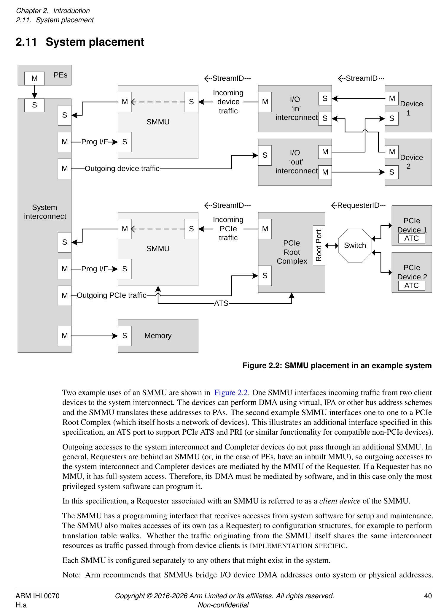
Two example uses of an SMMU are shown in Figure 2.2. One SMMU interfaces incoming traffic from two client devices to the system interconnect. The devices can perform DMA using virtual, IPA or other bus address schemes and the SMMU translates these addresses to PAs. The second example SMMU interfaces one to one to a PCIe Root Complex (which itself hosts a network of devices). This illustrates an additional interface specified in this specification, an ATS port to support PCIe ATS and PRI (or similar functionality for compatible non-PCIe devices).
Outgoing accesses to the system interconnect and Completer devices do not pass through an additional SMMU. In general, Requesters are behind an SMMU (or, in the case of PEs, have an inbuilt MMU), so outgoing accesses to the system interconnect and Completer devices are mediated by the MMU of the Requester. If a Requester has no MMU, it has full-system access. Therefore, its DMA must be mediated by software, and in this case only the most privileged system software can program it.
In this specification, a Requester associated with an SMMU is referred to as a client device of the SMMU.
The SMMU has a programming interface that receives accesses from system software for setup and maintenance. The SMMU also makes accesses of its own (as a Requester) to configuration structures, for example to perform translation table walks. Whether the traffic originating from the SMMU itself shares the same interconnect resources as traffic passed through from device clients is IMPLEMENTATION SPECIFIC.
Each SMMU is configured separately to any others that might exist in the system.
Note: Arm recommends that SMMUs bridge I/O device DMA addresses onto system or physical addresses.
Arm recommends that SMMUs are placed between a device Requester port (or I/O interconnect) and system interconnect. Generally, Arm recommends that SMMUs are not placed in series and that the path of an SMMU to memory or other Completer devices does not pass through another SMMU, whether for fetch of SMMU configuration data or client transactions.
Note: Interconnect-specific channels to support cache coherency are not shown in Figure 2.2.
The SMMU interface to the system interconnect is intended to be IO-coherent, and provide either IO-coherent or fully-coherent access for the client devices of the SMMU.
Note: It is feasible to implement an SMMU as part of a complex device containing fully coherent caches in the same way that the MMU of a PE is paired to fully coherent PE caches. Practically, this means the caches must be tagged with physical addresses.
PCIe  PCIe
Device 0 Device 1
ATC ATC
Switch
Device Device Device
Root
0 1 2
Port
Device Device
0 1 PCIe
Root
I/O interconnect Complex
Complex device  I/O interconnect
with embedded  ‘Smart’
MMU Distributed SMMU C device
ATS
Control &
Embedded Monolithic
translation  TLB TLB
SMMU A SMMU B table walk TLB
System interconnect
Memory
Figure 2.3: Example SMMU implementations
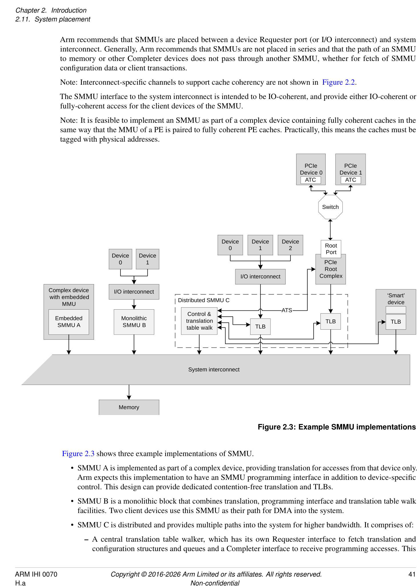
Figure 2.3 shows three example implementations of SMMU.
-
SMMU A is implemented as part of a complex device, providing translation for accesses from that device only. Arm expects this implementation to have an SMMU programming interface in addition to device-specific control. This design can provide dedicated contention-free translation and TLBs.
-
SMMU B is a monolithic block that combines translation, programming interface and translation table walk facilities. Two client devices use this SMMU as their path for DMA into the system.
-
SMMU C is distributed and provides multiple paths into the system for higher bandwidth. It comprises of:
- A central translation table walker, which has its own Requester interface to fetch translation and configuration structures and queues and a Completer interface to receive programming accesses. This
unit might contain a macro-TLB and caches of configuration.
- [The central translation table walker also provides an ATS interface to the Root Complex, so that the] PCIe Devices can use ATS to make translation requests through to the central unit.
-
Remote TLB units which, on a miss, make translation requests to the central unit and cache the results locally. Two units are shown, supporting a set of three devices through one port, and a PCIe Root Complex through another.
-
Finally, a smart device is shown, which embeds a TLB and makes translation requests to the central unit of SMMU C. To software, this looks identical to a simple device connected behind a discrete TLB unit. This design provides a dedicated TLB for the device, but uses the programming interface and translation facilities of the central unit, reducing complexity of the device.
In all cases, it appears to software as though a device is connected behind a logically-separate SMMU (similar to Device 0/1 on SMMU B). All implementations give the illusion of simple read/write transactions arriving from a client device to a discrete SMMU, even if physically it is the device performing the read/write transactions directly into the system, using translations provided by an SMMU.
Note: This allows a single SMMU driver to be used for radically different SMMU implementations.
Note: Devices might integrate a TLB, or whole SMMU, for performance reasons, but a closely-coupled TLB might also be used to provide physical addresses suitable for fully coherent device caches.
Regardless of the implementation style, this specification uses the abstraction of client device transactions arriving at an SMMU. The boundary of SMMU might contain a single module or several distributed subcomponents but these must all behave consistently.